Replacement part HONDA CIVIC 1997 6.G Workshop Manual
[x] Cancel search | Manufacturer: HONDA, Model Year: 1997, Model line: CIVIC, Model: HONDA CIVIC 1997 6.GPages: 2189, PDF Size: 69.39 MB
Page 137 of 2189
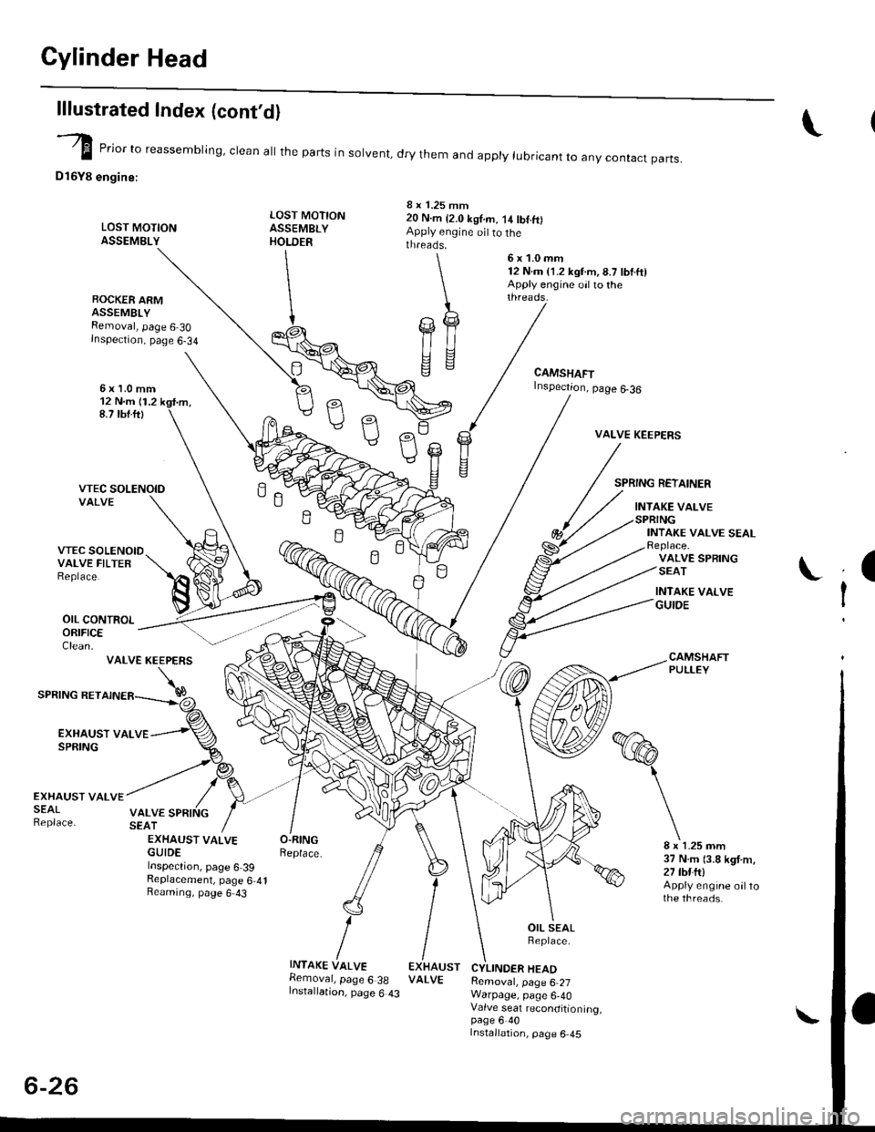
Cylinder Head
lllustrated Index (cont'dl
VALVE KEEPERS
SPRING RETAINER
INTAKE VALVE
VTEC SOLENOIDVALVE FILTEBReplace.
OIL CONTROLORIFICEClean.
INTAKE VALVE SEALReplace.VALVE SPRINGSEAT
INTAKE VAI.VEGUIOE
CAMSHAFTPULLEY
I
I
VALVE KEEPERS
SPRING RET
EXHAUST VALVESPRING
@
EXHAUST VALVESEALReplace.
8 x 1.25 mm37 N.m 13.8 kgt m,27 tbfitlApply engine oiltothe threads.
EXHAUSTVALVE
-vp
e,.io"o reassembring, crean at the parts in sorvent, dry them and appry rubricant to any contact parts.
D16Y8 engine:
LOST MOTIONASSEMgLY
ROCKER ARMASSEMBLYRemoval, page 6 30Inspection, page 6-34
5xl.0mm12 N.m {1.28.7 tbf.ft)
VALVE SPRINGSEATEXHAUSTVALVE O.RINGGUIDE Replace.Inspection, page 6 39Replacement, page 6 41Reaming, page 6 43
LOST MOTIONASSEMBLYHOLDER
INTAKE VALVEBemoval, page 6 38Installation, page 6 43
20 N.m 12.0 kgl.m, 14 tbf.ft)Apply engine oit to thethreads.
\
\
s9illl
CAMSHAFTInspection, page 6-36
OIL SEALBeplace.
CYLINDER HEADRemoval, page 6 27Warpage, page 6-40Valve seat reconditioning,page 6 40Installation, page 6-45
6x1.0mm12 N.m (1.2 kgt.m,8.7 lbf.ftlApply engine oil to thethreads,
Page 203 of 2189
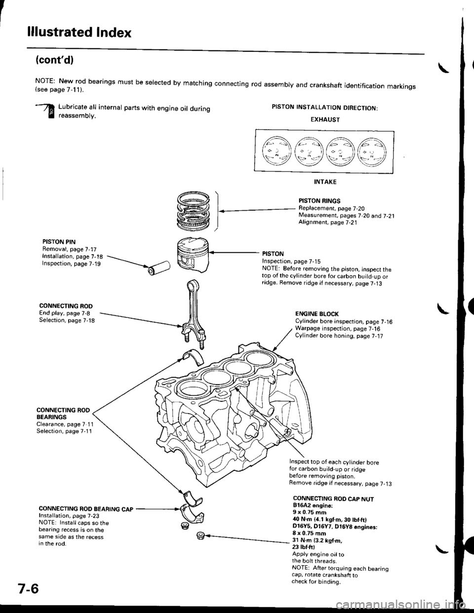
lllustrated Index
(cont'd)
NOTE: New rod bearings must be selected by matching connecting rod assembly and crankshaft(see page 7,11).identification markings
Lubricate all internal parts with engine oil duringreassembtv.
PISTON INSTALLATION DIRECTION:
EXHAUST
4\/=\6\z\
\e/!rqrf/
INTAKE
PISTON RINGSReplacement. page 7-20Measurement, pages 7 20 andj-21Alignment, page 7-21
PISTON PINRemoval, page 7,17Installation, page 7-18Inspection, page 7,19
CONNECTING RODEnd play, page 7-8Selection, page 7,18
CONNECTING RODBEARINGSClearance, page 7 11Selection, page 7-11
CONNECTING ROD BEARING CAPInstallation, page 7-23NOTE: lnstall caps so thebearing recess is on thesame side as the recessin the rod.
PISTONInspectron, page 7-15NOTE: Betore removing the piston, inspect thetop of the cylinder bore for carbon build-up orridge. Bemove ridge if necessary, page 7-13
ENGINE BLOCKCylinder bore inspection, page 7-16Warpage inspection, page 7,'16Cylinder bore honing, page 7,17
Inspect top of each cylinder borefor carbon build-up or ridgebefore removing piston.Remove ridge if necessary, page 7-13
CONNECTING ROD CAP NUT816A2 €ngin6:9 x 0.75 mm{0 N.m (4.1 kgt m, 30 tbf.ftlD16Y5, Dl6Y7. D16Y8 engines:8 x 0.75 mm3l N.m {3.2 kg{.m,23 tbt.fr)Apply engine oiltothe bolt threads.NOTE: After torquing each bearingcap, rotate crankshaft tocheck for binding.
7-6
Page 231 of 2189
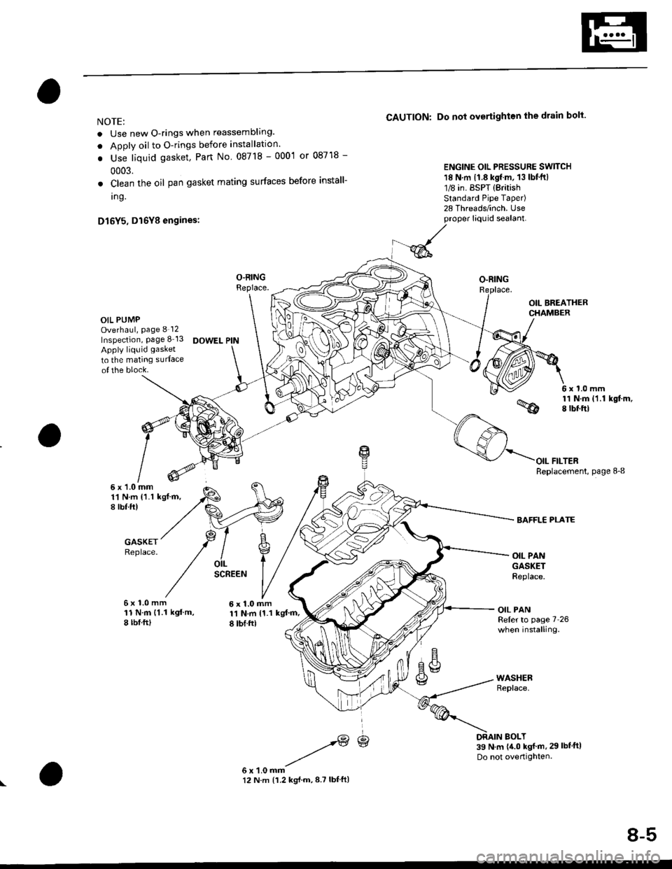
NOTE:
. Use new O-rings when reassembling.
. Apply oil to O-rings before installation.
. Use liquid gasket, Part No 08718 - 0001 or 08718 -
0003.
. Clean the oil pan gasket mating surfaces before install-
Ing.
D16Y5, D16Y8 engines:
O.RINGReplace.
OIL PUMPOverhaul, Page 8 12
Inspection, Page 8 13 OOWEL PINApply liquid gasket
to the mating surface
of the block.
CAUTION: Do not overtightsn the drain bolt.
ENGINE OIL PRESSURE SWITCH18 N,m l'1.8 kgf.m, 13 lbf.ftl
1/8 in. ESPT (British
Standard Pipe Taper)28 Threads/inch. useproper liquid sealant.
O-RING
OIL BREATHERCHAMBER
6x1.0mm11 N.m {1.1 kgf.m,I tbt'ftl
6 x'1.0 mm11 N.m ('1.1 |8 tbf.ft)
GASKETReplace.
FILTERReplacement, page 8_8
BAFFL€ PLATE
6x1.0mm11N.m 11.1 kgl.m,8 tbf.ftl
6x1.0mm11 N.m 11.1 kg{'m,
8 rbf.ftl
OIL PANGASKETFeplace.
OIL PANReler to page 7 26when installing.
\3
6x1.0mm12 N.m {1.2 kg{.m,8.7 lbf ftl
BOLT39 N.m (4.0 kgf.m.29lbtftlDo not overtighten.
\
8-5
Page 261 of 2189
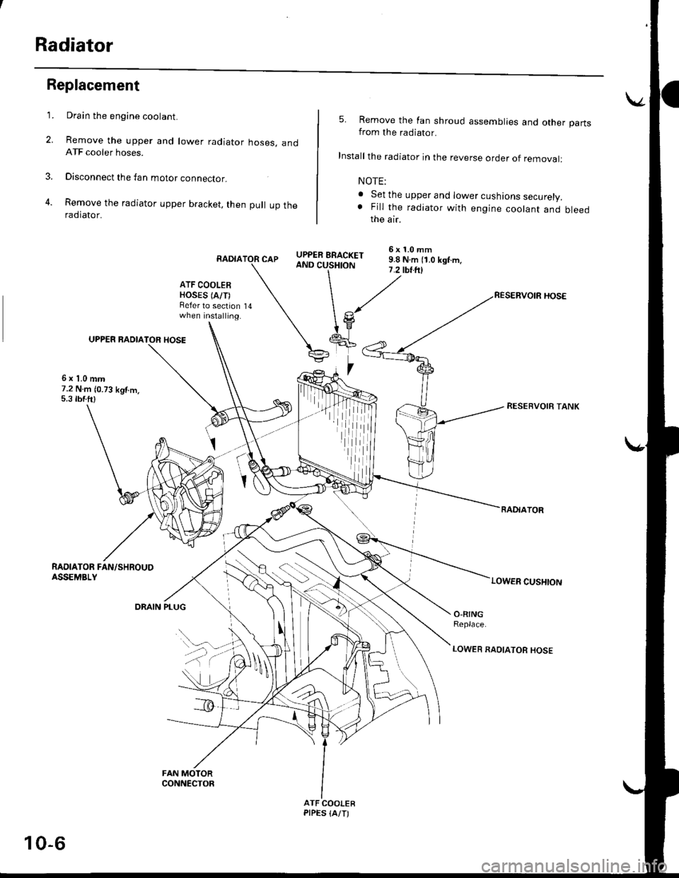
Radiator
Replacement
Drain the engine coolant.
Remove the upper and lower radiator hoses, andATF cooler hoses.
Disconnect the fan motor connector.
Remove the radiator upper bracket, then pull up theraotator,
RADIA
ATF COOLERHOSES (A/T)Refer to sectionwhen installing.
UPPER RAOIATOR HOSE
6x1.0mm7.2 N.m (0.73 kgf.m.5.3 tbf.ft)
1.
2.
3.
5. Remove the fan shroud assemblies and other partsfrom the radiator.
Install the radiator in the reverse order of removal:
NOTE:
. Set the upper and lower cushions securely.. Fill the radiator with engine coolant and bleedthe air.
6x1.0mmCAPY|lT,PS:|" i.i ru- ii b rgr.-,AND CUSHION7.2 tbr.ftl
14
(
I
RESEBVOIR TANK
RADIATOR
LOWER CUSHION
RAOIATOR FAN/SHROUDASSEMBLY
DRAIN PLUGO-RINGReplace.
LOWER RAOIATOR HOSE
ATF COOLERPIPES {A/T)
,iiiiii
10-6
Page 570 of 2189
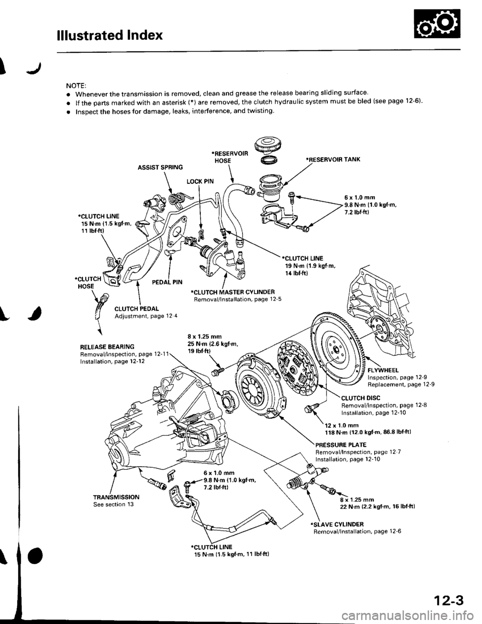
lllustrated Index
\
NOTE:
. Whenever the transmission is removed, clean and grease the release bearing sliding surface
. lf the parts marked with an asterisk (*) are removed, the clutch hydraulic system mustbe bled (seepage 12-6)
. Inspect the hoses for damage, leaks, interference, and twisting
'RESERVOIF TANK
ASSIST SPRING
LOCK PIN
5x1,0mm9.8 N.m (1.0 kgf.m,7.2 tbtftl*CLUTCH LINE15 N.m {1.5 kgJ m,11 tbt.ft)
RELEASE BEARINGRemoval/lnspection, page 12-1 1Installation, page 12-'12
*CLUTCH MASTER CYLINDERRemoval/lnstallation, page 12 5
6x1.0mm9.8 N.m (1.0 kgf.m,7.2 tbf.ft)
FLYWHEELInspectaon, page 12IReplacement, Page 12-9
CLUTCH DISCRemoval/lnspection, page 1 2-8
lnstallation, page 12-'10
'12 x 1.0 mm118 N.m {12.0 kgt'm,86.8lbfft)
PBESSURE PLATEBemoval/lnspection, page 12 7Installation, page 12''10
8 x 1.25 mm22 N m (2.2 kgf.m, 16lbf ft)
ISLAVE CYLINDERRemoval/lnstallation, page 12_6
12-3
Page 607 of 2189
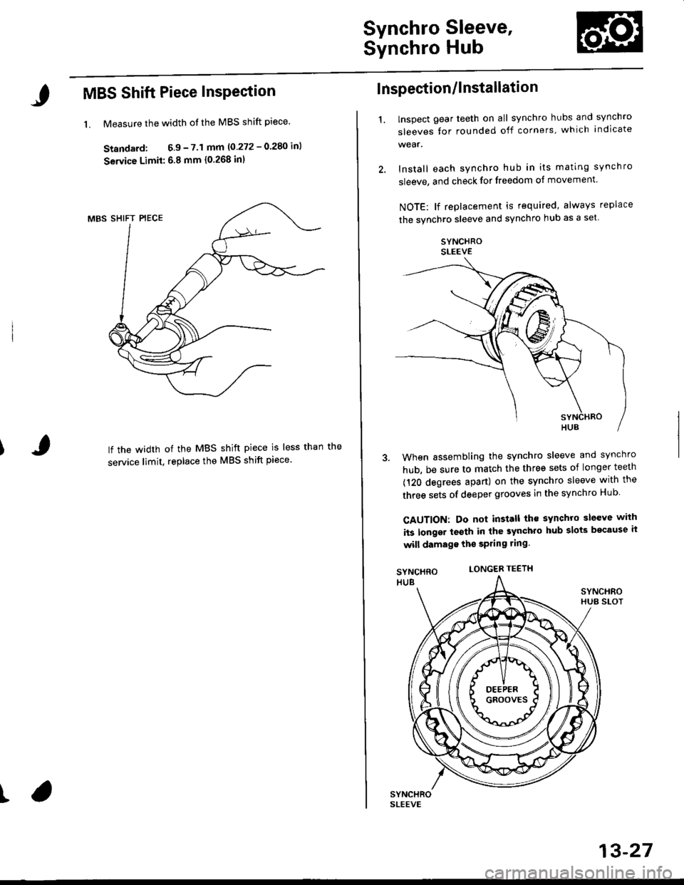
Synchro Sleeve,
Synchro Hub
MBS Shift Piece InsPection
1. Measure the width of the MBS shift piece.
Standard; 6.9 - 7.1 mm 10 272 - 0.280 inl
Service Limit: 6.8 mm {0.268 inl
lf the width of the MBS shift piece is less than
service limit, replace the MBS shift piece'
t
I nspection/l nstallati on
'1.lnspect gear teeth on all synchro hubs and synchro
sleeves tor rounded off corners, which indicate
Install each synchro hub in its mating synchro
sleeve, and check for freedom of movement.
NOTE: lf replacement is required, always replace
the synchro sleeve and synchro hub as a set.
SYNCHROSLEEVE
When assembling the synchro sleeve and synchro
hub, be sure to match the three sets of longer teeth
(120 degrees apart) on the synchro sleeve with the
three sets of deeper grooves in the synchro Hub
CAUTION: Do not install th€ sYnchro sleeve with
its longsr t€sth in the synchro hub slots bocause ii
will damage ths spring ring.
LONGER TEETH
13-27
Page 660 of 2189
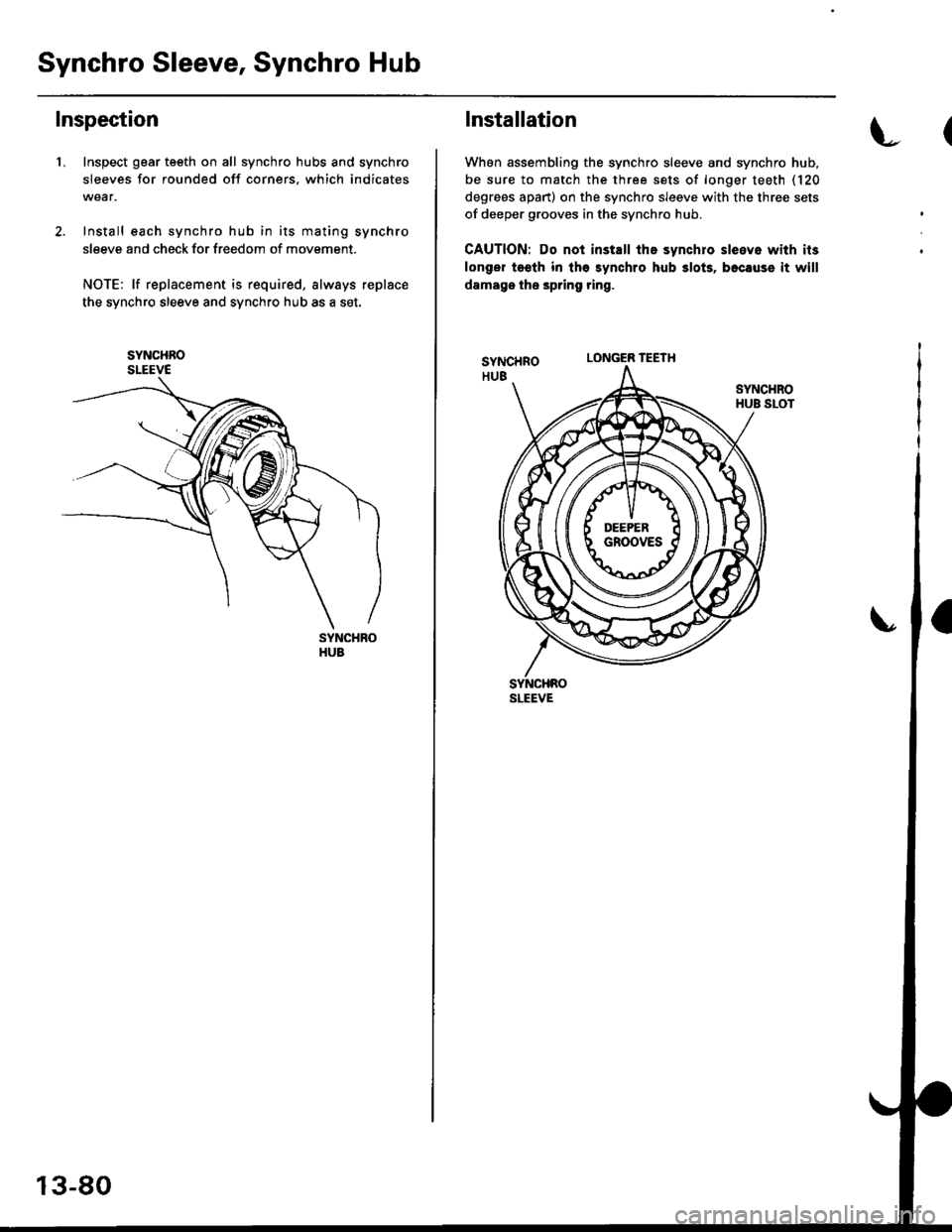
Synchro Sleeve, Synchro Hub
Inspection
1,Inspect gear teeth on all synchro hubs and synchro
sleeves for rounded off corners. which indicates
Install each synchro hub in its mating synchro
sleeve and check for freedom of movement.
NOTE: lf replacement is required, always replace
the synchro sleeve and synchro hub as a set.
Installation
When assembling the synchro sleeve and synchro hub,
be sure to match the three sets of longer teeth (120
degrees apart) on the synchro sleeve with the three sets
of deeper grooves in the synchro hub.
CAUTION: Do noi install tho synchro sleeve with its
longer toeth in the synchro hub slots, because it will
damage the spring ring.
SYNCItROSLEEVCLONGER TEETH
13-80
Page 852 of 2189
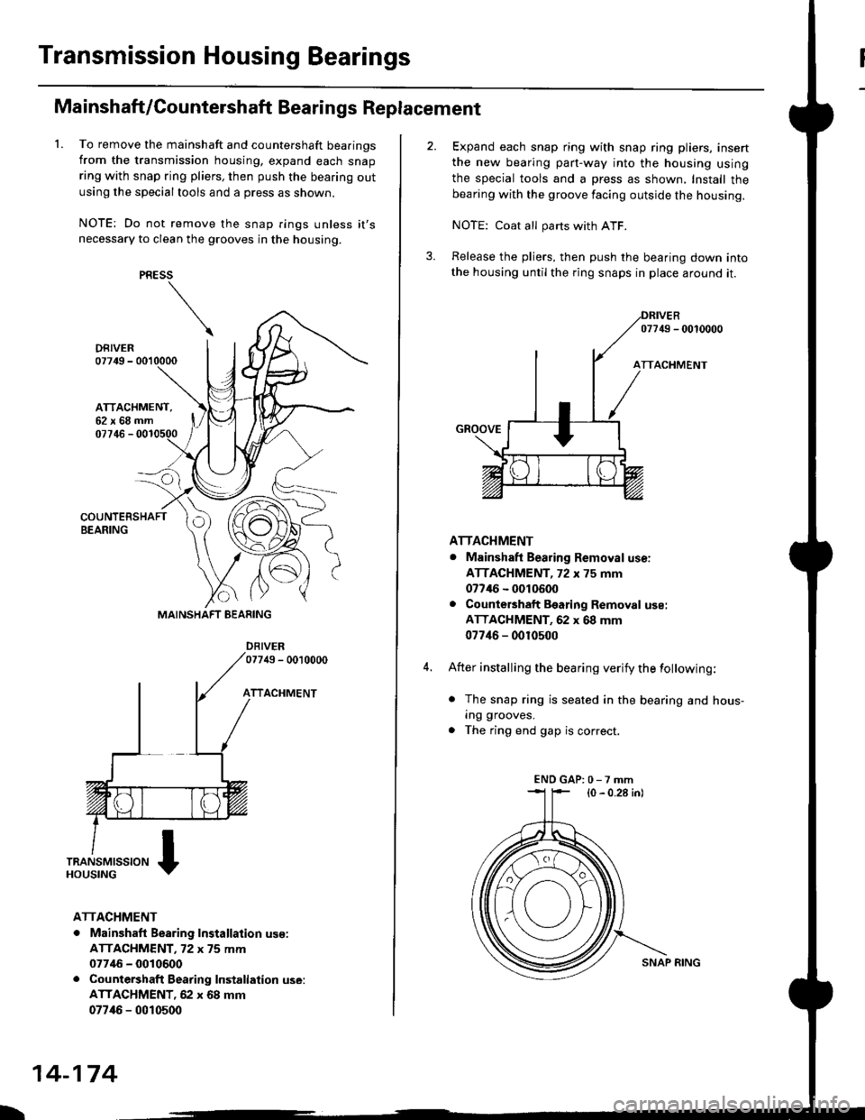
Transmission Housing Bearings
L
Mainshaft/Countershaft Bearings Replacement
To remove the mainshaft and countershaft bearings
from the transmission housing, expand each snap
ring with snap ring pliers, then push the bearing out
using the special tools and a press as shown.
NOTE: Do not remove the snap rings unless it's
necessary to clean the grooves in the housing.
DRIVER07749 - 0010000
ATTACHMENT,62x68mm
PRESS
\
07746 -
DFIVEB07749 - 0010000
TTACHMENT
ATTACHMENT
. Mainshaft Bearing Installation us€:
ATTACHMENT. 72 x 75 mm
07746 - 0010600. Countershaft Bearing Installation use:
ATTACHMENT, 62 x 68 mm
077/16 - 0010500
IRN{L{r.)n
\bZ
MAINSHAFT BEARING
L
14-174
SNAP RING
Expand each snap ring with snap ring pliers, insert
the new bearing part-way into the housing using
the special tools and a press as shown, Install thebearing with the groove facing outside the housing.
NOTE: Coat all parts with ATF.
Release the pliers, then push the bearing down intothe housing until the ring snaps in place around it.
07749 - 0010000
ATTACHMENT
. Mainshaft Bearing Removal use:
ATTACHMENT, 72 x 75 mm
077/16 - 0010600. Counte6haft Bsaring Removal use:
ATTACHMENT, 62 x 68 mm
07746 - 0010500
After installing the bearing verify the following:
. The snap ring is seated in the bearing and hous-
ing grooves.
. The ring end gap is correct.
(0 - 0.28 in)ENDGAP:0-7mm
Page 979 of 2189
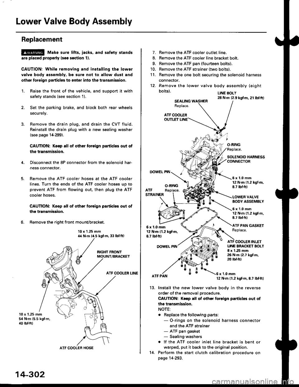
Lower Valve Body Assembly
Replacement
@ Make sure lifts, iacks, and saf€ty stands
are placsd prop€rly {sea section 1).
CAUTION: While removing and installing th6 lower
valve body asssmbly, b€ sule not to allow dust and
other for€ign particles to entsr inio the transmksion.
1. Raise the front of the vehicle, and support it with
safetv stands (see section 1).
2. Set the parking brake, and block both rear wheels
securetv.
4.
6.
Remove the drain plug, and drain the CVT fluid.
Reinstall the drain plug with a new sealing washer(see page 1+299).
CAUTION: Keop all of other toreign parliclos out of
the transmission.
Disconnect the 8P connector from the solenoid har-
ness connector.
Remove the ATF cooler hoses at the ATF cooler
lines. Turn the ends of the ATF cooler hoses up to
prevent ATF from flowing out, then plug the ATF
cooler noses.
CAUTION: Keep all of other foroign particlo3 out of
tho transmission.
Remove the right front mounvbracket.
10 x 1.25 mmila N.m (,1.5 kgf.m, 33 lbtft)
RIGHT FRONTMOUNT/BRACKET
ATF COOLER LINE
10 x 1.25 mmsil N.m 15.5 kgf.m,40 rbr.ft)
ATF COOLER HOSE
14-302
14.
7. Remove the ATF cooler outlet line.
8. Remove the ATF cooler line bracket bolt.
9. Remove the ATF pan (fourteen bolts).
10. Remove the ATF strainer (two bolts).
1 l. Remove the one bolt securing the solenoid harness
connector,
12. Remove the
bolts).
lower valve body assembly (eight
LINE BOLT28 N.m (2.9 kgtm,21 lbtft)SEALINGReplace.
ATF COOI.-EROUTLET
OOWEL PIN
O.RINGFeplace.
SOLENOIO HARNESSCONNECTOR
5x1.0mm12 N.m 11.2 kgt.m,8.7 tbt.ftlO.RINGReplace.ATFSTNAINER
6x1.0mm12 N.m 11.2 kgt m,E.7 tbt'ft)
OOWEL NN
BODY ASSEMBLY
6x1.0mm12 N.m 11.2 kgf.m,8.7 rbf.ft)
ATF PAN GASKETReplace.
VALVE
ATF COOLER INLETUNE BRACKET BOLT8 x 1,25 mm26 N.m {2.7 kgf.m,20 tbf.frl
13.
ATF PANx 1.0 mm12 N.m 11.2 kgf.m, E.7 lbf.ftl
Install the new lower valve bodv in the reverse
ordgr of the removal orocedure.
CAUTION: Koep all ot other fo.oign particles out of
ths transmission.
NOTE:
. Replace the following parts:
- O-rings on the solenoid harness connector
and the ATF strainer- ATF pan gasket- Sealing washers
. lf the ATF cooler inlet line bracket is bent or
warped, put it back to the original position.
Perform the start clutch calibration orocedure on
page 14-293.
Page 1011 of 2189
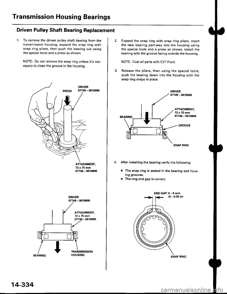
Transmission Housing Bearings
Driven Pulley Shaft Bearing Replacement
1. To remove the driven pulley shaft b'earing trom the
transmission housing, expand the snap ring with
snap ring pliers, then push the bearing out using
the specialtools and a press as shown.
NOTE: Do not remove the snap ring unless it's nec-
essary to clean the groove in the housing.
07749 - 001(xDo
ATTACHMENT,72x75mm07746 - (x'l05U)
077i() - 001(xrco
14-334
SNAP RING
Expand the snap ring with snap ring pliers, insert
the new bearing part-way into the housing using
the special tools and a press as shown. Install the
bearing with the groove facing outside the housing.
NOTE: Coat all pans with CW Fluid.
Release the pliers, then using the special tools,push the bearing down into the housing until the
snap ring snaps in place.
BEARING
ATTACHMENT,72x75mm07746 - OO1 0600
GROOVE
SNAP RING
After installing the bearing verify the following:
o The snap ring is seated in the bearing and hous-
ing grooves.
. The ring end gap is correct.
END GAP| 0 -9 mm
l0 - 0.35 inl