Wire door HONDA CIVIC 1997 6.G User Guide
[x] Cancel search | Manufacturer: HONDA, Model Year: 1997, Model line: CIVIC, Model: HONDA CIVIC 1997 6.GPages: 2189, PDF Size: 69.39 MB
Page 1390 of 2189
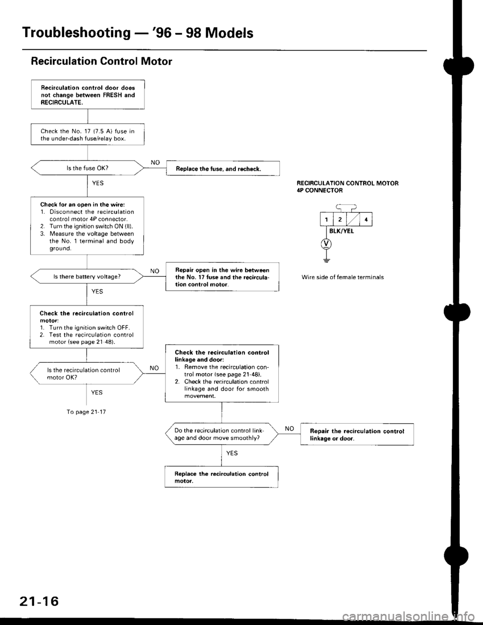
Troubleshooting -'96 - 98 Models
Recirculation Control Motor
Becirculation control door doesnot change between FRESH andRECIBCULATE.
check the No- 17 (7.5 A) fuse inthe under-dash fuse/relay box.
Reolace the tuse. and recheck.
Check for an open in the wire:1. 0isconnect the recirculationcontrol motor 4P connector.2. Tu.n the ignition switch ON (ll).
3. Measure the voltage betweenthe No. l terminal and bodyground.
Repair open in the wir6 betweenthe No. 17Iuse and the recircula-lion conlrol motor.ls there battery voltage?
Check lhe recirculation control
1. Turn the ignition switch OFF.2. Test the recirculation controlmotor {see page 21 48).
Check the recirculation controllinkage and door:1. Remove the recirculation con'trol motor {see page 21 48}.2. Check the recirculation controllinkage and door for smooth
Do the recirculation control linkage and door move smoothly?Reoair the r€circulation controllinkage or door.
RECIRCULATION CONTROL MOTOR4P CONNECTOR
BLK/YEI-
Wire side of temale terminals
Io page 21 17
21-16
Page 1395 of 2189
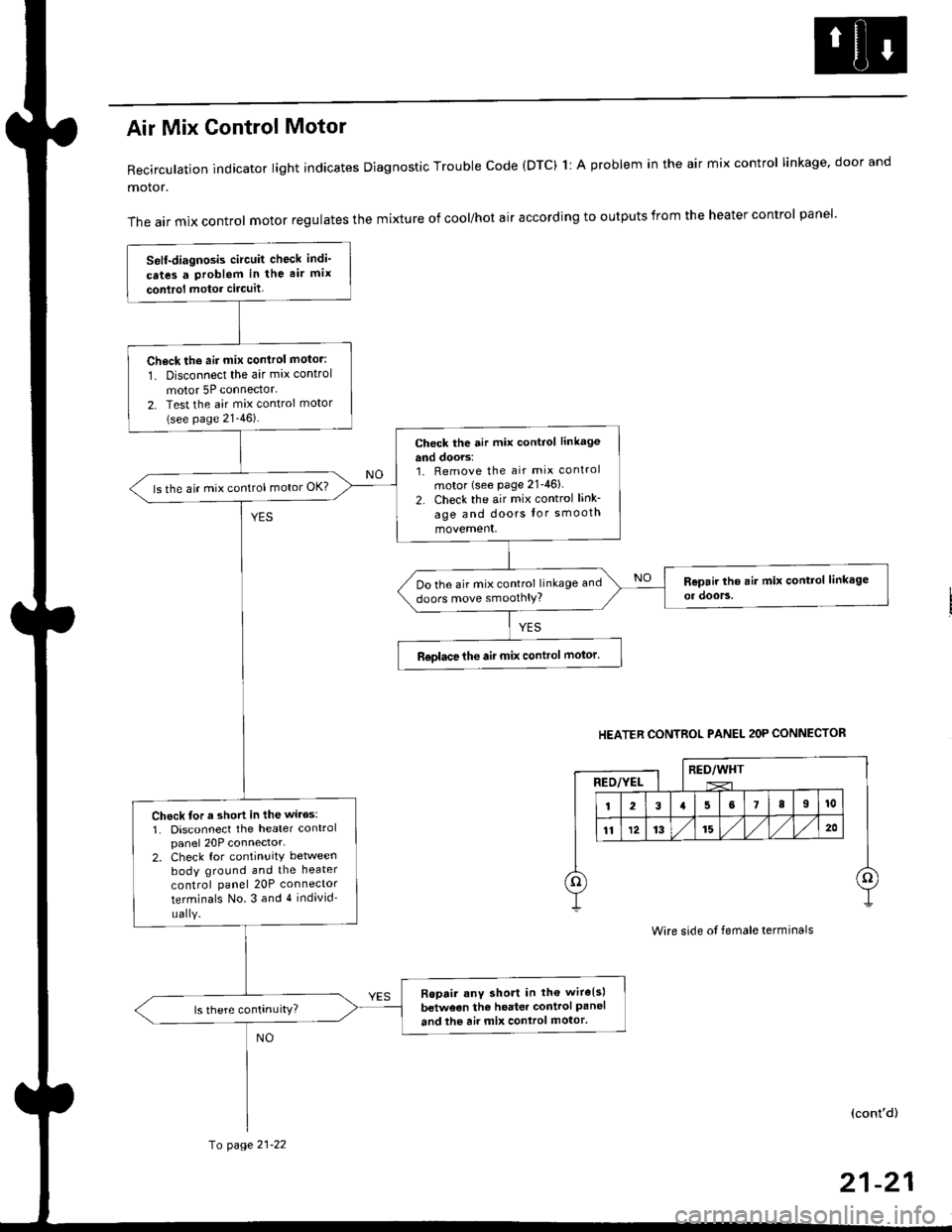
Air Mix Gontrol Motor
Recirculation indicator light indicates Diagnostic Trouble code (DTC) 1l A problem in the air mix control linkage, door and
motor.
The air mix control motor regulates the mixture of cool/hot air according to outputs from the heater control panel'
Self-diagnosis circuit check indi'
cates a Problem in the air mix
conlrol motor circuit,
Check th6 aii mix conirol motor:
1. Disconnect the air mix control
motor 5P connector.
2. Test the air mix control motor(see page 21-46).
check the air mix control linkage
and doors:1. Remove the air mix control
motor (see Page 21-46)
2. Check the air mix control link-
age and doors lor smooth
movement.
ls the air mix control motor OK?
Do the air mix control linkage and
doors move smoolhlY?
R€olace the air mix control motor'
Check tor a short in the wiles:
1. Disconnect the heater controlpanel 20P connector-2. Check for continuitY between
body ground and the heater
control panel 20P connector
terminals No.3 and 4 individ'
uaIY.
Ropair any short in th€ wire{s}
betweon the heater control Paneland the air mix control motor'
HEATER CONTROL PANEL 2OP CONNECTOR
RED/WHTRED/YEL
Wire side ot female terminals
(cont'd)
fo page 21-22
21-21
Page 1397 of 2189
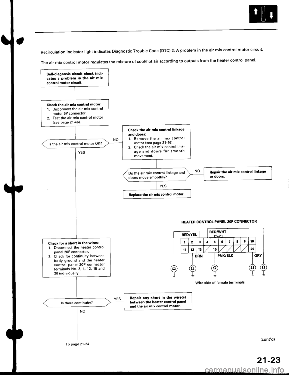
RecirculationindicatorIightindicatesDiagnosticTroublecode(DTc)2:AprobIemintheairmixcontro|motorcircuit.
The air mix control motor regutates the mi)dure of cool/hot air according to outputs from the heater control panel'
Self-diagnosis circuit check indi-
crl6s a problgm in tho air mix
contiol motor circuit.
Check th6 rir mix control motor:
1. Disconnect the air mix control
motor 5P connector'
2. Test the air mix control motor(see page 21-46).
Check the air mix control linkage
and doors:1. Remove the air mix control
motor (see page 21'46).
2. Check the air mix control link-
age and doors for smooth
ls the air mix control motor OK?
Do the air mix control linkage and
doors move smoothlY?
Roglace the air mix conlrol motor.
Check for r short in the wiresl
1. Disconnect the heater controlpanel 20P connector.2. Check for continuity between
body ground and the heater
control panel 20P connector
terminafs No. 3,4. 12,15 a^d
20 individually
Bep.ir any short in the wire{s)
between the h€rter control panel
and th6 air mix control motor.ls there continuity?
HEATER CONTROL PANEL 2OP CONNECTOR
BEO/WHTREO/YEL
PNK/BLK
Wire side of female terminals
(cont'd)
Io page 21-24
21-23
Page 1399 of 2189
![HONDA CIVIC 1997 6.G User Guide Mode control motor does not run.
or one or more modes arc inope]a-
tive.
Check the No. 17 (7.5 A) fuse in
the under-dash fuse/relay box.
Replace the Iuse. and recheck.
Check for an open in the wire:
1](/img/13/6068/w960_6068-1398.png "HONDA CIVIC 1997 6.G User Guide Mode control motor does not run.
or one or more modes arc inope]a-
tive.
Check the No. 17 (7.5 A) fuse in
the under-dash fuse/relay box.
Replace the Iuse. and recheck.
Check for an open in the wire:
1")
Mode control motor does not run.
or one or more modes arc inope]a-
tive.
Check the No. 17 (7.5 A) fuse in
the under-dash fuse/relay box.
Replace the Iuse. and recheck.
Check for an open in the wire:
1. Disconnect the mode control
motor 7P connector,
2. Turn the ignition switch ON (ll)-
3. MeasLrre the voltage between
the No. 1 terminal of themode control motor 7P con
nector and body ground
Repair open in the wire between
the No. 17 luse and lhe mode
control motor.ls there battery voltage?
Check the mode control motor:
1- Turn the ignition switch OFF
2, Test the mode control motor(see page 21 47).Check lhe mode control linkage
and doors:1. Remove the mode controlmotor (see page 21 47).
2. Check the mode control linkage
and doors for smooth move
ls the mode control motor OK?
Do the mode control linkage
and doors move smoothlY?
ReDlace the mode control motor'
Check for a short to Power in the
wires:1. Iurn the,gnitjon switch ON(ll).
2, Disconnect the heater controlpanel20P connector.3. Check for voltage betweenthe No. 2, 5, 6, 7, I and 9 ter'minals of the heater controlpanel 20P connector andbody ground individuallY.Repair shorl to power in the
wire{sl between the heater con-
trol oanel and the mode controlmotor. This short also damagesthe heater control Pan6l. RePair
the short to power before replac'ing the heater control Panel
ls lhere any voltage?
MODE CONTROL MOTOR 7P CONNECTOR
t2315
BLK/YEL
Wire side of female terminals
HEATER CONIROL PANEL 2OP CONNECTOR
Wire side of female terminals
NO
(cont'd)
21-25Io page 21 26
Page 1401 of 2189
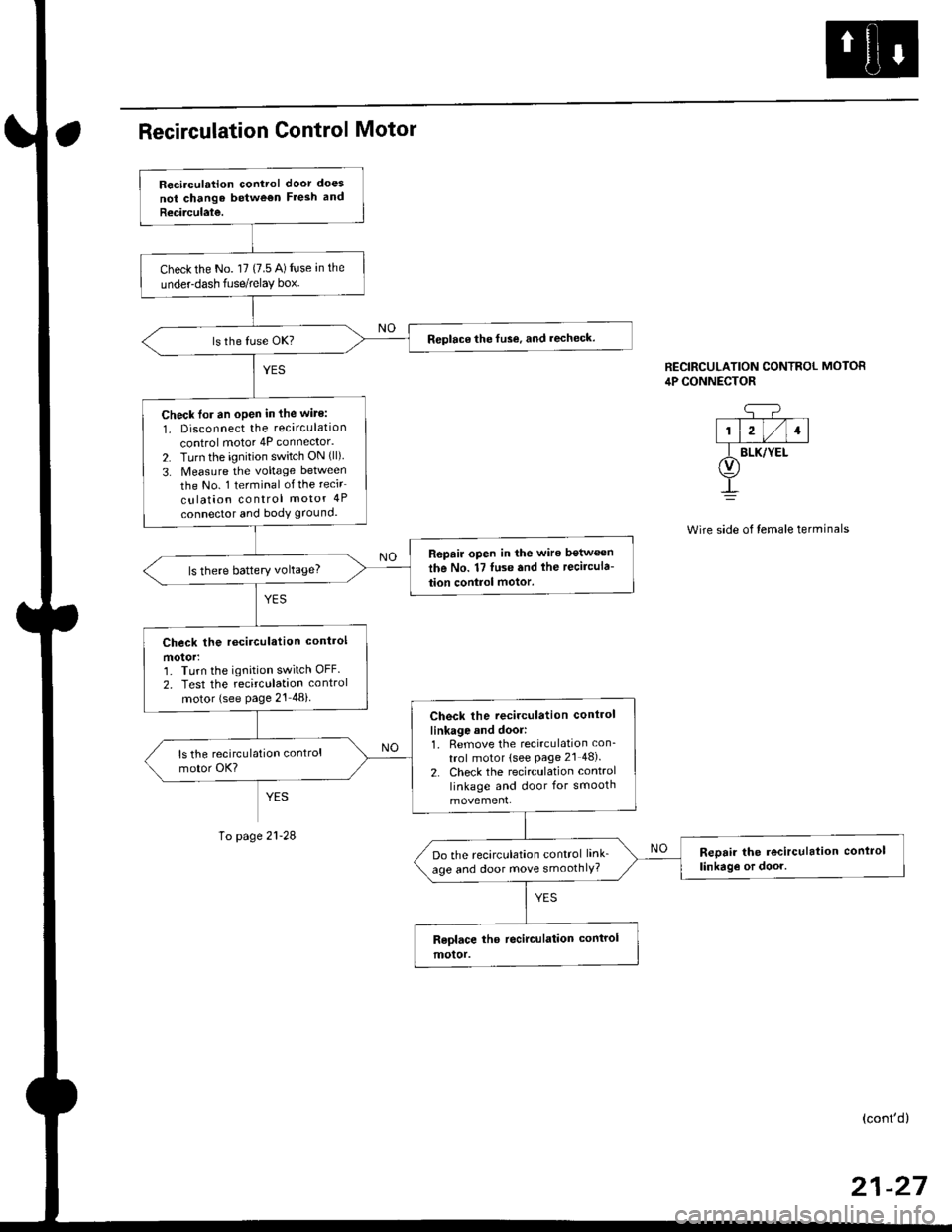
Recirculation control door does
not chango betwe€n Fresh and
Recirculate.
Check the No. l7 (7.5 A) fuse an the
underdash fuse/relay box.
Replace the fuse, and recheck.
Check lor an oPen in the wite:
1. Disconnect the recirculation
control motor 4P connector.
2. Turn the ignition switch ON (ll)
3. Measure the voltage between
the No. 1 terminal of the recir
culation control motor 4P
connector and body ground.
Repair open in the wire between
the No. 17 luse and lhe recircula-
tion control motor.ls there battery voltage?
Check the rccirculation control
motorr'] Turn the ignition switch OFF.
2. Test the recirculation control
motor (see Page 21 48i
Check the recirculation control
linkage and door:1. Remove the recirculation con_
trol motor lsee Page 2l 48).
2. Check the recirculation control
linkage and door for smooth
movement.
Reoair the recirculation conlrol
linkag€ or door.Do the recirculation control link_
age and door move smoothlY?
CONTROL MOTOR
side of temale terminals
RECIRCULATION CONTRC,lP CONNECTOR
q-?--T--T--T-|1l2l/l1l
f BLK/YEt(v)
!
page
(cont'd)
Page 1421 of 2189
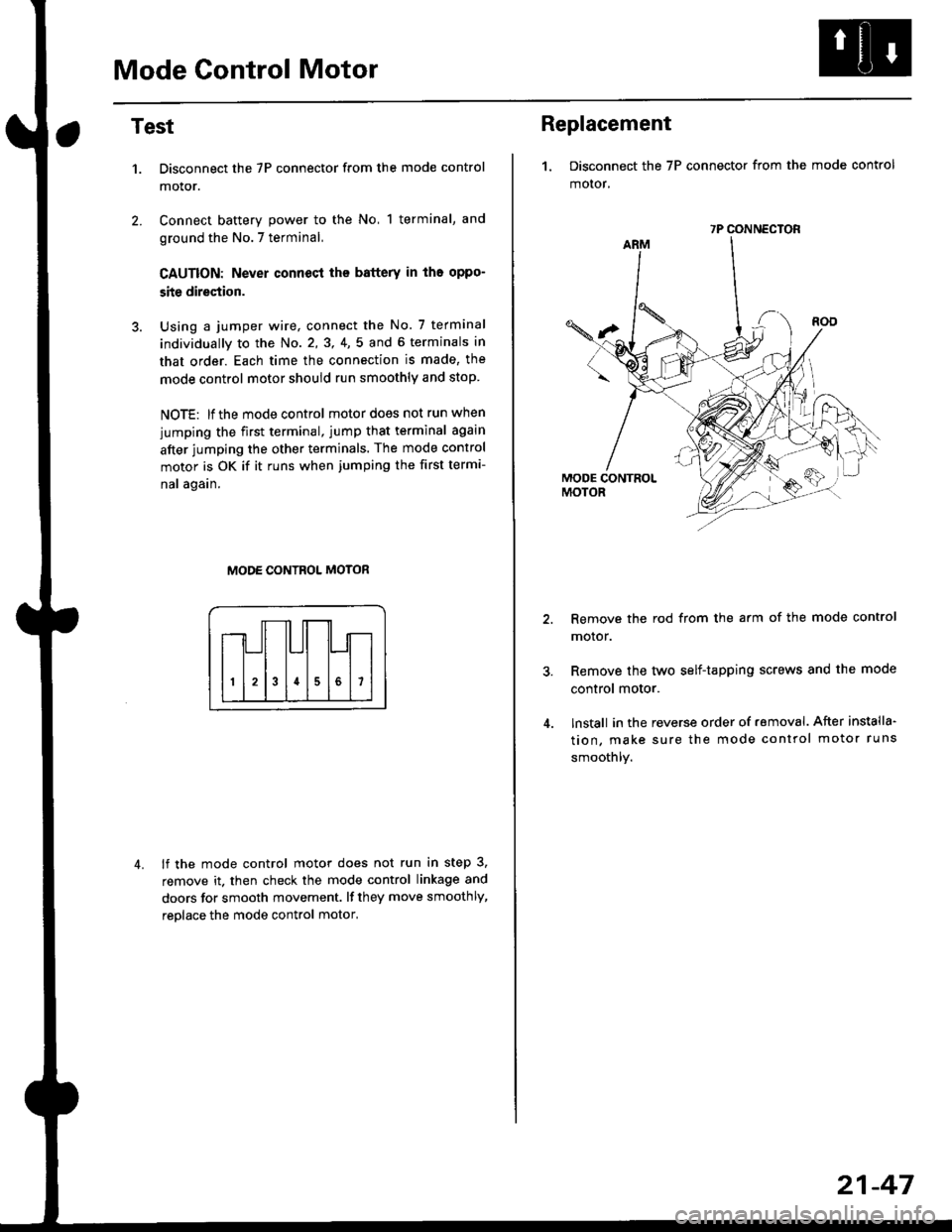
Mode Control Motor
2.
Test
1.
4.
Disconnect the 7P connector from the mode control
motor.
Connect battery power to the No, 1 terminal, and
ground the No.7 terminal,
CAUTION: Never connecl the battery in iho oppo-
site direction.
Using a jumper wire, connect the No. 7 terminal
individually to the No. 2,3, 4,5 and 6 terminals in
that order. Each time the connection is made, the
mode control motor should run smoothly and stop.
NOTE: lf the mode control motor does not run when
jumping the first terminal, jump that terminal again
after jumping the other terminals. The mode control
motor is OK if it runs when jumping the first termi-
nal again.
MODE CONTROL MOTOR
lf the mode control motor does not run in step 3,
remove it. then check the mode control linkage and
doors for smooth movement. lf they move smoothly,
reolace the mode control motor,
Replacement
1. Disconnect the 7P connector from the mode control
motor,
Remove the rod from the arm of the mode control
motor.
Remove the tyvo self-tapping screws and the mode
control motor.
lnstall in the reverse order of removal. After installa'
tion, make sure the mode control motor runs
smoothly.
7P CONNECTOR
21-47
Page 1422 of 2189
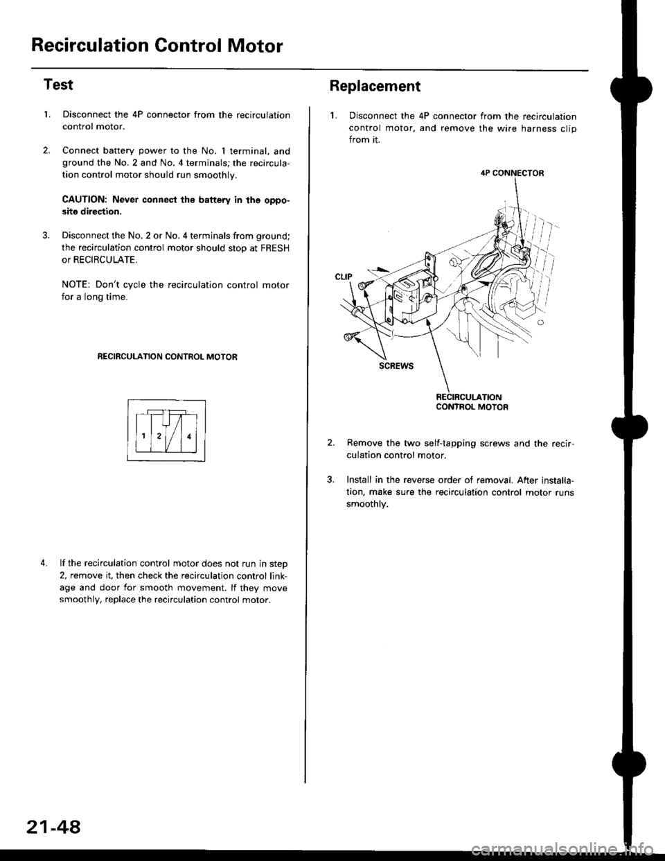
Recirculation Control Motor
Test
LDisconnect the 4P connector from the recirculation
control motor.
Connect battery power to the No. I terminal, andground the No.2 and No. 4 terminals; the recircula-
tion control motor should run smoothly.
CAUTION: Never connest ths battery in the oppo-
site direction.
Disconnect the No. 2 or No. 4 terminals from ground;
the recirculation control motor should stop at FRESH
or RECIRCULATE.
NOTE: Don't cycle the recirculation control motor
for a long time.
RECIRCULATION CONTROL MOTOR
4. lf the recirculation control motor does not run in step
2, remove it, then check the recirculation control link-
age and door for smooth movement. lf they move
smoothly, replace the recirculation control motor.
21-48
Replacement
L Disconnect the 4P connector from the recirculation
control motor, and remove the wire harness clip
from it.
Remove the two self-tapping screws and the recir-
culation control motor.
Install in the reverse order of removal. After installa,
tion, make sure the recirculation control motor runs
smoothly.
4P CONNECTOR
CONTROL MOTOR
Page 1471 of 2189
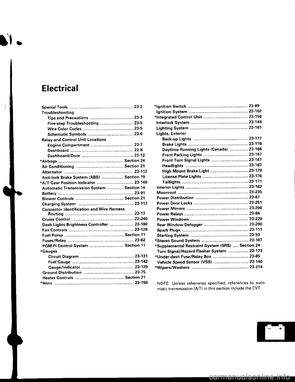
l'f .
Electrical
Special Toofs .,....................,23-2
Troubleshooting
Tips and Precautions ..............,.................... . 23-3
Five-step Troubleshooting .............. ......... . . 23-5
wire color codes ..........,23-5
Schematic Symbols ........,................... . . .. .... 23-6
Relay and Control Unit Locations
Engine Compartment ...,..................... ... .. . 23'7
Dashboard ......................23-8
Dashboard/Door ......... 23-12*Airbags ................. ....... Section 24
Air Conditioning ......... Section 21
Aftelnator ..........."""" """ 23-112
Anti-lock Brake System {ABS) Section 19*A/T Gear Position Indicator .....................,. .... ... 23-149
Automatic Transmission Svstem .... . ....... Section 14
Batterv ......... . . . ... ...... .......23-91
Blower controls .. . ... Section 2l
Charging System ....'...........23'112
Connector ldentilication and Wire Harness
Routing .................. ......23'13
Cruise Control ............,........23-240
Dash Lights Brightness Controller ............. ....... 23-180
Fan controfs "" 23'126
Fuel PumD ........ . ........ section 11
Fuses/Refay ...............,..,,.. 23'62
PGM-FI Control System ......................,....... Section 1 1
*Gauges
Circuit Diagram ....,.,.......23-131
Fuef Gauge ...........'.'.......23-142
Gauge/lndicator .. . .. 23-129
Ground Distribution .. . 23-75
Heatei controls .. . ..... Section 21*Horn................. ...............23-196
*tgnition Switch ....................23-89
lgnition System .......,.... 23-102
*lntegrated Control Unit ....................................... 23-156
fnterlock System ,........ . . , ,23-144
Lighting System . . . .. ......... 23-161
Lights, Exterior
Back-up Lights ..'............23'171
Brake Lights .................. 23'174
Daytime Bunning Lights (Canadal ............... 23'166
Front Parking Lights ......,................ .'. .......... 23-167
Front Turn Signal Lights .......... . . ............ ..,.23-167
Headtights ....".'....-... ..... 23'167
High Mount Brake Light ...................... ... .23'179
License Plate Lights ...... 23'176
Taitfights ................ .......23'171
lnterior Lights ..-.......,, . 23-142
Moonroof ..,.................,........ 23-235
Power Distribution ....... . . .23-61
Power Door Locks .......,,,. .23'251
Power Mirrors ,..............,.,...23'206
Power Relays ....... . ...... . . .. 23-86
Power Windows ............,,....23-220
Rear Window Defogger .......................... . . ... . . 23-2OO
Spark Plugs . ..... . ........ .....23-111
Slarting System ................23-93*stereo Sound Svstem ,................. ..... ... . ... ,.,.,,23'147'Supplemental Restraint System (SRS) ... . Section 24
Turn Signal/Hazard Flasher System .......'.'....-... 23-173
*Undel-dash Fuse/Relay Box ............,.................. 23-85
vehicfe soeed sensor (VSSI """" ""' 23-140+Wipers/Washers .........,.,.,...23-214
NOTE: Unless otherwise specified, references to auto-
matic transmission (Mf) in this section include the CVT.
Page 1483 of 2189
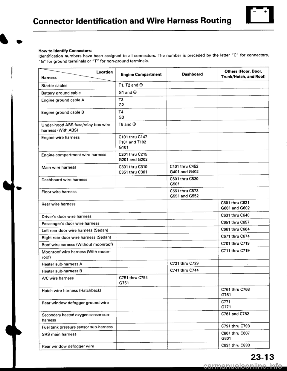
Connector ldentification and Wire Harness Routing
D
How to ldentify Connectors:
ldentification numbers have been assigned to all connectors. The number is preceded by the letter "C" for connectors,"G" for ground terminals or "T" for non-ground terminals.
Location
HarnessEngine CompartmentDashboardOthers {Floor, Door,
Trunk/Hatch, and Rootl
Starter cablesT1, T2 and @
Battery ground cableG1 and O
Engine ground cable AT3
G2
Engine ground cable BT4
Under-hood ABS fuse/relay box wire
harness (With ABS)
t5 ano (9
Engine wire harnessCl01 thru C147
T101 and T102
G101
Engine compartmenl ware harnessC201 thru C215
G201 and G202
Main wire harnessC301 thru C310
C351 thru C361
C401 thru C452
G401 and G402
Dashboard wire harnessC501 thru C520
G501
FIoor wire harnessC551 thru C573
G551 and G552
Rear wire harnessC601 thru C62l
G601 and G602
Driver's door wire harnessC631 thru C640
Passenger's door wire harnessC651 thru C657
Left rear door wire harness (Sedan)C661 thru C664
Right rear door wire harness (Sedan)C671 thru C674
Roof wire harness (Without moonroof)C701 thru C719
Moonroof wire harness {With moon-
roof)
C7l'l thru C719
Heater sub-harness AC721 thru C729
Heater sub-harness BC7 41 thtu C7 44
Ay'C wire harnessC751 thru C754
G751
Hatch wire harness (Hatchback)C761 thru C768
Rear window defogger grgund wirec771
G171
Secondary heated orygen sensor sub-
narness
C781 and C782
Fuel tank pressure sensor sub-harnessC791 thru C793
SRS main harnessC801 thru C807
G801
Rear window defogger wireC831 thru C833
Page 1506 of 2189
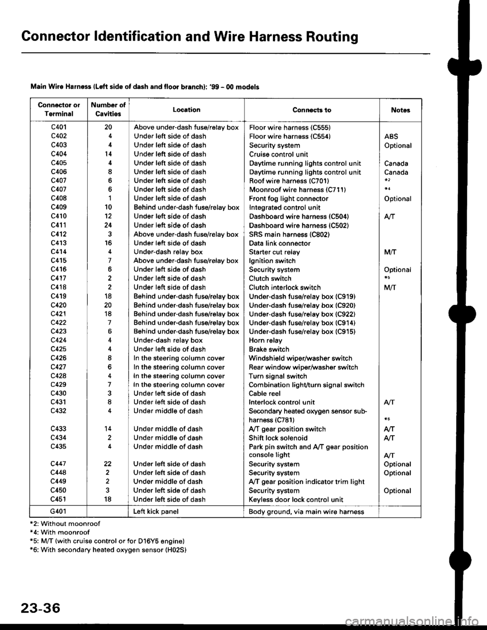
Connector ldentification and Wire Harness Routing
Connosto! ol
Tsrminal
Number of
CavitiesLocationConnoqtg toNotes
c401
c402
c403
c404
c405
c406
c407
c407
c408
c409
c410
c411
c412
c4'I3
c4't4
c415
c416
c417
c418
c419
c420
c42l
c422
c423
c424
c425
c426
c427
c428
c429
c430
c431
c432
c433
c434
c435
c447
c448
c449
c450
c451
20
4
14
I
6
1
10
12
24
16
4
7
6
2
18
20
18
7
4
8
o
7
8
14
22
18
Above under-dash fuse/relay box
Under left side of dash
Under left side of dash
Under left side of dash
Under left side of dash
Under left side of dash
Under left side of dash
Under left side of dash
Under left side of dash
Behind under-dash fuse/relay box
Under left side of dash
Under left side of dash
Above under-dash fuse/relay box
Under left side of dash
Under-dash relay box
Above under-dash fuse/relay box
Under left side of dash
Under left side of dash
Under left side of dash
Behind under-dash fuse/relay box
Behind under-dash fuse/relay box
Behind under-dash fuse/relay box
Behind under-dash fuse/relay box
Behind under-dash fuse/relay box
Under-dash relay box
Under left side of dash
In the steering column cover
In the steering column cover
In the steering column cover
In the steering column cover
Under lett side of dash
Under left side of dash
Under middle of dash
Under middle of dash
Under middle of dash
Under middle of dash
Under left side of dash
Under left side of dash
Under middle of dash
Under left side of dash
Under left side of dash
Floor wire harness (C555)
Floor wire harness (C554)
Security system
Cruise control unit
Daytime running lights control unit
Daytime running lights control unit
Roof wire harness (C701)
Moonroof wire harness {C711)
Front fog light connector
Intagrated control unit
Dashboard wire harness (C504)
Dashboard wire harness (C502)
SRS main ha.ness (C802)
Data link connector
Starter cut relay
lgnition switch
Security system
Clutch switch
Clutch interlock switch
Under-dash fus€/relay box (C919)
Under-dash fuse/relay box (C920)
Under-dash fuse/relay box (C922)
Under-dash fuse/relay box (C914)
Under-dash fuse/relay box (C915)
Horn relay
Brake switch
Windshield wiper/washer switch
Rear window wiper/Washer switch
Turn signal switch
Combination light/turn signal switch
Cable reel
lnterlock control unit
Secondary heaied oxygen sensor sub-
harness (C781)
A/T gear position switch
Shift lock solenoid
Park pin switch and A,/T g€ar position
console light
Security system
Security system
IVT gear position indicator trim light
Security system
Keyless door lock control unit
ABS
Optional
Canada
Canada
Optional
At-|.
M/T
Optional
M/T
Atr
Optional
Optional
Optional
Atr
AIT
AJ-|.
G401Left kick panelBody ground, via main wire harness
Main Wire Halness lLoft side of dash 8nd lloor branchl: '99 - 00 mod€ls
*2: Without moonroof*4: With moonroof*5: M/T (with cruise control or for Dl6Y5 engine)*6: With secondary heated oxygen sensor (H02S)
23-36