Wire door HONDA CIVIC 1997 6.G Owner's Guide
[x] Cancel search | Manufacturer: HONDA, Model Year: 1997, Model line: CIVIC, Model: HONDA CIVIC 1997 6.GPages: 2189, PDF Size: 69.39 MB
Page 1549 of 2189
t
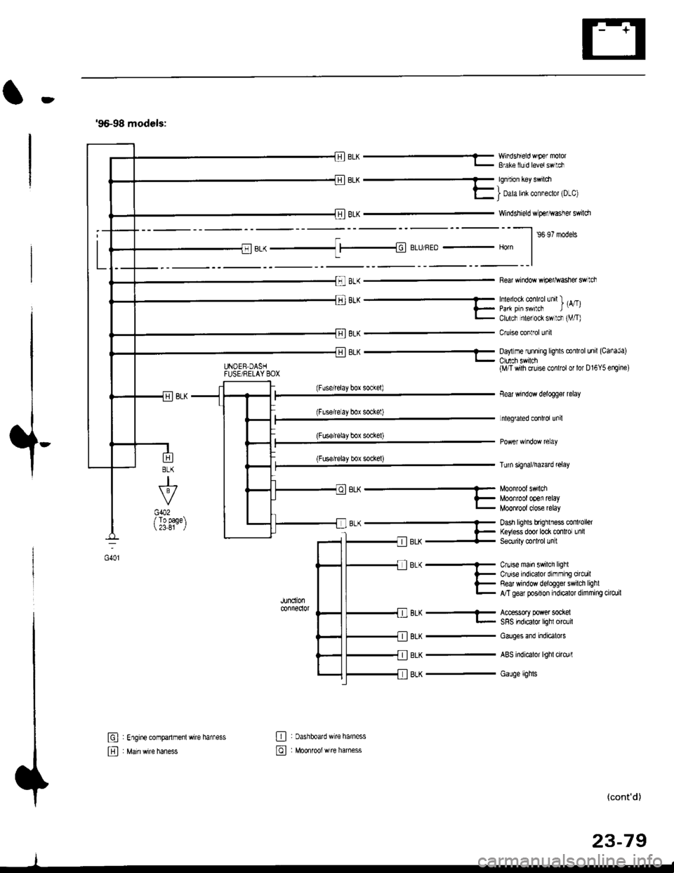
'96-98 models:
BLK -..1 |-|d BLIJ/REo - Horn
8LK
J
G402/ To page 23,81
6L^ --...........-- Munn'un' 5.nLi
?_ Moofrootooen retayL MOOnTOOI dose relay
B-(- Dash hghls bfrqrlless co 'oel
l- ftyess door to* mnlror Lnil-llerX + Seorriry @rl'ol Jn :
JUndonconnedor
BLK
BLK
BLK
Cnrise main swilch lighlCruise indicalor dirnming orcuilRed window deloggel swilch lighlA/T gear posilion indicalor dimming cilo./il
Accessory power sockelSRS indicalor lighl circlil
Cauges end indicatols
ABS indicalor lighl cirq)rl
Gauge lights
El : Engine companmenl wire harness
E , M"in *it" h"n"..
E : oashboatd w€ haness
@ : Moonrool w re harness
UNOEB,DASHFUSE/RELAY BOX
EL^ - YY'iisnEo 'F€ "'v'u'- Bfale llJ d levetswlci
qq.-_
E I Dah Inl col"eclot 'D-cl
Windshield w perhvasher swildr
--l ,o ,? '.da.
Rear window wip€r^vasher swtch
'''"_- -- , rA/Tll_ paa pirswilcF t-,l- Clulcf nlel ock sw lcr rVT)
Cruise conlrol unil
8LK - Da,'lm€ runnrng lrghts conltol unil (CanaJa)
(Fuserelay box sockel)
(Flserelay bor sockel)
(Fuse/relay box socke0
(Fuse/relay box sockel)
BLK-
(M/T wilh cruise conlfol or lor D16Y5 erEine)
Bear window delogger relay
Lnlegrated conlrol unil
Turn signal/hazad @lay
(cont'd)
23-79
oot
Page 1550 of 2189
Ground Distribution
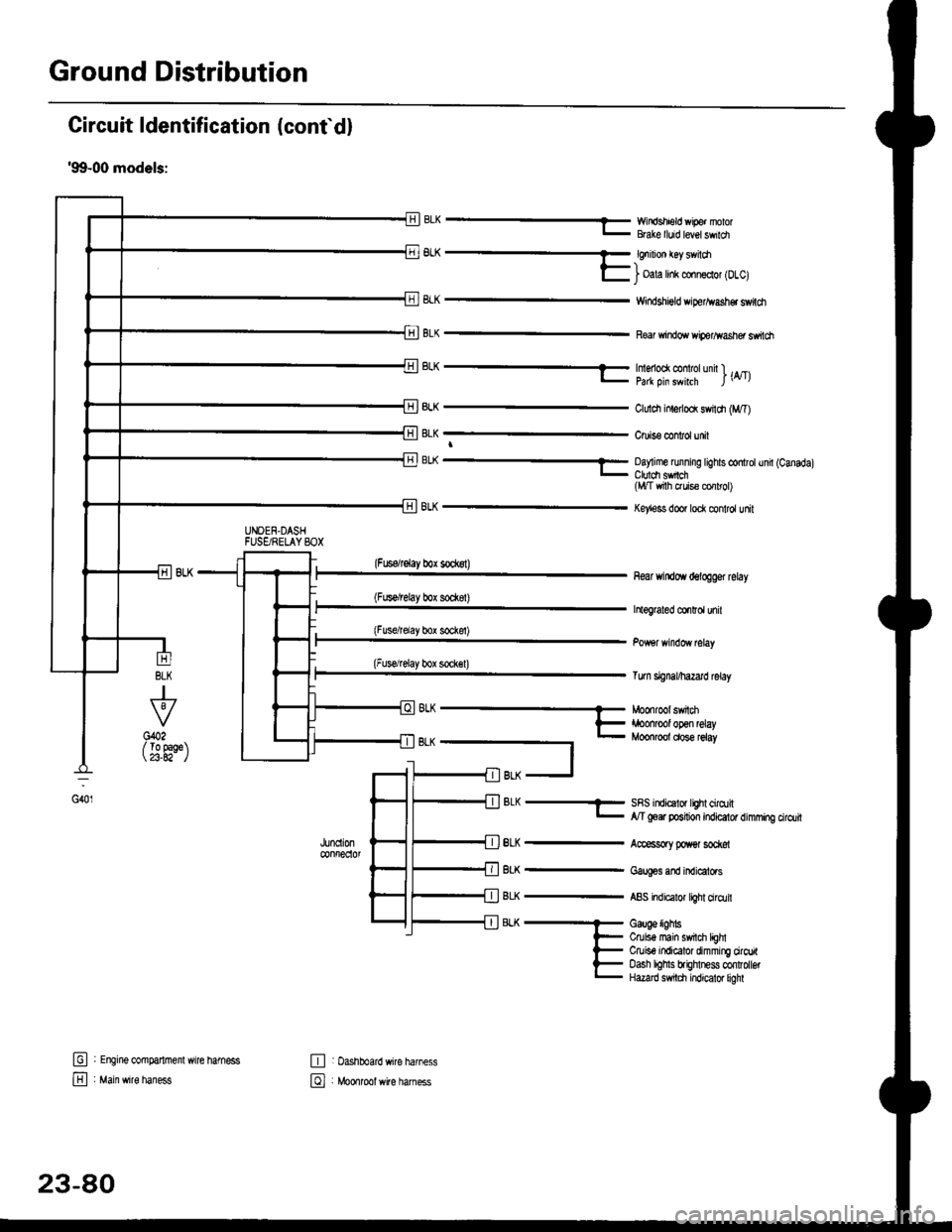
Circuit ldentification (conf d)
'99-00 models:
EWir'rdshield wipe. nolorBGke lluid level swildl
6L^ -- €nrnon €y sv loa-)l- i oala hnk conn€clol lDlcl
8LK
BLK
Windshigld dper^vash€r switdt
Re windo wiperlflasher ssitch
BLK
J
To 9aqe23.A2-
tr
E
UNOEN.DASHFUSgRELAYSOX
-r^ -..-- tmenoo( @ rotunn l ._.l- pa* oin swhrh l\4tl
ClLrldr inlerlod swildr (M,T)
Cruis€ confol unit
BL( ---- Oay me running tights controtund (Canadal_ Ctuldt sfich(l,t/T vrith ruis€ cor rol)
Key'ess door lock control unit
(Fuserelay box sockst)
(Fus€/relay box sod(8t)
(Fusdrelay bor sockel)
(Fuserelay box sock€l)
8LK
BLK
BLK
BLK
8LK
near windoYr delogger rclay
htograted co.Ird unil
Tum signal/hazard lelay
SRS indicalor lighl cirqtil,y'T goer position indicator dimming cirdlit
Accessory poxer sod@l
Gaug€s and indicators
ABS indicalor light ciro.lil
Gauge lighbCruis€ main swil$ lEhlCruiso indicator dimming ciroritoash lohls brighlness confolbtHazard s$tdl indicator liohl
G401
(
oh --- Moonroot swnm
t- iroonrool open relay- Moonroot dose reiay
t
fil BLK -J
: Engine @mparlrnenl wire hamess
: Main wire haness
,JUncll0n@nfreclol
E : Dashboard wire harness
El , Mo*tool *ite har"..
23-80
Page 1551 of 2189
![HONDA CIVIC 1997 6.G Owners Guide 96-98 models:
(wirh ABs)
oit
8LK - A/Tjear Posilion swilch
seNic€ check @nneclor
ABS Flmp motor
Audio unil
G552
@:fi-]
BLK - Powet doot lock @nlrolunil
i- D vet s doot lock aclualorl- P yg15 66611](/img/13/6068/w960_6068-1550.png "HONDA CIVIC 1997 6.G Owners Guide 96-98 models:
(wirh ABs)
oit
8LK - A/Tjear Posilion swilch
seNic€ check @nneclor
ABS Flmp motor
Audio unil
G552
@:fi-]
BLK - Powet doot lock @nlrolunil
i- D vet s doot lock aclualorl- P yg15 66611")
'96-98 models:
(wirh ABs)
oit
8LK - A/Tjear Posilion swilch
seNic€ check @nneclor
ABS Flmp motor
Audio unil
G552
@:fi-']
BLK - Powet doot lock @nlrolunil
i- D vet s doot lock aclualorl- P yg15 666110c1 swlgh
B" t ] po*er sindow man sw ch
E'0,'""a. *., *noo, ro,o,
Fuelunil
BLK-liJ#1!ll3n"**
E Healer sub'harness A
E : Healer sub harness B(cont'd)
23-A1
-r-r:=' r ,!r'-,
t/l
O -1:r'-
Dashboard wrre haness
U : Floor wire harness
E Drrve/s doorwire hamess
Page 1552 of 2189
![HONDA CIVIC 1997 6.G Owners Guide Ground Distribution
Circuit ldentification (contdl
99-00 models:(Wilholl ABS)
r1BL( -< 6 | c40. tFror oaoe 23-BC. II
L
E
UNDEF.H@DFUSF]RELAY BOX
_::I
A,/I gefi posilion swilchELD unil
Servi@ check](/img/13/6068/w960_6068-1551.png "HONDA CIVIC 1997 6.G Owners Guide Ground Distribution
Circuit ldentification (contdl
99-00 models:(Wilholl ABS)
r1BL( -< 6 | c40. tFror oaoe 23-BC. II
L
E
UNDEF.H@DFUSF]RELAY BOX
_::I
A,/I gefi posilion swilchELD unil
Servi@ check")
Ground Distribution
Circuit ldentification (cont'dl
'99-00 models:(Wilholl ABS)
r'1BL( -< 6 | c40. tFror oaoe 23-BC. II
L
E
UNDEF.H@DFUSF]RELAY BOX
_::I
A,/I gefi posilion swilchELD unil
Servi@ check connector
BL-_14BL- rl--{ry--Browe,mororreray
L4 ,r^ -.;--a-r,* -11-51 BLK - Hearer conrror o6nt n"*-fi-+aLx-lfuBLK- Hearer conrror panel
eLx -iff BLK - ff;?,m",:[:' "n'
or*
ABS glmp motor
_trl
G501
Pos€r door lock cortaol unitDivers door lock aclualorDriver's door lock switchLefl miror delogger
BLK --.+t _
F J Power wndos man swdch
-. Dive/s Fo*gr window motor
TBLK -.1 F--{ BLK - Fighr.niror detogger
tr
tr
E : Healer sub-haness A
El : Healer sub'harress B
: Floor wire hamess
: Drve/sdoorwife haness
-
|,-"*T-"^tl I
vl-L"."
G551
ort,
El ' Main *it" hanes
E : Dashboafd wirc harness
23-82
@ Passenger's doof w're hamess
Page 1630 of 2189
Integrated Gontrol Unit
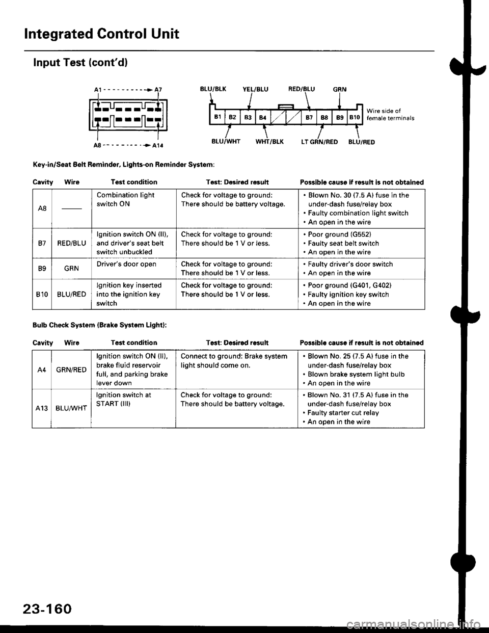
Input Test (cont'dl
A8--------.--all
Key-in/Seat Belt R€mind€r, Lights-on Reminder Systom:
Cavity WireTest condhion
Bulb Check System (Brako System Light):
Cavity WireTest condilion
Tost: D€sirod r€guh
T6st: Dosirad result
Possible cause if result is not obtained
Possibls cause if rasuft b not obtainod
A8
Combination light
switch ON
Check for voltage to ground;
There should be battery voltage.
Blown No.30 (7.5 A)fuse in the
under-dash fuse/relay box
Faulty combination light switch
An open in the wire
B7RED/BLU
lgnition switch ON (ll),
and driver's seat belt
switch unbuckled
Check for voltage to ground:
There should be 1 V or less.
Poor ground (G552)
Faulty seat belt switch
An open in the wire
B9GRNDriver's door openCheck for voltage to ground:
There should be 1 V or less.
. Faulty driver's door switch. An open in the wire
Bl0BLU/RED
lgnition key inserted
into the ignition key
switch
Check for voltage to ground:
There should be 1 V or less.
Poor ground (G401. G402)
Faulty ignition key switch
An open in the wire
A4GRN/RED
lgnition switch ON {ll),
brake fluid reservoir
full, and parking brake
tever oown
Connect to ground: Brake system
light should come on.
Blown No.25 (7.5 Alfuse in the
under-dash fuse/relay box
Blown brake system light bulb
An open in the wire
A13BLUA/1r'HT
lgnition switch at
START (III)Check for voltage to ground:
There should be battery voltage.
Blown No.31 (7.5 A) fuse in the
under-dash fuse/relay box
Faulty starter cut relay
An open in the wire
23-160
Page 1662 of 2189
Stereo Sound System
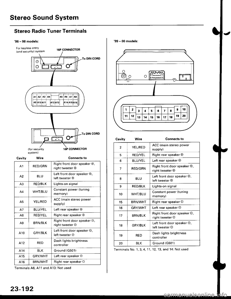
Stereo Radio Tuner Terminals
'96 - 98 models:
For keyless entry . t6p coNNEcroR(and securrty) syslem
To DIN CORD
To DIN CORD
(for securitysystem)
Cavity Wire
A1RED/GRNRight front door speaker o,
right tweeter @
BLULeft front door speaker @,
left tweeter @
A3RE D/B LKLights-on signal
A4WHT/BLUConstant power (tuning
memoryl
A5YEL/REDACC (main stereo power
suppry)
A7BLUI/ELLeft rear speaker O
A8RE DI/E LRight rear speaker O
A9BRN/BLKRight front door speaker O,
right tweeter o
A10GRY/BLKLeft tront door speaker O,
left tweeter O
412REDDash lights brightness
controller
A14BLKGround (G501)
415GRYMHTLeft rear speaker O
Al6BR N/VVHTRight rear speaker O
Terminals A6, A11 and A13: Not used
23-192
'99 - 00 models:
CsvityConnccts toWire
2YEL/REDACC (main stereo power
suppry)
5RE DI/E LRight rear speaker @
BLUI/ELLeft rear speaker @
7RED/GRNRight front door speaker @,
right tweeter @
8BLULeft front door speaker @,
left tweeter @
9RED/BLKLights-on signal
10WHT/BLUConstant power (tuning
memory)
15BRN,ryVHTRight rear speaker O
GRYMHTLeft rear speaker O
17BRN/BLKRight front door speaker O,
right tweeter O
18G RY/BLKLeft front door speaker O,
left tweeter O
'19REDDash lights brightness
controller
20BLKurouno t(l5u t,
Terminals No. 1, 3, 4, 11,12, 13, and 14: Not used
Page 1679 of 2189
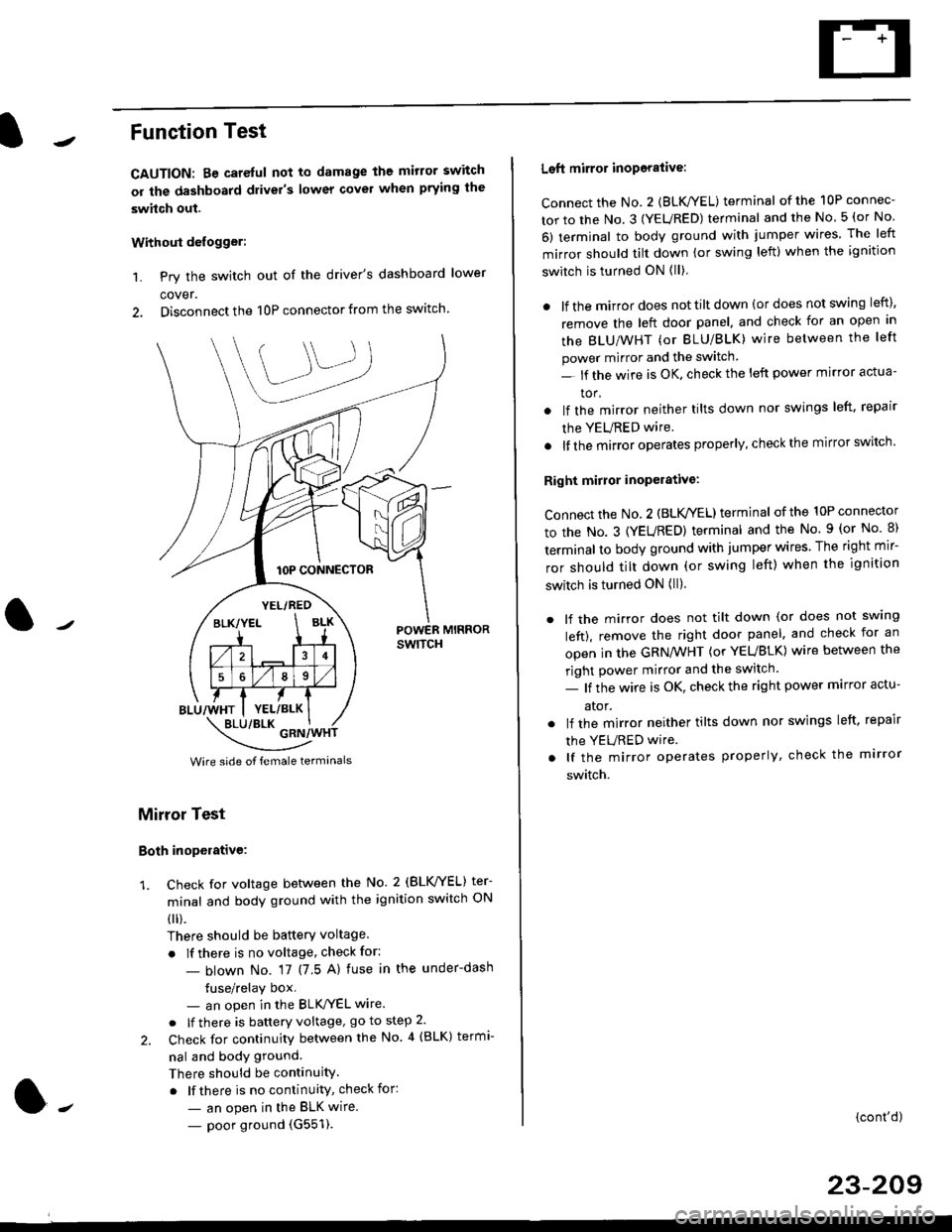
Function Test
CAUTION: Be careful not to damage the mirror switch
or the dashboard drivel's lower covel when prying the
swhch out.
Withoui defogger:
1. Pry the switch out of the driver's dashboard lower
cover.
2. Disconnect the 10P connector from the switch.
lOP CONNECTOR
BLU/WHT
YEL/RED
BLK/YELBLK
4
568
YEL/BLK
POWER MIRRORswtTcH
\:/"*jgil*-(
Wire side of female termanals
Mirror Test
Both inoperative:
1. check for voltage between the No. 2 (BLVYEL) ter
minal and body ground with the ignition switch ON
0 r).
There should be batterY voltage
. If there is no voltage, check for:
- blown No. 17 (7 5 A) fuse in the under-dash
tuse/relay box- an open in the BLK'/YEL wire.
o lf there is battery voltage, go to step 2.
2. Check for continuity between the No 4 (BLK) termi-
nal and body ground.
There should be continuity.
. lf there is no continuity, check for:
- an open in the BLK wire.
- poor ground (G551).
Left mirror inoporalive:
connect the No. 2 {BLK/YEL) terminal of the 10P connec-
tor to the No. 3 (YEURED) terminal and the No 5 (or No
6) terminal to body ground with jumper wires The left
mirror should tilt down (or swing left) when the ignition
switch is turned ON (ll)
. lf the mirror does not tilt down (or does not swing left),
remove the left door panel. and check for an open in
the BLU/WHT (or BLU/BLK) wire between the left
power mirror and the switch
- lf the wire is OK. check the left power mirror actua-
tor.
lf the mirror neither tilts down nor swings left. repair
the YEURED wire.
lf the mirror operates properly, check the mirror switch'
Right mirror inoperative:
Connect the No. 2 (BLK /EL) terminal of the 10P connector
to the No. 3 (YEURED) terminal and the No. 9 (or No 8)
terminal to body ground with jumper wires The right mir-
ror should tilt down (or swing left) when the ignition
switch is turned ON (ll).
. lf the mirror does not tilt down (or does not swlng
left), remove the right door panel. and check for an
open in the GRN/WHT (or YEUBLK) wire between the
right power mirror and the switch.
- lf the wire is OK, check the right power marror actu-
ator.
. lf the mirror neither tilts down nor swings left. repair
the YEURED wire
. lf the mirror operates properly, check the mirror
switch.
(cont'd)
23-209
Page 1683 of 2189
7.
8.
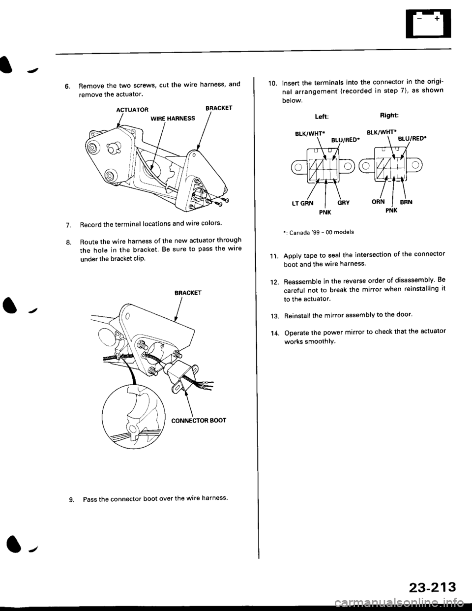
6. Remove the two screws, cut the wire harness, and
remove the actuator.
Record the terminal locations and wire colors'
Route the wire harness of the new actuator through
the hole in the bracket. Be sure to pass the wlre
under the bracket cliP.
BRACKET
9. Pass the connector boot over the wire harness
23-213
BLK/WHTi
,t
L,
.;{
I
oa
LT GRN I GRY
PNK
10, lnsert the terminals into the connector in the origi-
nal arrangement (recorded in step 7), as shown
Detow.
Right:
SLK/WHT*
BLU/REO'
": Canada '99 - 00 models
Apply tape to seal the intersection of the connector
boot and the wire harness.
Reassemble in the reverse order of disassembly Be
careful not to break the mirror when reinstalling it
to the actuator.
Reinstall the mirror assembly to the door.
Operate the power mirror to check that the actuator
works smoothlY.
Left:
11.
12.
13.
't 4.
PNK
Page 1727 of 2189
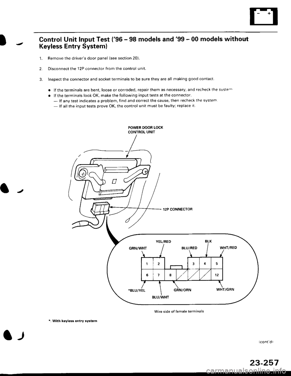
Control Unit Input Test ('96 - 98 models and'99 - 00 models without
Keyless Entry System)
1. Remove the driver's door panel (see section 20).
2. Disconnect the 12P connector from the control unit.
3. Inspect the connector and socket terminals to be sure they are all making good contact
a lf the terminals are bent, loose or corroded, repair them as necessary, and recheck the svste-
. lf the terminals look OK, make the following input tests at the connector.
- lf any test indicates a problem, find and correct the cause, then recheck the syslem
lf all the input tests prove OK, the control unit must be faulty; replace it.
.I2P CONN€CTOR
Wire side o{ femele terminals
*: With keyless entry system
l-llcont d)
23-257
YEL/RED
BLU/RED
15
1812
BLU/WHT
Page 1728 of 2189
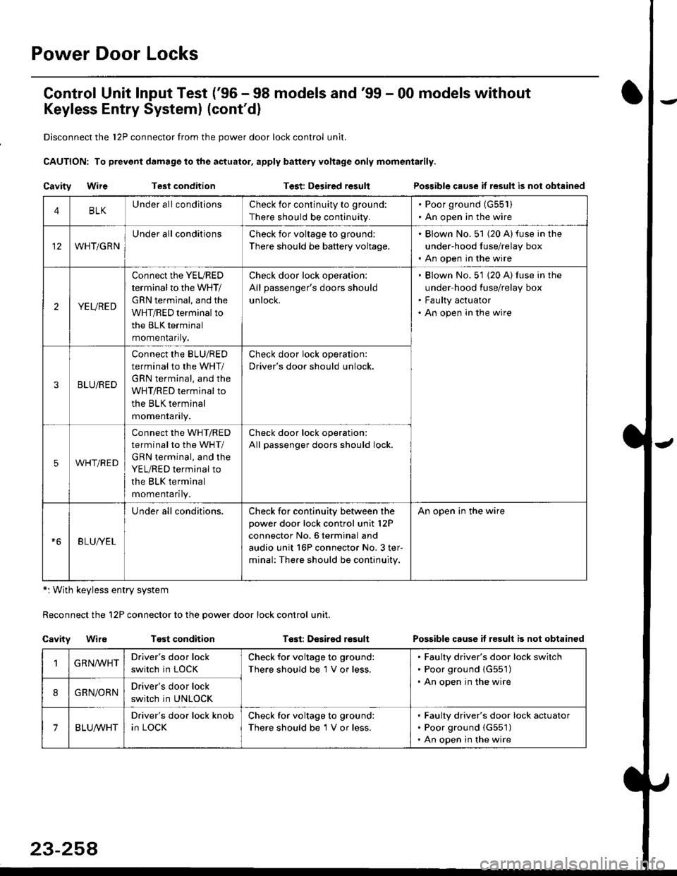
Power Door Locks
Control Unit lnput Test ('96 - 98 models and'99 - 00 models without
Keyless Entry Systeml (cont'dl
Disconnect the 12P connector from the power door lock control unit.
CAUTION: To prevsnt damage to the actuator, apply battery voltage only momentarily.
Cavity WireTest conditionTest: Desired resultPossible cause if result is nol obtained
*: With keyless entry system
Reconnect the 12P connector to the power door lock control unit.
Cavity WireTest conditionTssl: Desirsd losullPossible cause it resull b not obtained
4BLKUnder all conditionsCheck for continuity to ground:
There should be continuity.
. Poor ground (G55'l ). An open in the wire
WHT/GRN
Under all conditionsCheck for voltage to ground:
There should be battery voltage.
. Blown No. 51 (20 A)fuse in the
under-hood fuse/relay box. An open in the wire
2YEURED
Connect the YEURED
terminal to the WHT/
GRN terminal, and the
WHT/RED terminal to
the BLK terminal
momenraflty.
Check door lock operation:
All passenger's doors should
untocK.
Blown No. 51 {20 A) fuse in the
under-hood fuse/relay box
Faulty actuator
An open in the wire
3BLU/RED
Connect the BLU/RED
terminal to the WHT/
GRN terminal. and the
WHT/RED terminal to
the BLK terminal
momenraflry.
Check door lock operation:
Driver's door should unlock.
5WHT/RED
connect the WHT/RED
terminal to the WHT/
GRN terminal, and the
YEL/RED terminal to
the BLK terminal
momenrafl ty.
Check door lock operation:
All passenger doors should lock.
BLU/YEL
Under all conditions.Check for continuity between the
power door lock control unit l2P
connector No. 6 terminal and
audio unit 16P connector No. 3 ter-
minal: The.e should be continuity.
An open in the wire
GRN,ryVHTDriver's door lock
switch in LOCK
Check for voltage to ground:
There should be 1 V or less.
Faulty driver's door lock switch
Poor ground {G551)
An open in the wire
8GRN/ORNDriver's door lock
switch in UNLOCK
7BLUA/VHT
Driver's door lock knob
in LOCK
Check for voltage to ground:
There should be 1 V or less.
Faulty driver's door lock actuator
Poor ground {G551)
An open in the wire