Wire door HONDA CIVIC 1997 6.G Repair Manual
[x] Cancel search | Manufacturer: HONDA, Model Year: 1997, Model line: CIVIC, Model: HONDA CIVIC 1997 6.GPages: 2189, PDF Size: 69.39 MB
Page 1863 of 2189
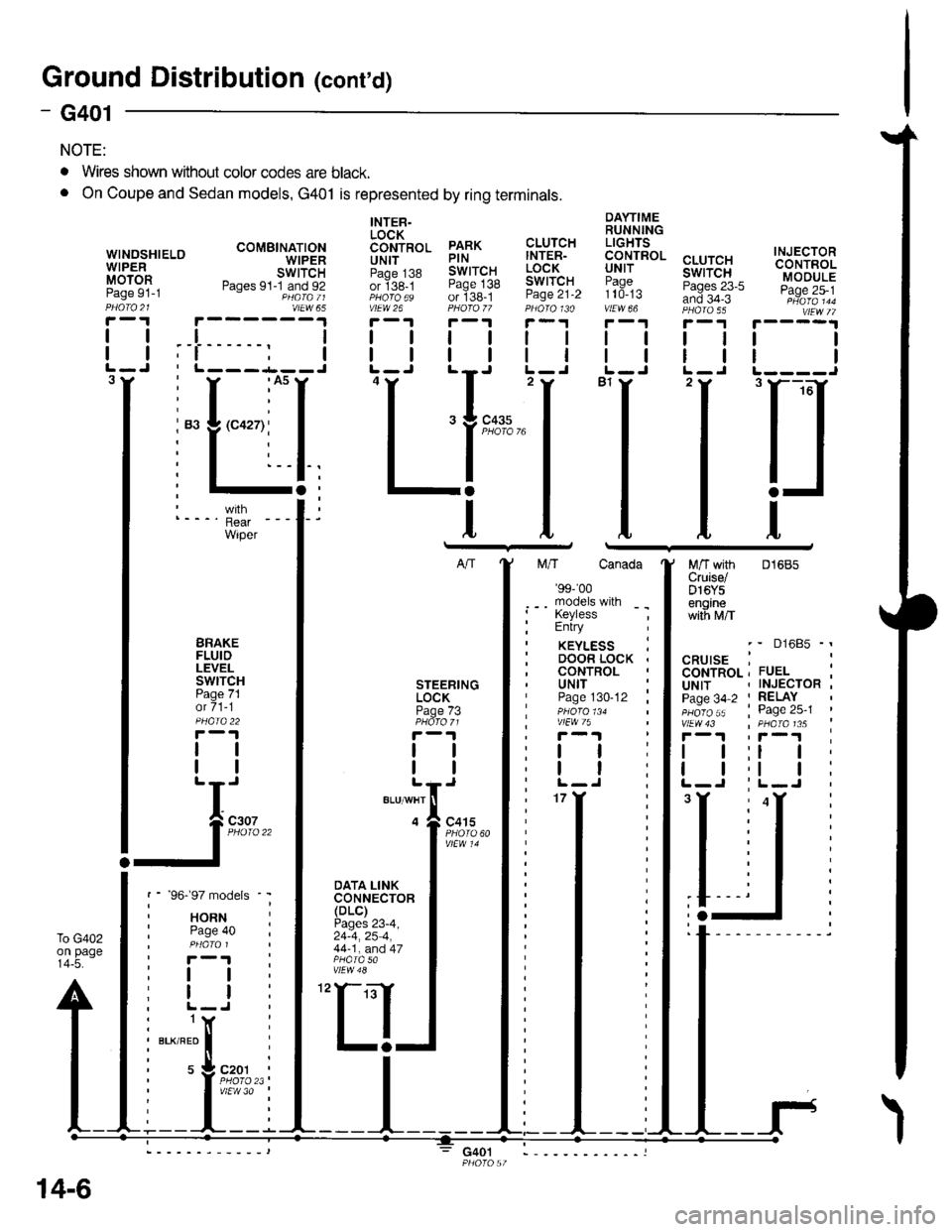
Ground Distributioh (conrd)
)
- G401
NOTE:
To G402on page14-5.
WINOSHIELOWIPERMOTORPage 91-1
DAYTIMERUNNINGLIGHTS
99.!rRoL cLUrcHuNr I swtTcH:?99^ Pases 23-5and 34-3vtEw 66 PHA|A 55
I
I
INJECTORCONTROLMODULEPage 25-1
I
I
3
. Wires shown without color codes are black.
o On Coupe and Sedan models, G401 is represented by ring terminals.
tl
tl
INTER.LOCK6611p99 PARKUN|T PINpaoe j38 SWITCHor ige_t Page 138PHoro6s of 138-1vtEw 26 PHOfO /7r-1 r-'t
tttl
CLUTCHINTER-LOCKSWITCHPage 21-2
ll
ll
ttl
rll
I
Itttl
'Ll;
I
n
t
M/T with 01685Cruise/D16Y5enginewith M/T
BRAKEFLUIDLEVELswtTcHPage 71ot 71-1
tl
tl
DOOR LOCK .CONTROLSTEERINGLOCKPage /3
tl
tl
UNITPage 130-12 ;
ttl
tt:
models
RNte 40
I
I
(
I
I czor
l'i1l?,
'97 mo
HORNPage 4
I
I
NFnl
s 9c.Plv'
BLK/RED
t
IJ;--
',f-l
DATA LINKCONNECTOR(DLC)Pages 23-4,24-4,25 4,44-1, and 47
30
14-6
G401
Page 1865 of 2189
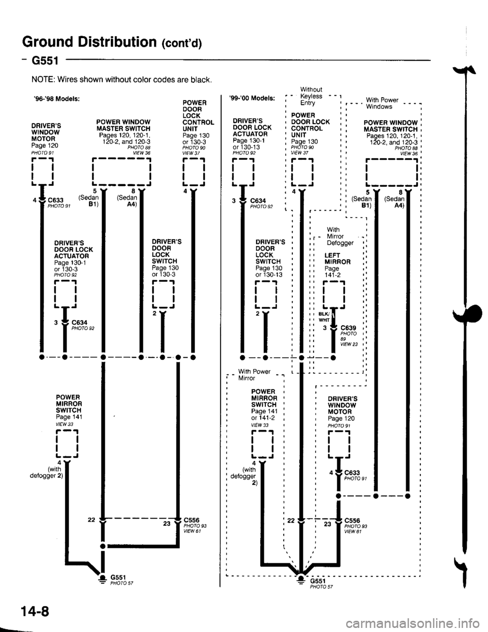
Ground Distribution (cont'd)
1
- G551
Page
I
I
'96-'98 Models:
DRIVER'SwtNDowMOTOR
NOTE: Wires shown without color codes are black.
4
12091
I
I
c633
oRrvER'sDOOR LOCKACTUATORPage 130-1or 130-3
tl
tl
:f ;'*"
.--a ----
sl)
POWER WINDOWMASTER SWITCHPages 120, 120-1,120-2, and 120-3PHO|O AAvlEW 36
tl
tlL-----J
POWERDOORLOCKCONTROLUNITPage 130or 130-3
vlEW3/
tl
tl
4
c556
vtEw 61
8(SedanA4)
DRIVER'SDOORLOCKswrTcHPage 130or 130-3
tl
tl
,I
'-.o -.o -
POWERMIRRORswrTcHPage 141vlEw 33
ll
tl
4(withdefogger 2)
G55t
14-8
Page 1941 of 2189
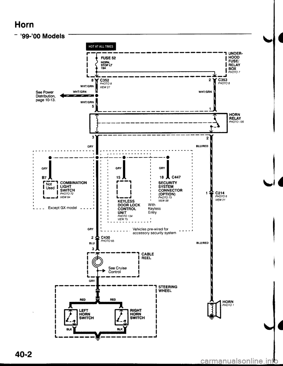
Horn
- '99-'00 Models
FUSE 52HORI,SfOP LTt5a
UNDER.HOODFUSE/RELAYBOX
HORNRELAY
2
BIU/FED
Ior
GRY
.,1 ,
J---a-----r---O
i ;l i ;,1...,' r--1 : SECUR|TY:ll:sYsrEM,ia,coNNEcroR' ! ! (oPrloN), L--J , i!,o!o 73, KEYLESS I vlEw 58
: DooR LocK withi coNTRoL Kevless, UNIT EntryI PHOIO 134I vtEw 75
i o.--------;
:T:' cnvl :
i"l ii ri-'--.| coMBtNATtoN
: lrft ! !',f,11" I' | | puotozz :', l--J vttw u ;
i--- Er""pt ex.ooer ----j
c214
v|EW21
c430PHOTO 65
Vehicles pre-wired foraccessory security system
STEERINGWHEEL
CABLEREEL
.l
I
I
I
ISee CruiseControl
GRY
ELU
I
a\
I
GRY
HORN
---------^1
niffil"a!m"
40-2
Page 1994 of 2189
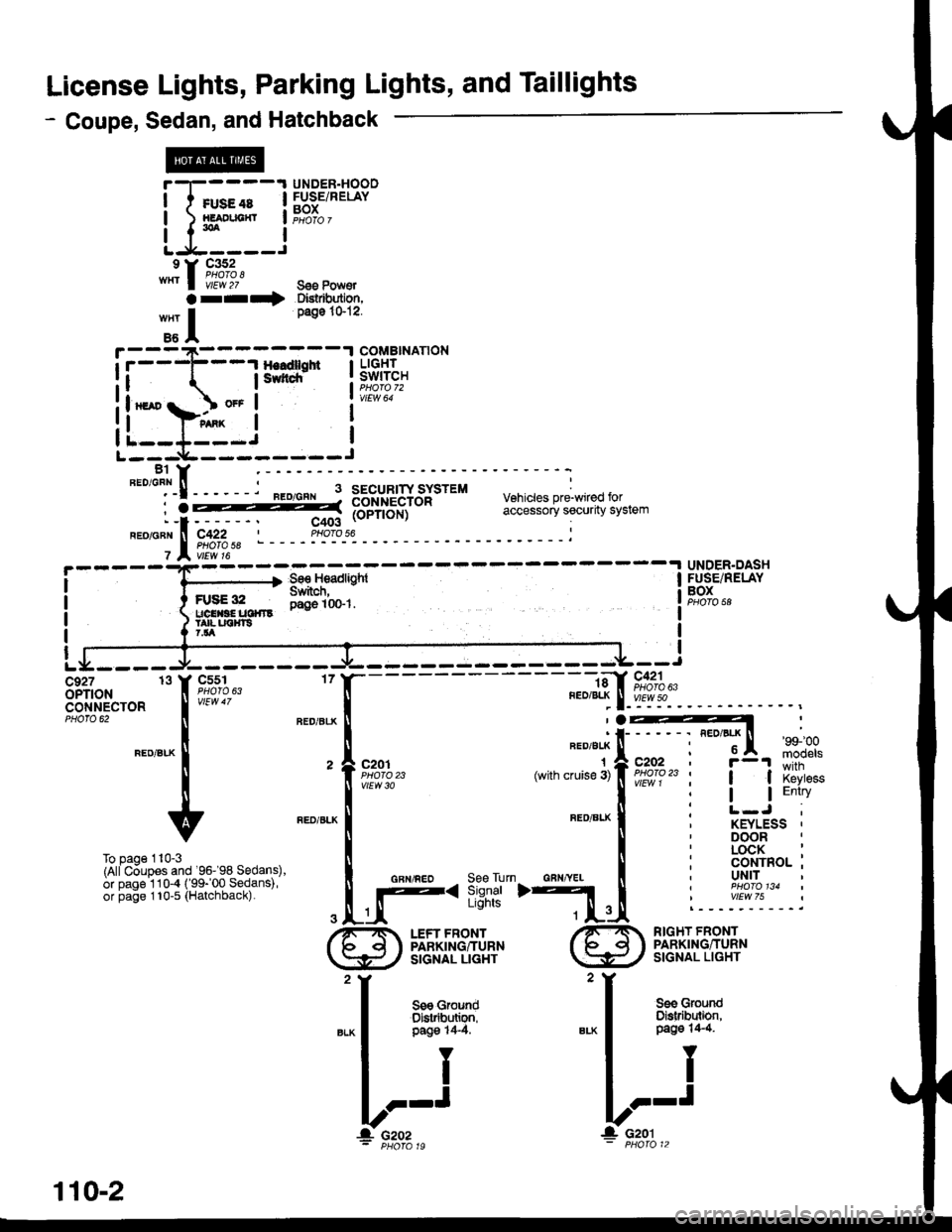
License Lights, Parking Lights, and Taillights
- Coupe, Sedan, and Hatchback
I I rusecs I
Li5:_i
"^1,1fr!;?'
arr*
HI
UNDER.DASHFUSE/RELAYBOX
UNDER.HOOOFUSE/RELAYBOX
g€o Pow€rDlstrbutiofl,page 101?.
B1 YFED/GFN ll-- -
:t! - - - '--:gsg-l 3totur['JY3;tttu vehicres pre'wired tor
: -i::-- - - -. c;A (oPrroN) ceucssu'Yir
neoionlr lf C422 | Ptloro 56I PHorc 587 A, vtEw t6
-)' 56€. Hsadlqht I
FUsEsr lYi-"'l;-. I
:]% ropnor.rt cLlEssv'v .evu"rt JtJre"'
ru9c ltz DaO€ 10$1.uclrlaEtlclllS -
ta{- uotfls7.lla
c927 13 Y CssloPTfoN I ltlglo 63
clNl.rEcroR I
-" "'
tFEoiEL( |
II
v
To Daoe 110-3(AliC6upes and '96- 98 Sedans),or page 1 10-4 ( 99- 00 Sedans),or page 110-5 (Halchback)
FED/8LK
1(with cruise 3)
RED/BLI(
GAN/YEI
AED/ELX'99100
moqelsc202r -'! wiiri| | xtYess
I I EntryI
KEYLESS '
DOORLOCK :CONTROL ;UNIT
RIGHT FRONTPARKING/TURNSIGNAL LIGHT
L.-r
/-1M LEFT FRONTfb d I PARKTNGIuRN
\Y,Z slcNAL LlcHr
'I
see Ground
"* | 3$l''Tll
II
l.?'J
! czoz- PHOfa 19
110-2
Page 2026 of 2189
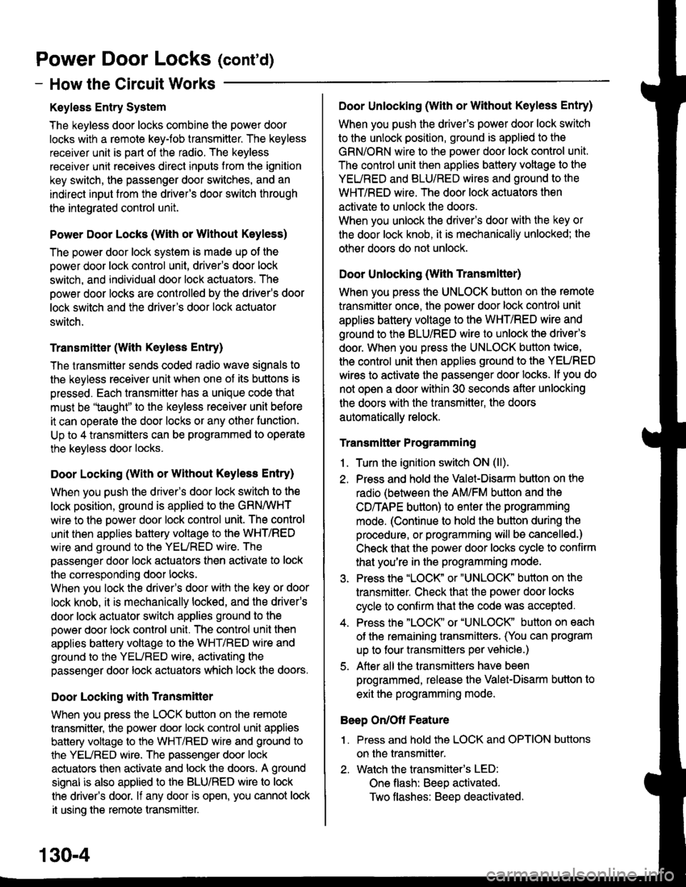
Power Door Locks (cont'd)
- How the Circuit Works
Keyless Entry System
The keyless door locks combine the power door
locks with a remote keyJob transmitter. The keyless
receiver unit is part of the radio. The keyless
receiver unit receives direct inputs f rom the ignition
key switch, the passenger door switches, and an
indirect input trom the driver's door switch through
the integrated control unit.
Power Door Locks (With or Wlthout Keyless)
The power door lock system is made up of the
oower door lock control unit. driver's door lock
switch, and individual door lock actuators. The
power door locks are controlled by the driver's door
lock switch and the driver's door lock actuator
switch.
Transmitter (With Keyless Entry)
The transmitter sends coded radio wave signals to
the keyless receiver unit when one ot its buttons is
pressed. Each transmitter has a unique code that
must be 'laught" to the keyless receiver unit before
it can operate the door locks or any other lunction.
Up to 4 transmitters can be programmed to operate
the keyless door locks.
Door Locking (With or without Keyless Entry)
When you push the driver's door lock switch to the
lock position, ground is applied to the GBN/IVHT
wire to the oower door lock control unit. The control
unit then applies battery voltage to the WHT/RED
wire and ground to the YEURED wire. The
passenger door lock actuators then activate to lock
the corresponding door locks.
When you lock the driver's door with the key or door
lock knob, it is mechanically locked, and the driver's
door lock actuator switch applies ground to the
oower door lock control unit. The control unit then
applies battery voltage to the WHT/RED wire and
ground to the YEURED wire, activating the
passenger door lock actuators which lock the doors.
Dool Locking with Transmitter
When you press the LOCK button on the remote
transmitter, the power door lock control unit applies
battery voltage to the WHT/RED wire and ground to
the YEURED wire. The passenger door lock
actuators then activate and lock the doors. A ground
slgnal is also applied to the BLU/RED wire to lock
the driver's door. lf any door is open, you cannot lock
it using the remote transmitter.
Door Unlocking (With or Without Keyless Entry)
When you push the driver's power door lock switch
to the unlock position, ground is applied to the
GRN/ORN wire to the power door lock control unit.
The control unit then applies battery voltage to the
YEURED and BLU/RED wires and ground to the
WHT/RED wire. The door lock actuators then
activate to unlock the doors.
When you unlock the driver's door with the key or
the door lock knob, it is mechanically unlocked; the
other doors do not unlock.
Door Unlocking (With Transmltter)
When you press the UNLOCK button on lhe remote
transmitter once. the power door lock control unit
applies battery voltage to the WHT/RED wire and
ground to the BLU/RED wire to unlock the driver's
door. When you press the UNLOCK button twice,
the control unit then applies ground to the YEURED
wires to activate the passenger door locks. lf you do
not open a door within 30 seconds after unlocking
the doors with the transmitter, the doors
automatically relock.
Transmltter Programming
1 . Turn the ignition switch ON (ll).
2. Press and hold the Valet-Disarm button on the
radio (between the AM/FM button and the
CD/TAPE button) to enter the programming
mode. (Continue to hold the button during the
procedure, or programming will be cancelled.)
Check that the power door locks cycle to confirm
that you're in the programming mode.
3. Press the "LOCK' or "UNLOCK' button on the
transmitter. Check that the power door locks
cycle to confirm that the code was accepted.
4. Press the "LOCK" or "UNLOCK" button on each
of the remaining transmitters. (You can program
up to four transmitters per vehicle.)
5. After all the transmitters have been
programmed, release lhe Valet-Disarm button to
exit the programming mode.
Beep On/Oft Feature
'I . Press and hold the LOCK and OPTION buttons
on the transmitter.
2. Watch the transmitter's LED:
One flash: Beeo activated.
Two tlashes: Beeo deactivated.
130-4
Page 2028 of 2189
Power Door Locks (cont'd)
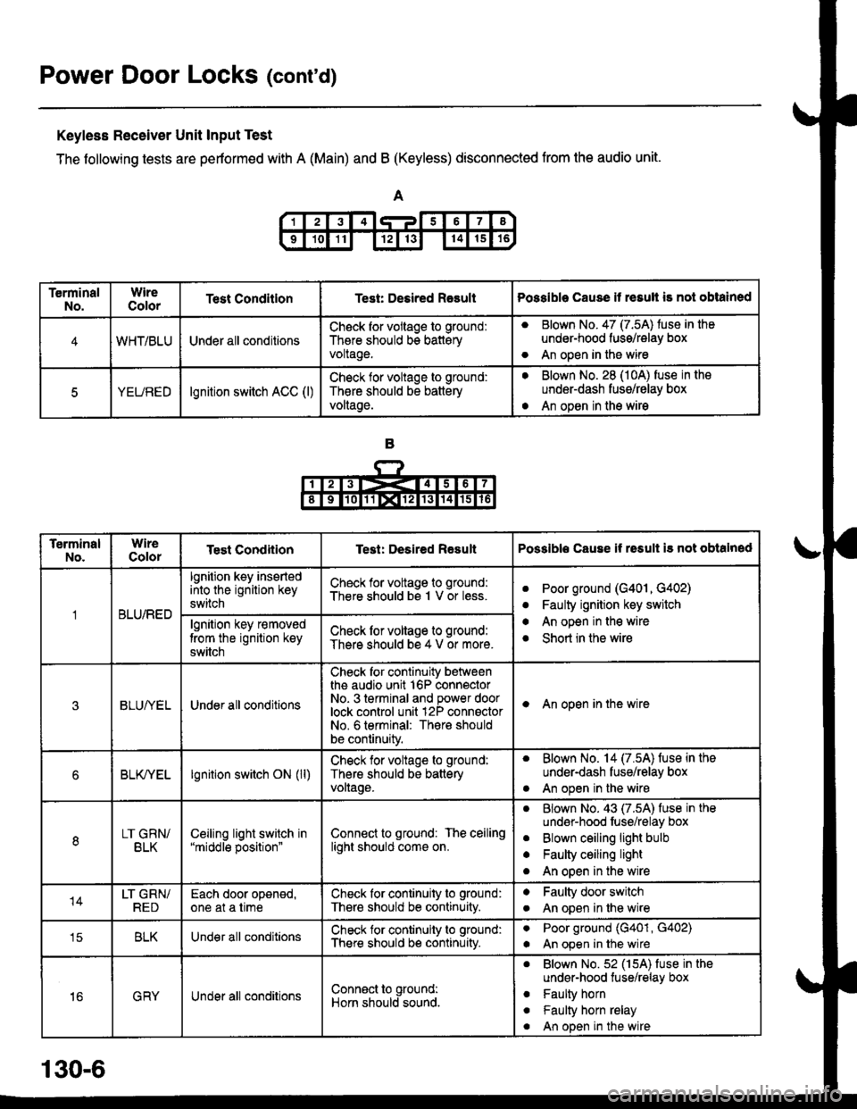
Keyless Receiver Unit Input Test
The following tests are pertormed with A (Main) and B (Keyless) disconnected from the audio unit.
TerminalNo.WireColorTest ConditlonTest: Desired RasultPossible Cause it resull is not obtained
4WHT/BLUUnder all conditionsCheck for vollage to ground:
There should bs batteryvoltage.
aBlown No. 47 (7.5A) tuse in the
under-hood fuss/relay box
An open in the wireo
5YEUREDlgnition switch ACC (l)Check lor voltage to ground:
Th€re should be battery
voltage.
aBlown No. 28 (10A) fuse in the
underdash fusg/relay box
An open in the wirea
TerminalNo.WireColorTest CondiiionTest: Desired ResultPossible Cause if rssult i3 not obtalned
BLU/RED
lgnition key insertedinto the ignition key
switch
Check for voltage to ground:
There should bs 1 V or less.aPoor ground (G401, G402)
Faulty ignition key switch
An open in the wire
Short in the wire
a
a
algnition key r€moved
trom the ignition key
switch
Check lor voltage to ground:
There should be 4 V or more.
3BLUI/ELUnder all conditions
Check for continuity betweenthe audio unit 16P connectorNo- 3 terminal and power doorlock control unit 12P connsctorNo. 6 terminal: There should
be continuity.
I An open in the wire
6BLK/YELlgnition switch ON (ll)Check for voltage to ground:
Thers should be batteryvollage.
. Blown No. 14 (7.5A) fuse in the
under-dash fuse/relay box
. An open in the wire
8LT GRN/BLKCeiljng light switch in"middle position"Connect to ground: The ceilinglight should come on.
aBlown No. 43 (7.5A) fuse in the
undsr-hood fuse/relay box
Blown ceiling light bulb
Faulty ceiling light
An open in the wire
a
a
o
14LT GRN/REDEach door oponed,one at a timeCheck for continuity to ground:
There should be continuity.
aFaulty door switch
An open in lhe wirea
tcBLKUnder all conditionsCheck for continuity to ground:
There should b€ continuity.
aPoor ground (G401, G402)
An open in the wirea
16GRYUnder all conditionsConn€ct to ground:
Horn should sound.
. Blown No.52 (15A) fuse in the
under-hood tuse/relay box
. Faulty horn
. Faulty horn relay
. An open in the wire
130-6
Page 2029 of 2189
 reconnected to the audio unit.
B
\
TerminalNo.WireColorTest CondilionTest: Desired ResultPossible Cause it result is not obtained
9GRN/ORN
Drivers do")
\
The following tests are performed with A (Main) reconnected to the audio unit.
B
\
TerminalNo.WireColorTest CondilionTest: Desired ResultPossible Cause it result is not obtained
9GRN/ORN
Driver's door lockswitch in UNLOCKCheck tor voltage to ground:There should be l V or less.
o Poor ground (G551)
. Faulty driver's door lock switch
. An open in the wire
. Short in the wire
Driver door lockswitch in LOCKCheck for voltage to ground:
There should be 4 V or more.
10GRN/vvHT
Driver's door lockswitch in UNLOCKCheck for voltage to ground:
There should be 4 V or more.
r Poor ground (G551)
. Faulty driver's door lock switch
o An open in the wire
o Short in the wire
Driver's door lockswitch in LOCKCheck for voltage to ground:
There should be 1 V or less.
\
130-7
Page 2031 of 2189
\,113. Recheck with a known good transmitler
reprogrammed to the vehicle. Does the system
work properly in all modes?
Yes - Replace the transmitter and program it by
using the procedure on page 130-4.
No - ReDlace the radio.
\lr
\
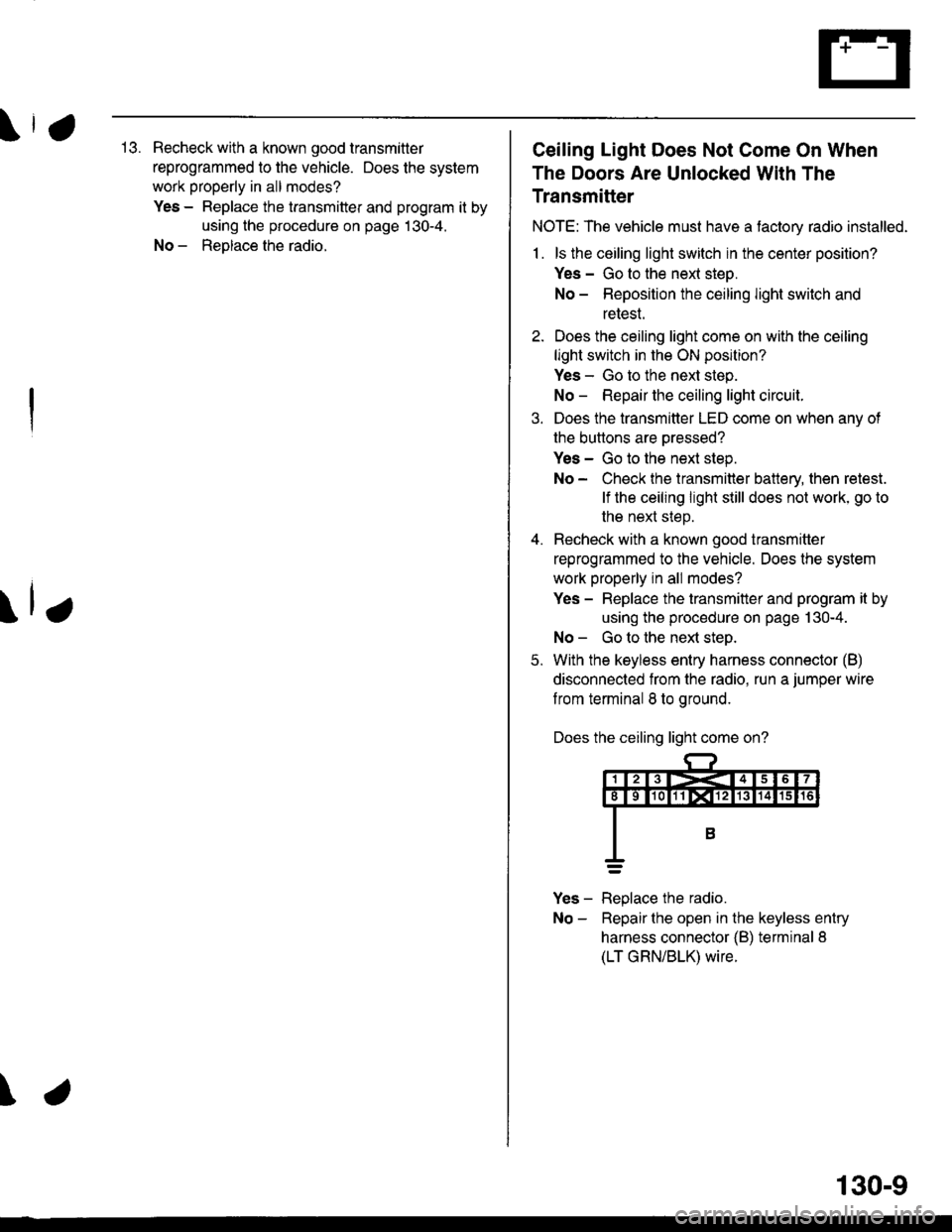
Ceiling Light Does Not Come On When
The Doors Are Unlocked With The
Transmitter
NOTE: The vehicle must have a tactory radio installed.
1 . ls the ceiling light switch in the center position?
Yes - Go to the nexl steo.
No - Reposition the ceiling light switch and
retest.
2. Does the ceiling light come on with the ceiling
light switch in the ON position?
Yes - Go to the next step.
No - Repair the ceiling light circuit.
3. Does the transmitter LED come on when anv of
the buttons are oressed?
Yes - Go to the next step.
No - Check the transmitter battery, then retest.
lf the ceiling light still does not work, go to
the next steD.
4. Recheck with a known good transmitter
reprogrammed to the vehicle. Does the system
work properly in all modes?
Yes - Replace the transmitter and program it by
using the procedure on page 130-4.
No - Go to the ne)d steo.
5. With the keyless entry harness connector (B)
disconnected from the radio. run a jumper wire
f rom terminal 8 to ground.
Does the ceiling light come on?
Yes - Replace the radio.
No - Repairthe open in the keyless entry
harness connector {B) terminal 8
(LT GRN/BLK) wire.
130-9
Page 2032 of 2189
Power Door Locks (contd)
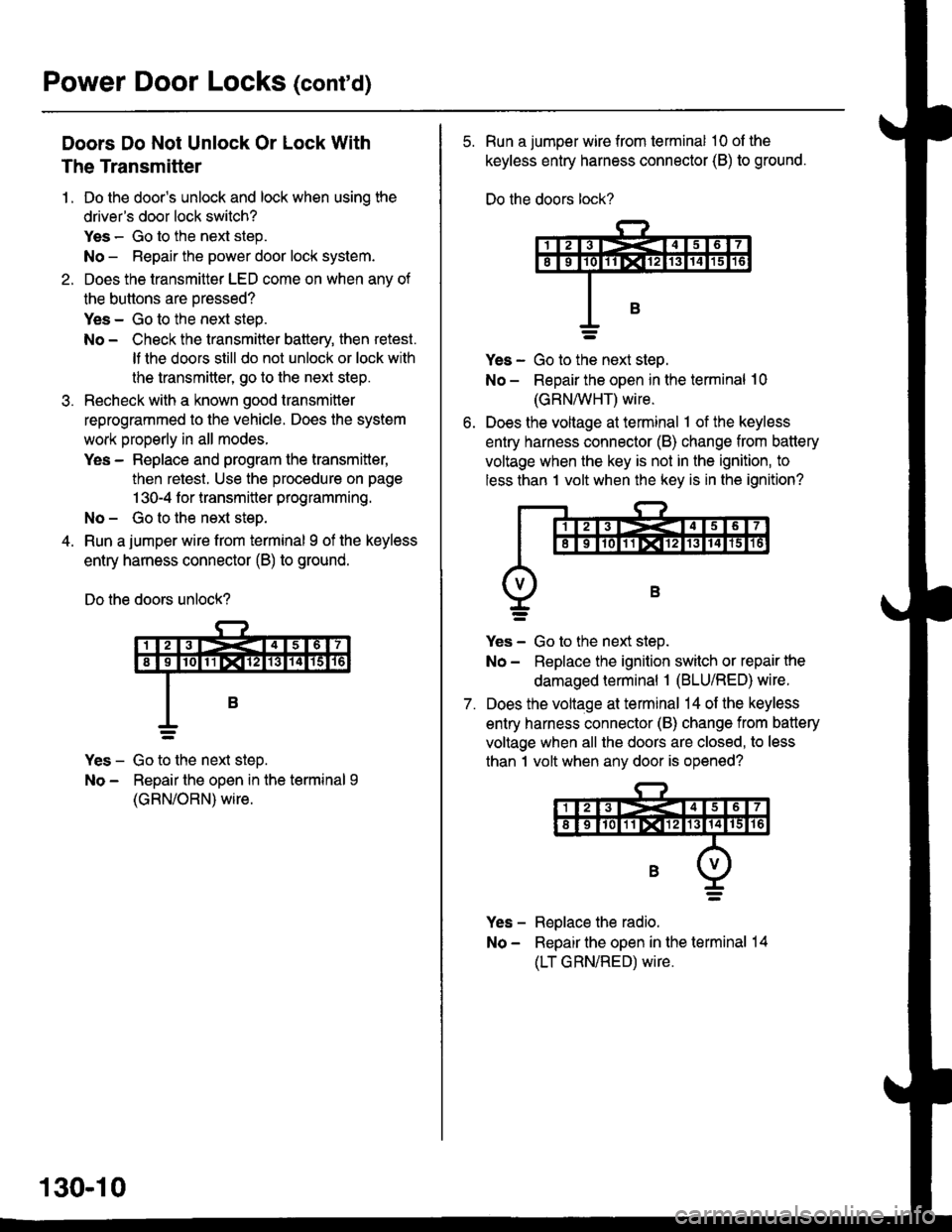
Doors Do Not Unlock Or Lock With
The Transmitter
1. Do the door's unlock and lock when usinq the
driver's door lock switch?
Yes - Go to the next step.
No - Repair the power door lock system.
2. Does the transmitter LED come on when anv of
the buttons are oressed?
Yes - Go to the next steo.
No - Check the transmitter battery, then retest.
It lhe doors still do not unlock or lock with
the transmitte( go to the next step.
Recheck with a known good transmitter
reprogrammed to the vehicle. Does the system
work properly in all modes.
Yes - Replace and program the transmitter,
then retest. Use the procedure on page
1 30-4 f or transmitter programming.
No- Gotothe next step.
Run a jumper wire from terminal I of the keyless
entry harness connector (B) to ground.
Do the doors unlock?
Yes - Go to the next steD.
No - Repair the open in the terminal 9
(GRN/ORN) wire.
130-10
5. Run a jumper wire from terminal 10 ol the
keyless entry harness connector (B) to ground.
Do the doors lock?
ves - Go to ttie next steo.
No - Repair the open in the terminal 10
(GRN/vVHT) wire.
Does the voltage at terminal 1 of the keyless
entry harness connector (B) change from battery
voltage when the key is not in the ignition, to
less than 1 volt when the key is in the ignition?
7.
Yes - Go to the next step.
No - Replace the ignition switch or repair the
damaged terminal 1 (BLU/RED) wire.
Does the voltage at terminal 14 of the keyless
entry harness connector (B) change from battery
voltage when all the doors are closed, to less
than 1 volt when any door is opened?
Yes - Replace the radio.
No - Repair the open in the terminal 14
(LT GRN/RED) wire.
Page 2036 of 2189
Power Door Locks (conrd)
- How the Circuit Works
Keyless Entry System
The keyless door locks combine the power door
locks with a remote key-fob transmitter. The keyless
door lock control unit receives direct inputs from the
ignition key switch, the passenger door switches,
and an indirect inDut from the driver's door switch
through the integrated control unit.
Power Door Locks
The power door lock system rs made up ot the
keyless door lock control unit, driver's door lock
switch, and individual door lock actuators. The
power door locks are controlled by the driver's door
lock switch and the driver's door lock actuator
switch.
Transmittel
The transmitter sends coded radio wave signals to
the keyless door lock conlrol unit when one of its
buttons is pressed. Each transmitter has a unique
code that must be 'laught" to the conlrol unit before
it can operate the door locks or any other function.
Up to 4 transmitters can be programmed to operate
the keyless door locks.
Door Locking
When you push the driveas door lock switch to the
lock position, ground is applied to the GRNMHT
wire to the keyless door lock control unit. The
control unit then applies battery voltage to the
WHT/RED wire and ground to the YEURED wire.
The passenger door lock actuators then activate to
lock the corresponding door locks.
When you lock the dnver's door with the key or door
lock knob, it is mechanically locked, and the driver's
door lock actuator switch applies ground to the
oower door lock control unit. The control unit then
applies battery voltage to the WHT/RED wire and
ground to the YEURED wire, activating the
passenger door lock actuators which lock the doors.
Door Locking with Transmitter
When you press the LOCK button on the remote
transmitter, the keyless door lock control unil applies
battery voltage to the WHT/RED wire and ground to
the YEURED wire. The passenger door lock
actuators then activate and lock the doors. A ground
signal is also applied to the BLU/RED wire to lock
the driver's door. lf any door is open, you cannot lock
it using the remote transmitter.
Door Unlocking
When you push the driver's power door lock switch
to the unlock position, ground is applied to the
GRN/ORN wire to the keyless door lock control unil.
The control unit then applies battery voltage to the
YEUREO and BLU/RED wires and oround to the
WHT/RED wire. The door lock actuators then
activate to unlock the doors.
When you unlock the driver's door with the key or
the door lock knob, it is mechanically unlocked; the
other doors do not unlock.
Door Unlocking with Transmitter
When you press the UNLOCK button on the remote
transmitter once, the keyless door lock control unit
applies battery voltage to the WHT/RED wire and
ground to the BLU/RED wire to unlock the driver's
door. When you press the UNLOCK button twice,
the control unit then applies ground to the YEURED
wires lo activate the passenger door locks. lf you do
not open a door within 30 seconds after unlocking
the doors with the transmitter, the doors
automatically relock.
Transmitter Programming
. Entering the programming mode cancels all
learned transmitter codes, so none of the
previously programmed transmitters will work.
You must reprogram all the transmitters once
you're in the programming mode.
. To keep the system from exiting the
programming mode, complete each step within 5
seconds of the previous step, and program the
transmitters within 10 seconds of each other.'1 . Turn the ignition switch ON (ll).
2. Press the "LOCK" or "UNLOCK" button on one
of the transmitters. (A non-programmed
transmitter can be used for this step.)
3. Turn the ignition switch OFF (0).
4. Repeat steps 1, 2, and 3 two more times with
the transmitter used in step 2.
5. Turn the ignition switch ON (ll).
6. Press the "LOCK" or "UNLOCK" button on the
same transmitter. Check that the power door
locks cycle to confirm that you're in the
programmrng mooe.
7. Press the "LOCK" or "UNLOCK" button on each
lransmitter. (You can program up to four
lransmitters per vehicle.) Check that the power
door locks cycle after you push each transmitter
button, contirming that the system has accepted
the transmitter's code.
Beep On/Off Feature
1 . Press and hold the LOCK and OPTION buttons
on the transmitter.
2. Watch the transmitter's LED:
One flash: BeeD activated.
Two flashes: Beep deactivated.
130-14