cylinder HONDA CIVIC 1998 6.G Owners Manual
[x] Cancel search | Manufacturer: HONDA, Model Year: 1998, Model line: CIVIC, Model: HONDA CIVIC 1998 6.GPages: 2189, PDF Size: 69.39 MB
Page 436 of 2189
I
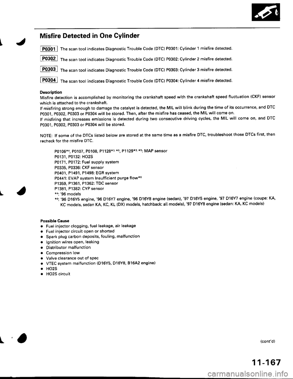
Misfire Detected in One Cylinder
P0301 | The scan tool indicates Diagnostic Trouble Code (DTC) P0301: Cylinder 1 misfire detected.
[F03O2l 16"""untool indicates Diagnostic Trouble code (DTc) P0302: Cylinder2 misfire detected.
[FO3Ofl 16" ".un toot indicates Diagnostic Troubte Code (DTC) P0303; Cylinder 3 misfire detected.
I P0304 I ths..rr tool indicates Diagnostic Trouble Code (DTC) PO3O4: Cylinder 4 misfire detected.
D€scription
lMisfire detection is accomplished by monitoring the crankshaft speed with the crankshaft speed fluctuation (CKF) sensor
which is attached to the crankshaft,
lf misfiring strong enough to damage the catalyst is detected, the MIL will blink during the time of its occurrence, and DTC
PO3O1, P0302, PO3O3 or P0304 will be stored. Then, after the misfire has ceased, the MIL will come on.
lf misfiring that increases emissions is detected during two consecutive driving cyclss, the MIL will come on, and DTC
P0301, P0302, P0303 or P0304 will be stored.
NOTE: lf some of the DTCS listed below are stored at the same time as a misfire DTC, troubleshoot those DTCS first, then
recheck for the misfire DTC.
PO106*1, P0107, P0108. P1128*3'*5, P1129*3'*5: MAP sensor
P0131, P0132: HO2S
P0171, P0172iFuel suppiy system
P0335, P0336: CKF sensor
P0401. P1491, P1498: EGR system
P0441: EVAP system Insufficient purge flow*6
Pl359. P1361. Pl362: TDC sensor
P1381. Pl382: CYP sensor*o: '96 models*6: '96 D16Y5 engine,'96 D16Y/ engine,'96 D16Y8 engine {sedan),'97 D16Y5 engine,'97 D16\4, engine (coupe: KA,
KC models, sedan KA. KC, KL (DX) models, hatchback:all models),'97 D16Y8 engine (sedan: KA, KC models)
Possible Cause
. Fuel injector clogging, fuel leakage, air leakage
. Fuel injector circuit open or shorted
. Spark plug carbon deposits, fouling, malfunction
. lgnition wires open. leaking
. Distributor malfunction
. ComDression low
. Valve clearance out of spec
. VTEC system malfunction (D16Y5, D16Y8. 81642 engine)
. HO2S
. HO2S circuit
(cont'd)
11-167
r'a
Page 437 of 2189
PGM-FI System
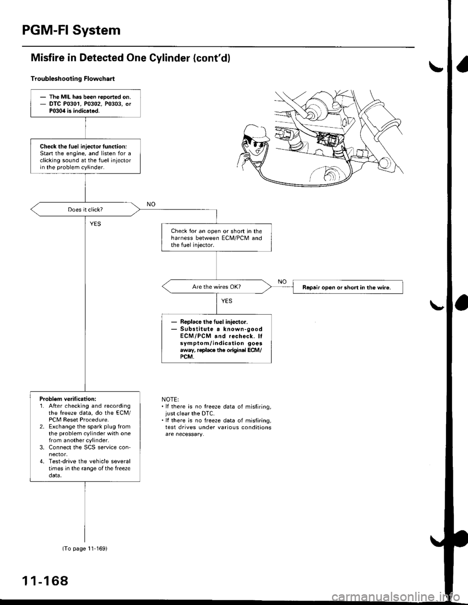
Misfire in Detected One Gylinder (cont'dl
Troubleshootin g Flowchart
NOTE:. lf there is no treeze data of misfiring,just clear the DTC.. It there is no freeze data of misfiring,test drives under various conditions
- The MIL has been reoorted on.- DTC P0301. P0302. P0303, orP030il is indicated.
Check the fuel iniecto. lunction:Stan the engine, and listen for aclicking sound at the fuel injectorin the problem cylinder.
Check for an open or short in theharness between ECM/PCM andthe fuel iniector.
Repair open or short in the wir€.
Replace the fuel iniector.Sub3titute a known-goodECM/PCM and recheck. Itsymptom/indication goesaway, replace the original ECM/PCM.
Problem verification:1. After checking and recordingthe freeze data, do the ECM/PCM Reset Procedure.2. Exchange the spark plug fromthe problem cylinder with onefrom another cylinder,3. Connect the SCS service con'nector,4. Test-drive the vehicle severaltimes in the range ofthe free2edata.
(To page 11-169)
1 1-1 68
Page 438 of 2189
I
ll
t
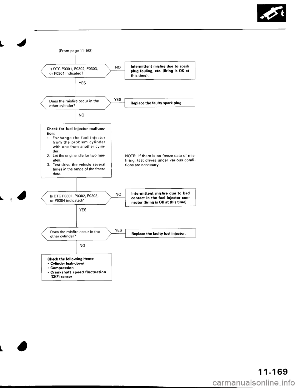
NOTE: lf there is no freeze data of mis_
firing, test drives under various condi
tions are necessary.
(From page 11'168)
Intermittent misfire due to sparkplug fouling, etc. (firing is OK arthis time).
ls DTC P0301, P0302, P0303,or P0304 indicated?
Does the misfire occur in theother cylinder?Replace the faulty spark plug.
Check for fuel iniector mallunc-
l|on:1. Exchange the fLrel injectorfrom the problem cylinderwith one from another cylinder.2. Let the engine idle for trrvo min-
utes.3. Test-drive the vehicle severaltimes in the range ot the freeze
data.
lntermitt€nt mistire due to badcontact in the fuel iniector con-nector (firing is OK at this time).
ls DTC P0301, P0302, P0303,or P0304 indicated?
Does the mistire occur in theother cylinder?Replace the taulty fuel injector.
Check lhe following items:. Cylinder leak-down. Compression. Crankshatt speod tluctuation
{CKF) sensoi
1 1-1 69
Page 441 of 2189
PGM-FI System
tFos3sl
tFffi6l
tPr361 I
fPfi62l
fFr38il
tF13s2-l
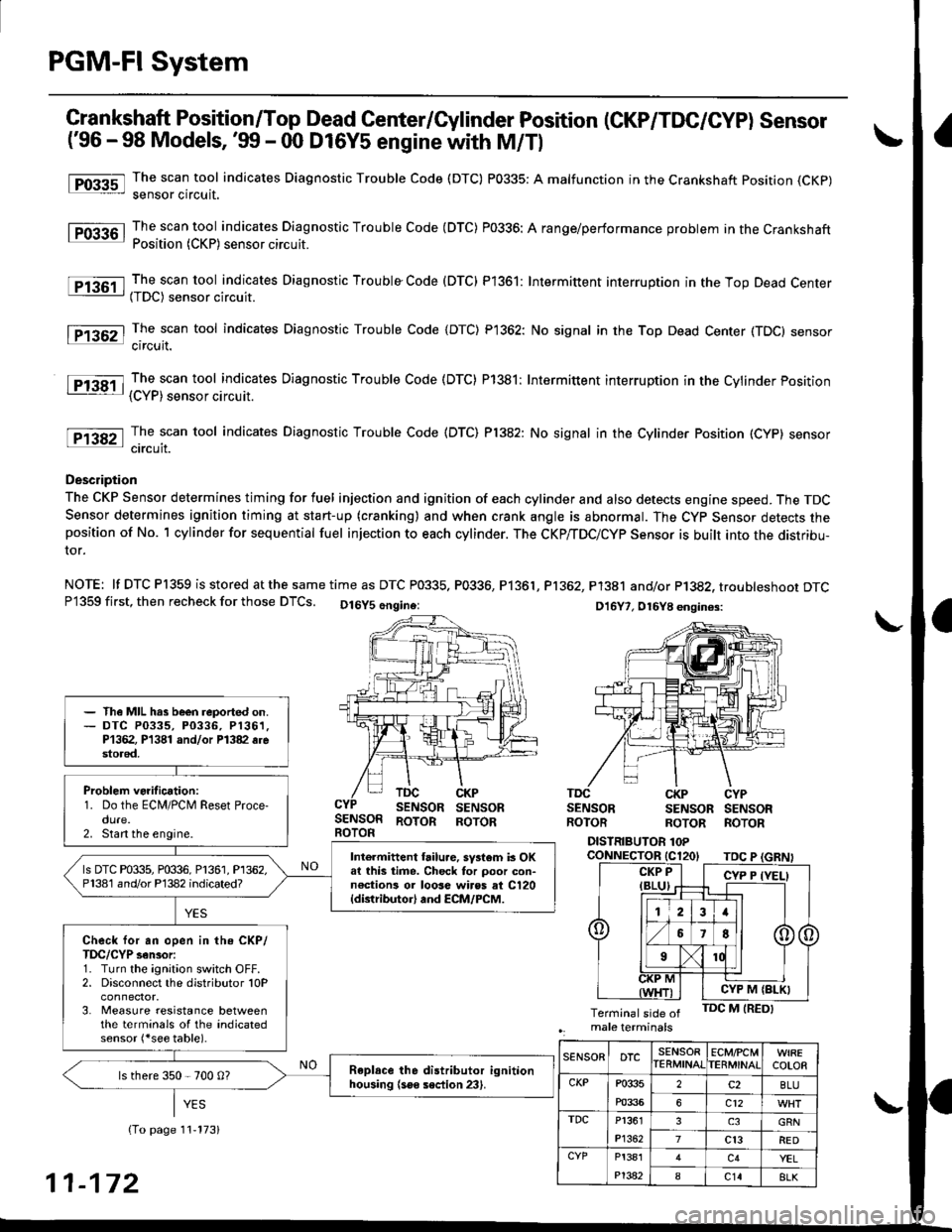
Crankshaft Position/Top Dead Genter/Gylinder Position (CKP/TDC/CYP) Sensor
('96 - 98 Models, '!n - 00 D16Y5 engine with M/Tl
The scan tool indicates Diagnostic Trouble Code (DTC) P0335: A malfunction in the Crankshaft position (CKp)
sensor circuit.
The scan tool indicates Diagnostic Trouble Code (DTC) P0336: A range/performance problem in the CrankshaftPosition (CKP) sensor circuit.
The scan tool indicates Diagnostic Trouble Code (DTC) P1361: Intermittent interruotion in the Too Dead Center(TDC) sensor circuit.
The scan tool indicates Diagnostic Trouble Code {DTC) P1362: No signal in the Top Dead Center (TDC} sensorcircuit.
The scan tool indicates Diagnostic Trouble Code (DTC) P1381: Intermittent interruption in the Cvlinder Position{CYP) sensor circuit.
The scan tool indicates Diagnostic Trouble Code {DTC) Pl382: No signal in the Cylinder Position (CYP} sensorcircuit.
Description
The CKP Sensor determines timing for fuel injection and ignition of each cylinder and also detects engine speed. The TDCSensor determines ignition timing at start-up (cranking) and when crank angle is abnormal. The Cyp Sensor detects theposition of No. 1 cylinder for sequential fuel injection to each cylinder. The CKP/TDC/CYP Sensor is built into the distribu-ror.
NOTE: lf DTC P1359 is stored atthesametime as DTC P0335. P0336, P1361, Pl362, P1381 and/or P1382, troubteshoor DTCP1359 first, then recheck for those DTCS. Ot6y5 6ngine: Dt6y7, ot6y8 enqin6s:
SENSORBOTOR
TDCSENSORCKPSENSORSENSORROTORSENSORROTORSENSORROTORROTORROTOR
DISTRIBUTOR 1OPcoNNECTOR tC120tTDC P
- The MIL hrs been reported on.- DTC P0335, P0336, P1361,P1362, P1381 and/or Pl382 6restored,
Problem verification:1. Do the ECM/PCM Reset Proce-dure.2. Stan the engine.
Intermittent hilu.e, system b OKat this time. Check tor poor con-n€ctions or 10036 wiros at C120{distributor} and ECM/PCM.
ls DTC P0335, P0336, P1361, P1362,P1381 and/or P'l382 indicated?
Check for an open in the CKP/TDC/CYP sensor:1. Turn the ignition switch OFF.2. Disconnect the distributor 10P
3. Measure resistance betweenthe terminals of the indicatedsensor (*see table).
Replace the distributor ignitionhousing (soe section 23).ls there 350 - 700 0?
CYP M {BLK}
SENSORDTCSENSORIERMINATECMfCMTERMINATCOLOR
CKPP033s
m336
2c2BLU
6c12
TDCP1361
P1362
3GRN
7cl3RED
CYPP!381
P't382
c4YEL
8c148LK11-172
Page 443 of 2189
PGM-FI System
l-Fos3sl
tFos36l
tF1361 l
Fr362-1
tF13sil
Crankshaft Position/Top Dead Center/Cylinder Position (CKP/TDC/CYPI Sensor
f99 - 00 Models except D16Y5 engine with M/T)
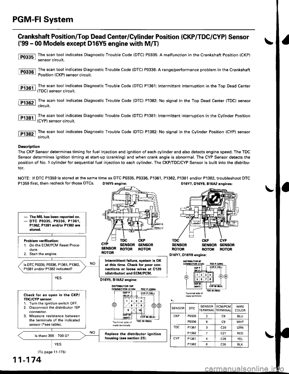
The scan tool indicates Diagnostic Trouble Code (DTC) P0335: A malfunction in the Crankshaft Position (CKP)
sensor circuit.
The scan tool indicates Diagnostic Trouble Code (DTC) P0336: A range/performance problem in the Crankshaft
Position (CKP) sensor circuit.
The scan tool indicates Diagnostic Trouble Code (DTC) P1361: Intermittent interruption in the Top Dead Center
{TDC) sensor circuit.
The scan tool indicates Diagnostic Trouble Code {DTC) P1362: No signal in the Top Dead Center (TDC) sensor
circuit.
The scan tool indicates Diagnostic Trouble Code (DTC) P1381: Intermittent interruption in the Cylinder Position(CYP) sensor circuit.
lTiaSt The scan tool indicates Diagnostic Trouble Code (DTC) P1382; No signal in the Cylinder Position (CYP) sensor: circuil.
DoscriDtion
The CKP Sensor determines timing for fuel injection and ignition of each cylinder and also detects engine speed. The TDC
Sensor determines ignition timing at start-up (cranking) and when crank angle is abnormal. The CYP Sensor detects the
position of No. 1 cylinder for sequential fuel injection to each cylinder. The CKP/TDC/CYP Sensor is built into the distribu-
tor.
NOTE; lf DTC P1359 is stored at the same time as DTC P0335, P0336, P1361. P1362, P1381 and/or P1382, troubleshoot DTC
P1359 first, then recheck for those DTCS. D16Y5 engino:
SENSORROTOR
TDGSENSORCKPSENSOBTDCSENSOBCKPSENSOBCYPs€NsonBOTORROTORBOTONROTOR ROTOR
D16Y7, D16Y8 ongine:
(To page 11-175)
1-174
- The MIL has been reportod on.- DTC P0335, P0336. P1361,P1362, P1381 rnd/or P1382.restored.
Problem verific{tion:1. Do the ECM/PCM Reset Proce-dure.2. Start the engine.
Intormittcnt failure, systom b OKat thb time. Check to. poor con-nections or loose wires at C120(dktributorl and ECM/PCM.
ls DTC P0335, P0336, P1361, P1362,P1381 and/or Pl382 indicated?
Check tor an open in the CKP/TDC/CYP 3enior:1. Turn the ignition switch OFF.2. Disconnect the distributor 10Pconnector,3. Measure resistance betweenthe terminals of the indicatedsensor (*see table).
Replrce the distributor ignitionhou3ing (!ee section 231.ls there 350 700 0?
SENSORDTCSENSORTEBMINAIECM/PCMTERI\,4INAICOLOR
CKPP0335
P0336
2c88LU
6c9
TDCP1361
P1362
3c20GRN
7c21BED
CYPP1381
P1342
c29YEL
Ic30BLK
Page 456 of 2189
l,a
Crankshaft Position/Top Dead Center/Cylinder Position (CKP/TDC/CYPI Sensor
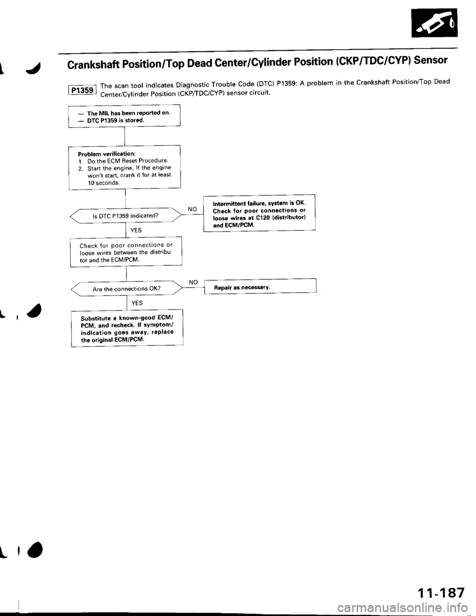
Thescantoo|indicatesDiagnosticTroub|ecode(DTc)P1359:Aprob|eminthecrankshaftPosjtion/TopDead
Center/Cvlinder Position (CKP/TDC/CYP) sensor circuit'
- The MIL has been reported on- DTC P1359 is stored
Problem veritication:1. Do the ECM Reset Procedure
2. Stan the engine lftheengine
won't start, crank it for at least
10 seconds-
lntermittent failure, sYstem is OK
Check for poor connecllon3 or
loose wires at C120 {distributor}and ECM,/PCM.
ls DTC P1359 indicated?
Check for poor connections or
loose wires between the distribu
tor and the ECM/PCM
Substitute a known'good ECM/
PCM, and rccheck. lt 3ymPtom/
indication goes awtY, rePlace
the original ECM/PCM.
r ta
11-1A7
Page 516 of 2189
IThrottle BodY
Description
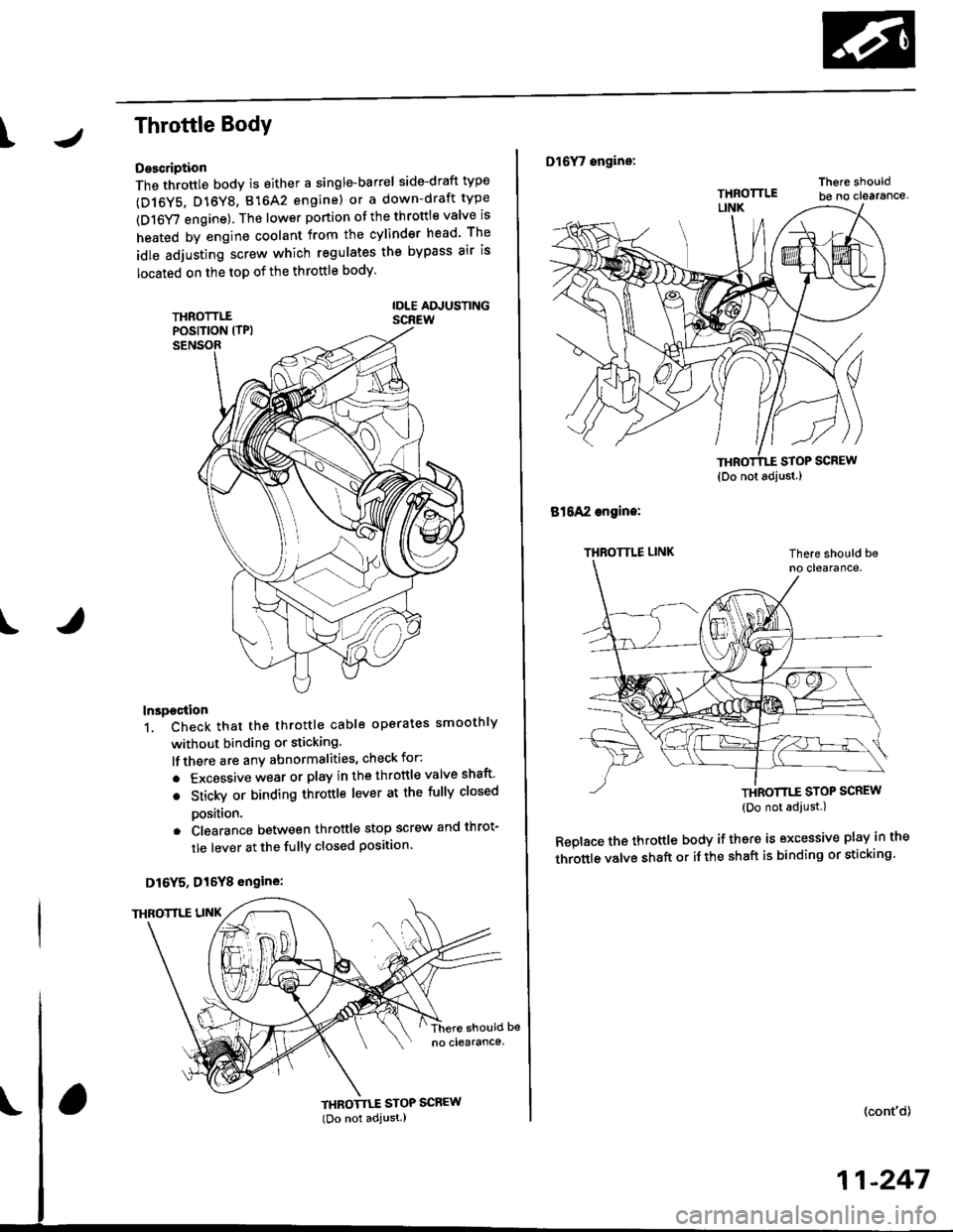
The throttle bodY is either a single-barrel side-draft type
(D16Y5, D16Y8, 816A2 engine) or a down-draft type
(D16Y/ engine). The lower portion ot the throttle valve is
heated by engine coolant from the cylinder head' The
idle adjusting screw which regulates the bypass air is
located on the top of the throttle body
THROTTLEPOS|T|ON lTPlSENSOR
IDLE AD.'USTINGSCREW
t
In3pection
1. Check that the throttle cable operates smoothly
without binding or sticking.
lf there are any abnormalities, check for:
. Excessive wear or play in the throttle valve shaft'
. StickY or binding throttle lever at the fully closed
Position.. Clearance between throttle stop screw and throt-
tle lever at the fully closed position'
D16Y5, Dl6Y8 engine:
THROTTLE STOP SCREW
{Do not adjust.)
Dl6Y7 ongine:
816A2 engins:
THROTTLE LINK
STOP SCREW
THROTTTE STOP SCREW(Do not adjust.)
Replace the throftle body if thsre is excessive play in the
throttle valve shaft or iJ the shaft is binding or sticking'
(cont'd)
11-247
{Do not adjust.)
Page 568 of 2189
J
t
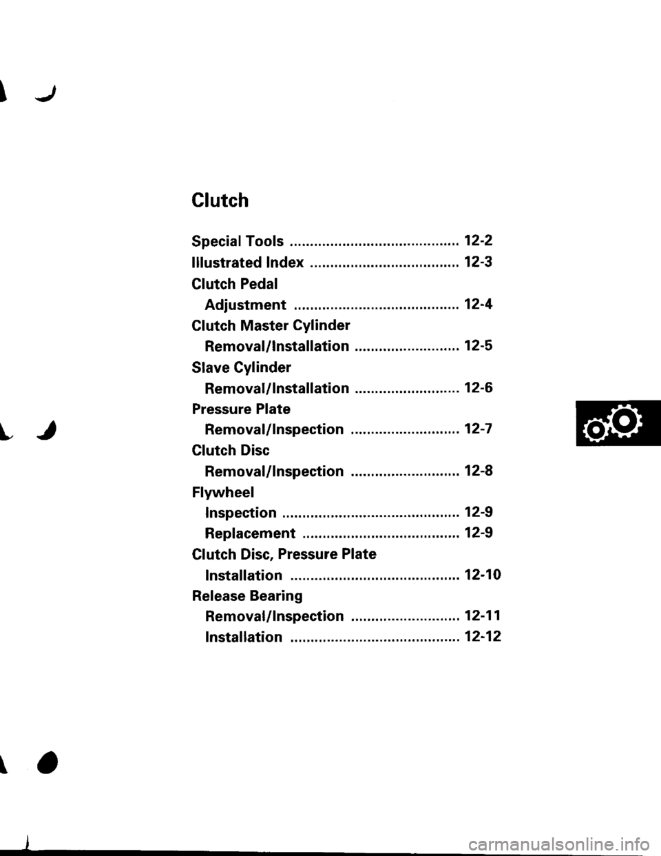
Clutch
Speciaf Tools .......... ...........12-2
f lfustrated Index .......... ......12-3
clutch Pedal
Adjustment .................... 12'4
Clutch Master Cylinder
Removal/lnstallation ..... 12-5
Slave Cylinder
Removal/lnstallation .....12'6
Pressure Plate
Removal/lnspection ...... 12-7
Clutch Disc
Removal/lnspection ...... 12-8
Flywheel
Inspection ....................... 12-9
Replacement ....................................... 12-9
Clutch Disc, Pressure Plate
lnstallation ..................... 12-10
Release Bearing
Removal/lnspection ......12-11
f nstalfation .................,... 12-12
\
Page 570 of 2189
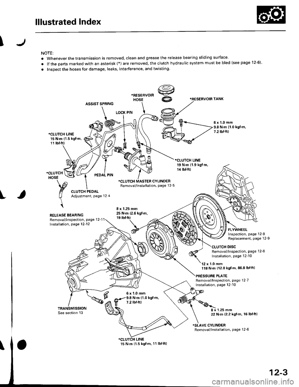
lllustrated Index
\
NOTE:
. Whenever the transmission is removed, clean and grease the release bearing sliding surface
. lf the parts marked with an asterisk (*) are removed, the clutch hydraulic system mustbe bled (seepage 12-6)
. Inspect the hoses for damage, leaks, interference, and twisting
'RESERVOIF TANK
ASSIST SPRING
LOCK PIN
5x1,0mm9.8 N.m (1.0 kgf.m,7.2 tbtftl*CLUTCH LINE15 N.m {1.5 kgJ m,11 tbt.ft)
RELEASE BEARINGRemoval/lnspection, page 12-1 1Installation, page 12-'12
*CLUTCH MASTER CYLINDERRemoval/lnstallation, page 12 5
6x1.0mm9.8 N.m (1.0 kgf.m,7.2 tbf.ft)
FLYWHEELInspectaon, page 12IReplacement, Page 12-9
CLUTCH DISCRemoval/lnspection, page 1 2-8
lnstallation, page 12-'10
'12 x 1.0 mm118 N.m {12.0 kgt'm,86.8lbfft)
PBESSURE PLATEBemoval/lnspection, page 12 7Installation, page 12''10
8 x 1.25 mm22 N m (2.2 kgf.m, 16lbf ft)
ISLAVE CYLINDERRemoval/lnstallation, page 12_6
12-3
Page 571 of 2189
Glutch Pedal
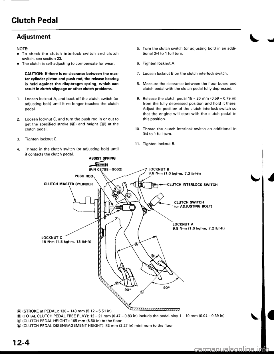
Adjustment
NOTE:
. To check the clutch interlock switch and clutch
switch, see section 23.
. The clutch is self-adjusting to compensate for wear.
CAUTION: lf there is no clearance between the mas-
ter cylinder pislon and push rod, the release bearing
is held against the diaphragm spring, which can
result in clutch slippage 01 other clutch problems.
1. Loosen locknut A, and back off the clutch switch (or
adjusting bolt) until it no longer touches the clutch
peoar.
2. Loosen locknut C, and turn the push rod in or out to
get the specified stroke {@} and height (@) at tne
clutch pedal.
3. Tighten locknut C.
4. Thread in the clutch switch {or adiusting bolt) until
it contacts the clutch pedal.
9002)
Turn the clutch switch (or adjusting bolt) in an addi-
tional 3/4 to 1 full turn.
Tighten locknut A.
Loosen locknut B on the clutch interlock switch.
Measure the clearance between the floor board and
clutch pedal with the clutch pedal fully depressed.
Release the clutch pedal 15 - 20 mm {0.59 - 0.79 in)
from the fully depressed position and hold it there.
Adjust the position of the clutch interlock switch so
that the engine will start with the clutch pedal in
this position.
Thread the clutch interlock switch an additional in
3/4 to 1 full turn.
Tighten locknut B.
LOCKNUT B9.8 N.m (1.0 k91.m,7.2 lbt.tt)
INTERLOCK SWITCI{
J
'lL
5.
7.
8.
9.
10.
ASSIST SPRING
-Atl
CLUTCH SWITCH
lo. ADJUSTING BOLTI
LOCKNUT A9.8 N'm (1.0 kgI.m, 7.2 lbf,ft)
LOCKNUT C18 N.m {1.8 kql.m, 13lbf.ft}
@ (STROKE at PEDAL): 130 - 140 mm (5.12 - 5.51 in)
@ (TOTAL CLUTCH PEDAL FREE PTAYI: 12 - 21 mm (0.47 - 0.83 in) includethepedal play 1 10 mm (0.04 - 0.39 in)
@ (CLUTCH PEDAL HEIGHT): '�]65 mm {6.50 in) to the floor
@ (CLUTCH PEDAL DISENGAGEMENT HEIGHT): 83 mm (3.27 in) minimum to the floor
12-4