Mount HONDA CIVIC 1998 6.G Workshop Manual
[x] Cancel search | Manufacturer: HONDA, Model Year: 1998, Model line: CIVIC, Model: HONDA CIVIC 1998 6.GPages: 2189, PDF Size: 69.39 MB
Page 1609 of 2189
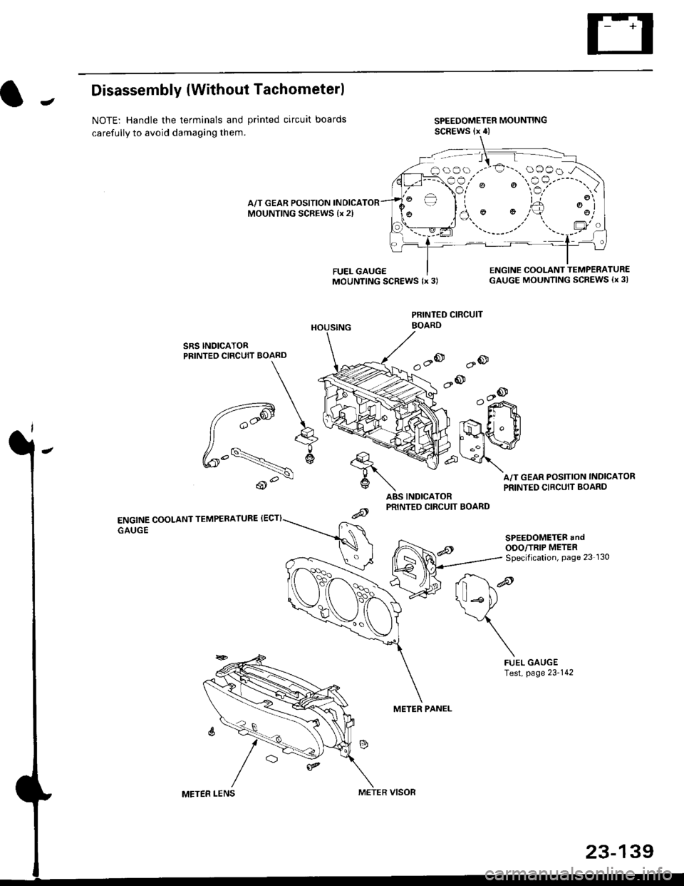
JDisassembly {Without Tachometerl
NOTE: Handle the terminals and printed circuit boards
carefully to avoid damaging them.
SPEEDOMETER MOUNTINGSCREWS (x 4)
A/T GEAR POSITION INDICAMOUNTING SCREWS {x 2l
SRS INOICATORPRINTED CIRCUIT BOARD
ENGINE COOLANT TEMPERATURE {ECT}
GAUGE
ABS INDICATORPRINTED CIRCUIT BOARD
PRINTED CIRCUIT
METER PANEL
FUEL GAUGEMOUNTING SCREWS {x 3)ENGINE COOLANT TEMPERATUR€GAUGE MOUNTING SCREWS {x 3l
A/T GEAR POSITION INDICATOR
PRINTED CIRCUIT BOARD
'a@
.-@--o
o"i^>
Er t
lmwp\
d*re
\*P
\
FUELTest,GAUGEpage 23-142
oOo ,.-'€'-., oOOo -/\
€3,'" ' "$?'----"')
)a.' '.,,'+ ':j
\ll Lto
BOARD
METER LENSMETER VISOR
23-139
Page 1625 of 2189
A/T Gear Position Switch
Replacement
1.
2.
7.
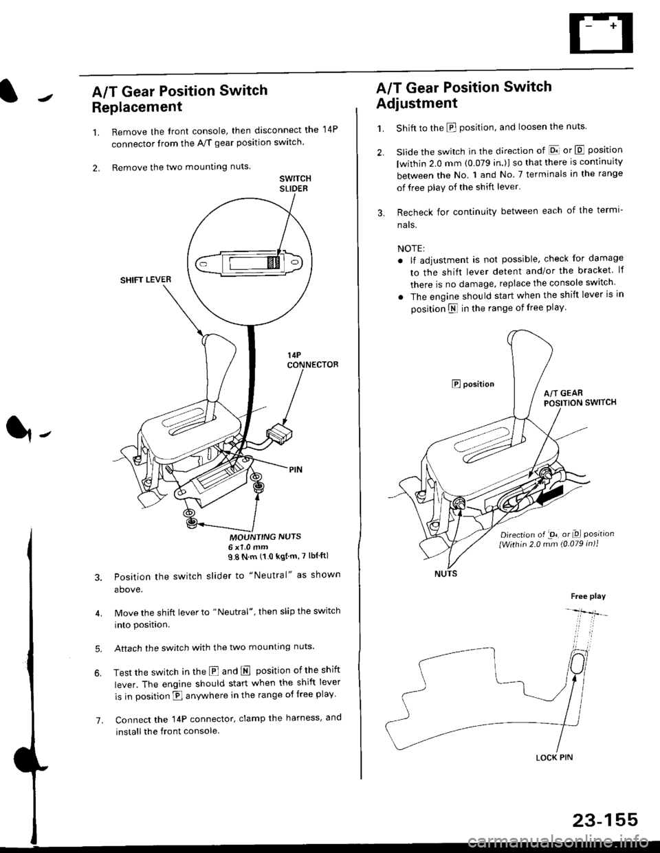
Remove the front console, then disconnect the
connector from the A/f gear position swltch
Remove the two mounting nuts
swrTcHSLIDEB
MOUNT'NG NUTS6x1 0mm98Nm(10kgtm'7lblftl
Position the switch slider to "Neutral" as shown
above.
Move the shift lever to "Neutral", then slip the switch
into position.
Aftach the swjtch with the two mounting nuts.
Test the switch in the E and E position ofthe shift
lever. The engine should start when the shift lever
is in position fl anywhere in the range of free play
Connect the 14P connector, clamp the harness, and
install the front console
14P
A/T Gear Position Switch
Adjustment
1.
3.
Shift to the E position, and loosen the nuts.
slide the switch in the direction of El or E position
lwithin 2.0 mm (0.079 in.)l so that there is continuity
between the No. 1 and No 7 terminals in the range
of free play of the shift lever'
Recheck for continuity between each of the termi-
nats.
NOTE:
. lf adjustment is not possible, check for damage
to the shift lever detent and/or the bracket lf
there is no damage. replace the console switch
. The engine should start when the shift lever is in
position N in the range of free play
E positionA/T GEARPOSITION SWITCH
Djrection of -on, or Dl Positionlwithin 2.0 mm (0.079 in)1
Free play
-lfr-
LOCK PIN
23-155
Page 1631 of 2189
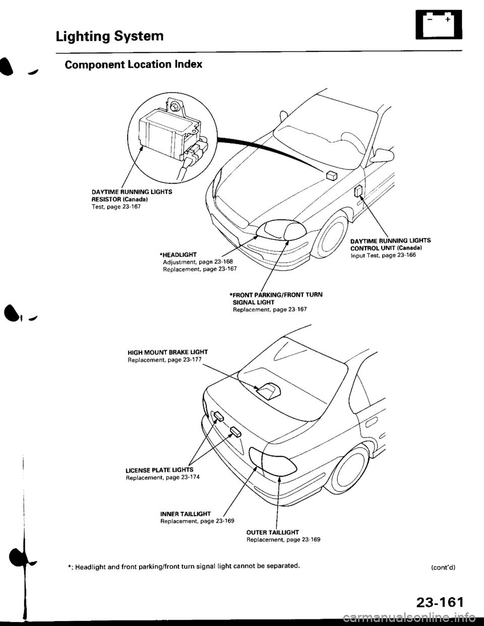
Lighting System
Component Location Index
DAYTIME RUNNING LIGHTSRESISTOR {Canada)Test, page 23 167
DAYTIME RUNNING LIGHTS
CONTROL UNIT (Canadal
Input Test, Page 23 166*HEADLIGHT
Adiustment, page 23-168Replacement, page 23-167
SIGNAL LIGHTReplacement, page 23 167
HIGH MOUNT BRAKE LIGHT
Replacement, page 23-177
LICENSE PLATE LIGHTS
Replacement, Page 23'174
INNER TAILLIGHTReplacement, page 23-169
OUTER TAILLIGHTReplacement, page 23 I69
*: Headlight and front parking/front turn signal light cannot be separated.(cont'd)
23-161
Page 1637 of 2189
Headlights/Front Turn
Signal/Parking Lights
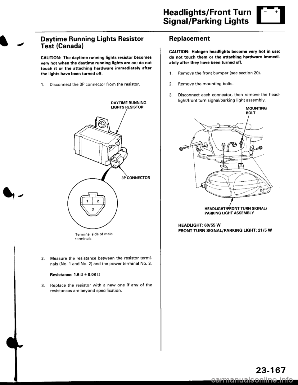
Daytime Running Lights Resistor
Test (Canada)
CAUTION: The daytime running lights resistor becomes
very hot when the daytime running lights are on; do not
touch il or the attaching hardware immediately after
the lights have been iurned off.
1. Disconnect the 3P connector from the resistor.
Terminal side of male
terminals
N4easure the resistance between the resistor termi
nals (No. 1 and No. 2) and the power terminal No. 3.
Resistance: 1.6 O t 0.08 O
Replace the resistor with a new one if any of the
resistances are beyond specification.
It-
Replacement
CAUTION: Halogen headlights b€come very hot in use;
do not touch them or the attaching hardware immedi-
ately after they have been turned off.
1. Remove the front bumper (see section 20).
2. Remove the mounting bolts,
3. Disconnect each connector, then remove the head-
lighVfront turn signal/parking light assembly.
MOUNTINGEOLT
HEADLIGHT/FRONT TUFN SIGNAL/PARKING LIGHT ASSEMBLY
HEADLIGHT: 60/55 W
FRONT TURN SIGNAL/PARKING LIGHT: 21l5 w
23-167
Page 1641 of 2189
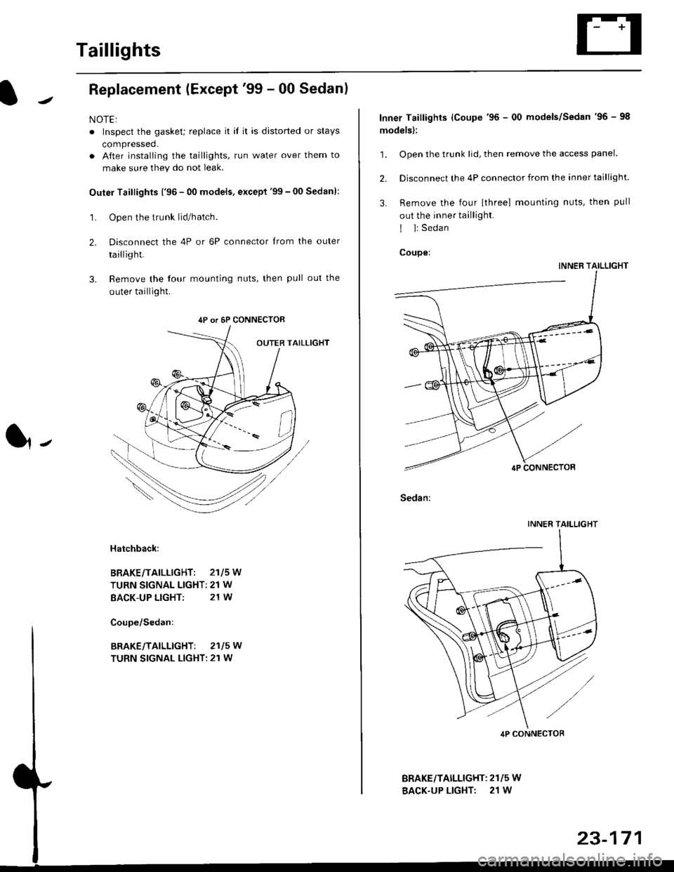
Taillights
Replacement (Except'99 - 00 Sedanl
NOTE:
. Inspect the gasket; replace it il it is distorted or stays
compressed.
. After installing the taillights, run water over them to
make sure they do not leak.
Outer Taillights ('96 - 00 models, except'99 - 00 Sedan):
1. Open the trunk lid/hatch.
2. Disconnect the 4P or 6P connector trom the outer
taillight.
3. Remove the four mounting nuts, then pull out the
outer taillight.
l-
Hatchback:
BRAKE/TAILLIGHT: 2115W
TURN SIGNAL LIGHT: 21 W
BACK-UP LIGHT: 21 W
4P or 6P CONNECTOR
BRAKE/TAILLIGHT: 2115W
TURN SIGNAL LIGHT: 21 W
BRAKEiTAILLIGHT: 2115 W
BACK-UP LIGHT: 21 W
Inner Taillights (Coupe'96 - 00 models/Sedan'96 - 98
models):
1. Open the trunk lid, then remove the access panel.
2. Disconnect the 4P connector from the inner taillight.
3. Remove the four [three] mounting nuts, then pull
out the inner taillight.
I l: Sedan
Coupei
INNER TAILLIGHT
Sedan:
INNER TAILLIGHT
4P CONNECTOB
Page 1642 of 2189
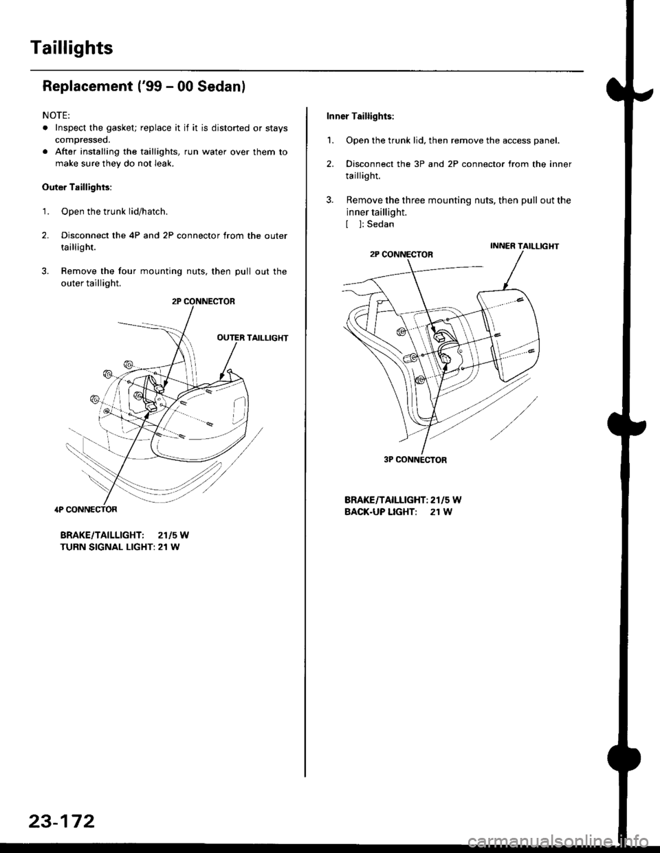
Taillights
Replacement ('99 - 00 Sedanl
NOTE:
. Inspect the gasket; replace it if it is distorted or stays
compressed.
. After installing the taillights, run water over them to
make sure they do not leak.
Outer Taillights:
1. Open the trunk lid/hatch.
2. Disconnect the 4P and 2P connector trom the outer
taillight.
3. Remove the four mounting nuts, then pull out the
outer taillight.
TAILLIG}fi
4P CONNECTOR
BRAKE/TAILLIGHT: 2115W
TURN SIGNAL LIGHT: 21 W
r*i/et./
23-172
Inner Taillights:
'1. Open the trunk lid, then remove the access panel.
2. Disconnect the 3P and 2P connector from the inner
taillight.
3. Remove the three mounting nuts, then pull out the
inner taillight.
[ ]: Sedan
BRAKE/TAILLIGHT: 2r15 W
BACK.UP LIGHT: 21 W
3P CONNECTOR
Page 1649 of 2189
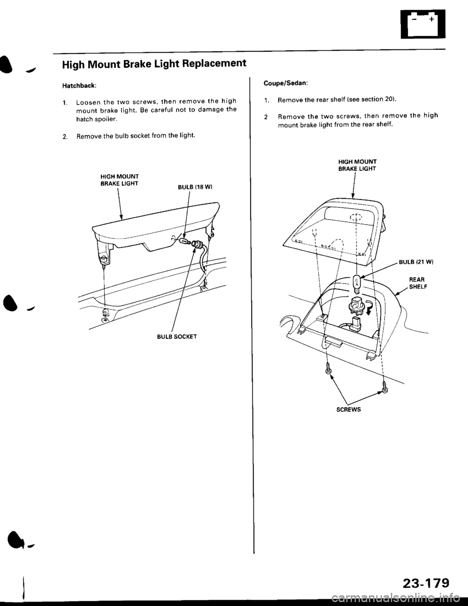
High Mount Brake Light Replacement
Hatchback:
1. Loosen the two screws, then remove the high
mount brake light. Be careful not to damage the
hatch spoiler.
2. Remove the bulb socket from the light.
BULB SOCKET
l-
23-179
Coupe/sedan:
1. Remove the rear shelf (see section 20).
2 Remove the two screws, then remove the high
mount brake light from the rear shelf.
HIGH MOUNTBRAKE LIGHT
SCREWS
Page 1655 of 2189
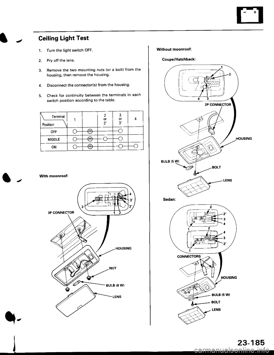
Ceiling Light Test
1. Turn the light switch OFF
2. Pry off the lens.
3. Remove the two mounting nuts (or a bolt) from the
housing, then remove the housing.
4. Disconnect the connector{s) from the housing.
5. Check for continuity between the terminals in each
switch position according to the table.
With moonroof:
3P CONNECTOR
rermrnal
Position \
12or2'
3or3'�
OFFo-/a\-o\7
MIDDLEo-,.\--o\:/
ONo---o\:/
23-185
q,
Without moonroot:
Coupe/Hatchback:
BULB (5 WI
/
2'
4
1
3
Page 1661 of 2189
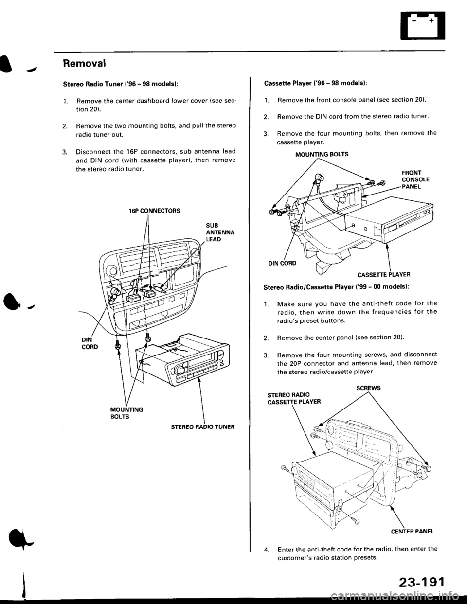
Removal
Stereo Radio Tuner ('96 - 98 modelsl:
3.
1.
2.
Remove the center dashboard lower cover (see sec-
tion 20).
Remove the two mounting bolts, and pullthe stereo
radao tuner out.
Disconnect the 16P connectors, sub antenna lead
and DIN cord (with cassette playerl, then remove
the stereo radio tuner.
16P CONNECTORS
1.
2.
Cassette Player ('96 - 98 modelsl:
Remove the front console panel (see section 20).
Remove the DIN cord from the stereo radio tuner.
Remove the four mounting bolts, then remove the
cassette player.
Stereo Radio/Cassette Player ('99 - 00 modelsl:
1. Make sure you have the anti-theft code for the
radio, then write down the frequencies for the
radio's oreset buttons.
Remove the center panel (see section 20).
Remove the four mounting screws, and disconnect
the 20P connector and antenna lead, then remove
the stereo radio/cassette player.
2.
3.
MOUNTING BOLTS
scREws
Enter the anti-theft code for the radio, then enter the
customer's radio station Presets.
23-191
Page 1665 of 2189
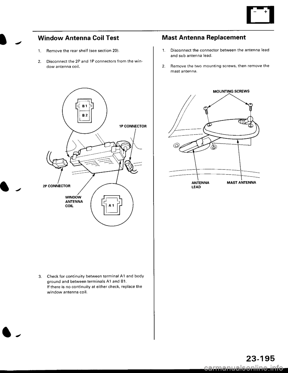
Window Antenna Coil Test
2.
1.
wtNoowANTENNAcotL
Remove the rear shelf (see section 20).
Disconnect the 2P and lP connectors from the win-
dow antenna coil.
1P CONNECTOB
2P
-l
CONNECTOR
3.Check for continuity between terminal A1 and body
ground and between terminals 41 and 81.
lf there is no continuity at either check, replace the
window antenna coil.
lq 81 1l
tf--llLB2lllL-,--rl
23-195
Mast Antenna Replacement
1.
2.
Disconnect the connector between the antenna lead
and sub antenna lead.
Remove the two mounting screws, then remove the
mast antenna.
MAST ANTENNA
MOUNTING SCREWS