heater switch HONDA CIVIC 1998 6.G User Guide
[x] Cancel search | Manufacturer: HONDA, Model Year: 1998, Model line: CIVIC, Model: HONDA CIVIC 1998 6.GPages: 2189, PDF Size: 69.39 MB
Page 428 of 2189
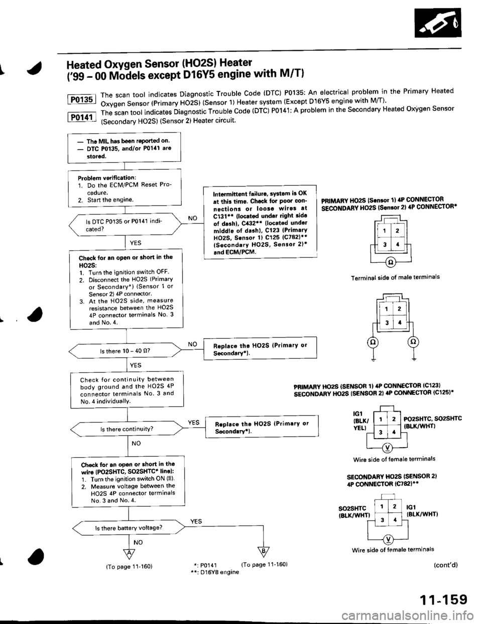
IHeated Oxygen Sensor (HO2S) Heater
i'ss - oo Mb-dels except D16Y5 engine with M/Tl
The scan toot indicates Diagnostic Trouble Code (DTC) P0135: An electrical problem in the Primary Heated
Oxygen Sensor (Primary ttOiS) (Sensor 1) Heater system {Except D15Y5 engine with M/T)'
The
-scan tool indicates Diagnostic Trouble Code (DTC) P0141; A problem in the Secondary Heated Oigen Sensor
(Secondarv HO2S) {Sensor 2) Heater circuit
Fo13sl
Fol11l
lntermiftent failuro, sYstom b OK
at thit limo. Ch6ck lor Poor oon'
nectiont or looso wita! at
C131'* {loc.tod und.t right ido
ol drshl, C432'* (located undel
middlo of dashl, C123 (PrimarY
HOzS, Sensor 1) C125 (Ct82lr'
(socondary HO2S, Sensor 2)t
.nd ECM/PCM.
PRIMAFY HO2S ls.n.or ll rrP CONNECTOR
SECOITIDARY HO2S (Srn.ol21 4P CONNECTOR'
Terminal side of male terminals
PRIMARY HO2S {SENSOR 1} ilP @NI{ECTOR lc123l
sEcoNDARY HO2S ISENSOR 2) aP @NNECTOR (C125)'
3l-, l-tl-t Fo2sHrc. so2sHrc
ver.t l ^-1 .'l {BLK/wHrl
11 '!'l-l
| --=- Iu----{v)'---..-'
Wire side of {emale terminals
SECO'TIDARY Ho2S (SENSOR 2,
4P CONNESTOR {C7&llt'
so2sHTc(BLKnflHTlIBLK/WHT)
(cont'd)
1 1-159
Wire side oI female terminals
r: p0141 {To page 11-160}**: D16Yg engine
- The MIL has been reponed on.- DTC P0135. and/or P0141 are
storod.
Problem vorification:1. Do the ECM/PCM Reset Pro-
cedute.2. Stan the englne.
Chock foi an open or short in the
HO25:1. Turn the ignition switch OFF
2. Disconnect the HO2S (Primary
or Secondary*) lSensor 1 or
Sensor 2) 4P connector'
3. At the H02S side, measure
resistance between the HO2S
4P connector terminals No. 3
and No.4.
ls there 10 - 40 n?
Check for continuity between
body ground and the HO2S 4P
connector terminals No. 3 and
No.4 individuallY.
Check for an opon or short in lho
wire (PO2SHTC, SO2SHTC+ line):'1. Turn the ignition switch ON (ll).
2. Measure voltage between the
H02S 4P connector termlnalsNo.3 and No.4.
{To page 11-160}
Page 429 of 2189
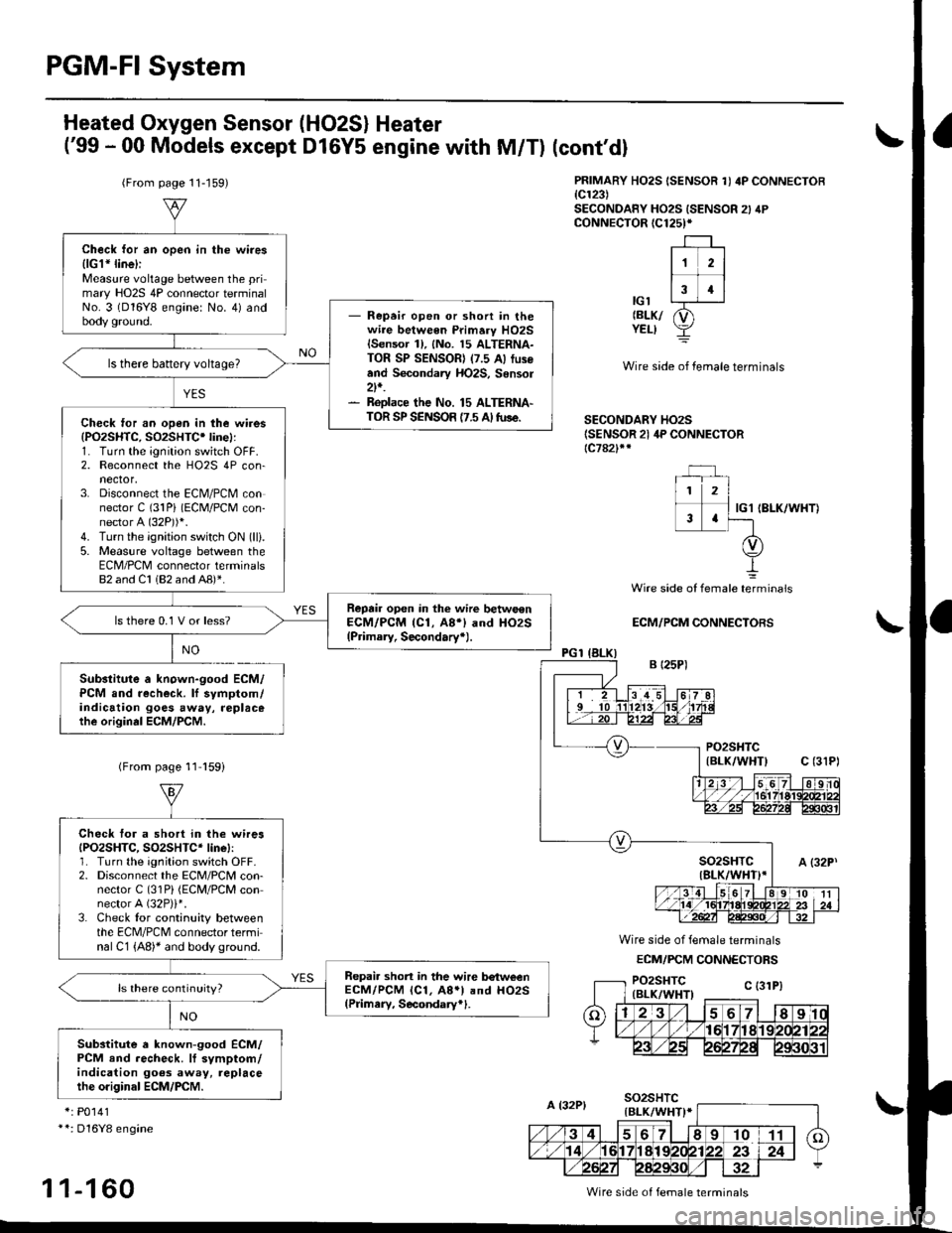
PGM-FI System
Heated Oxygen Sensor (HO2S) Heater
('99 - 00 Models except D16Y5 engine with M/T)
(From page 11-159)
Substitute a known-good ECM/PCM and recheck. lf symptom/indication goes away, replacethe origin.l ECM/PCM.
(cont'dl
PRIMARY HO2S ISENSOR 1I 4P CONNECTOB{c123)SECONDANY HO2S ISENSOR 2} 4PcoNNECTOR (C125)*
-r--r ,
lr zl
-f-13 4llc'l L--r-J-r
relxr p1YELI Y
Wire side of temale terminals
SECONDARY HO2S(SENSOR 21 4P CONNECTOR{c782}rr
IG1 IBLK/WHT)
NO
Wire side of female telminals
ECM/PCM CONNECTORS
Wire side of female terminals
ECM/FCM CONNECTORS
*: P0141**: Dl6Y8 engine
1 1-1 60
Check for an open in the wires{lGl* line}iMeasure voltage between the primary HO2S 4P connector terminalNo. 3 (D16Y8 engine: No. 4) andbody ground.- Repeir open or shon in thewire between Primary HO2Slsensor 1), {No. 15 ALTERNA-TOR SP SENSOR) (7.5 A) fus€and Secondary HO2S, Sensor2t,.- ReDlace the No. 15 ALTERNA-TOR SP SENSOR {7.5 A tuse.
ls there battery voltage?
Check ,or an open in the wires(PO2SHTC, SO2SHTC' linel:1. Turn the ignition switch OFF.2. Reconnect the HO2S 4P con-nector,3. Disconnect the ECN4/PCM connector C (31Pi (ECM/PCM con-nector A (32P))i.
4. Turn the ignition switch ON (lli.
5. Measure voltage between theECM/PCM connector terminals82 and Cl 182 and AB)*.
Reprir open in the wirc betwo€nECM/PCM (Cl, A8i) and HO2S(Primary, Secondary+).
ls there 0.1 V or less?
(From page 11 l59i
Check tor a short in the wiresIPO2SHTC, SO2SHTC* linel:1. Turn the ignition switch OFF.2. Disconnect the ECM/PCM con-nector C (31Pi (ECM/PCM connector A (32P)i*.
3. Check tor continuity betweenthe ECM/PCM connector terminal C1 {A8)* and body ground.
Repai. short in the wire b€tweenECM/PCM lcl, A8.l and HO2S(Pdmery, Secondary*1.
Substitute a known-good ECM/PCM end recheck. lf symptom/indication goes away, replacethe o.iginal ECM/PCM.
Wire side of female terminals
Page 430 of 2189
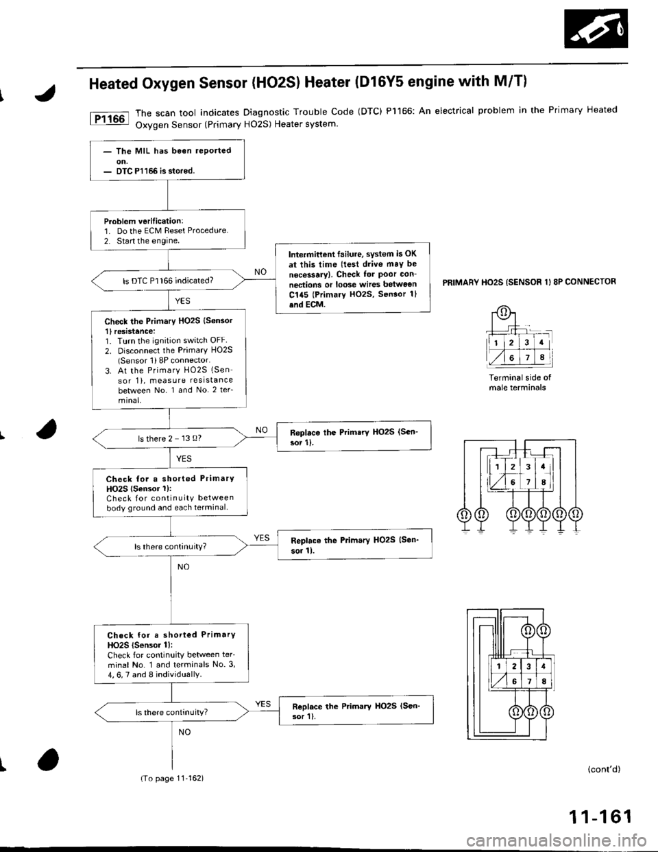
Heated Oxygen Sensor (HO2SI Heater (Dl6Y5 engine with M/Tl
The scan tool indicates Diagnostic Trouble Code (DTC) P1166: An electrical problem in the Primary Heated
Oxygen Sensor (Primary H02S) Heater system.
PRIMABY HO2S ISENSOR 1I 8P CONNECTOR
Terminal side ofmale terminals
I(cont'd)
11-161
- The MIL has been lePorted
- DTC Pl166 b stored.
Problem verilication:1. Do the ECM Reset Procedure.
2. Start the engine.
Intermitlent failura, sYstem b OK
at this time (te3t drive maY be
ngcessary). Check for poor con-
nections or loose wires between
C145 (Primary HO2S, Sen3or 1l
end ECM.
ls DTC P'l166 indicated?
Check the Primary HO2S (Sensot
1l resistence:1. Turn the ignition switch OFF
2. Disconnect the Primary HO2S(Sensor 1) 8P connector.
3. At the Primary HO2S (Sen
sor 1), measure resistance
between No. 1 and No. 2 ter_
Replace lhe Primery HO2S (Sen-
sor 11.ls there 2 13 O?
Check for a shorted PrimarY
HO2S lsensor 1):Check for continuity between
body ground and each terminal.
Check for a shorted PrimarY
HO2S {S€nsor 1l:
Check for continuity between ter'
minal No. 1 and terminals No.3,
4, 6, 7 and 8 individually.
ls there conlrnuily?
(To page 11'162)
Page 431 of 2189
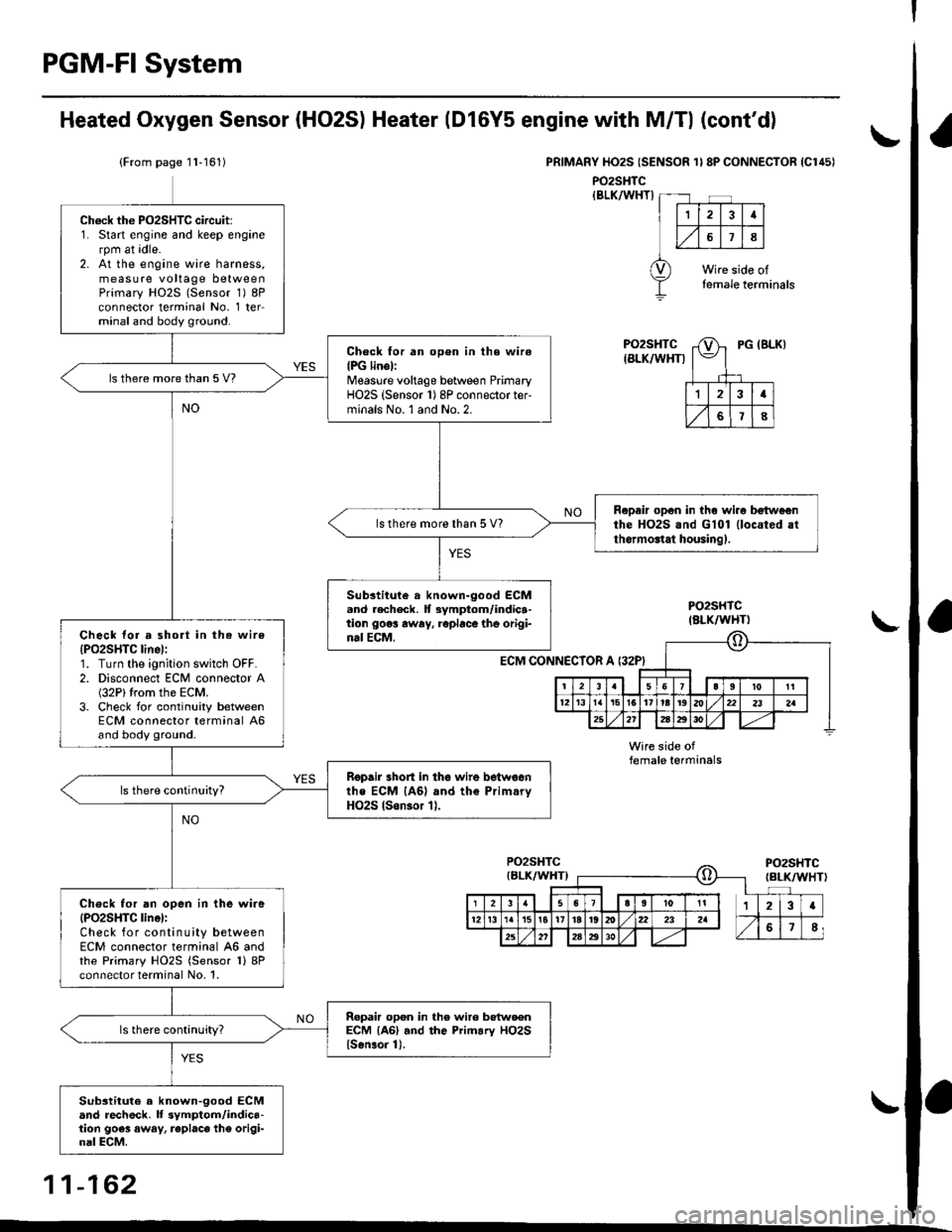
PGM-FI System
I
a
a
Ch6ck the PO2SHTC circuit:1. Start engine and keep enginerpm at idle.2. At the engine wire harness,measure voltage betweenPrimary HO2S (Sensor 1) 8Pconnector terminal No. 1 terminal and body ground.
Check for an open in the wire(PG linellMeasurc voltage between PrimaryHO2S (Sensor 1) 8P connector ter-minals No. l and No.2.
ls there morethan 5 V?
Repair opon in the wi.o bEtwoonthe HO2S.nd G101 (located atth.rmonat housingl.
ls there more than 5 V?
Substitule a known-good ECM.nd .echeck. lt 3ymptom/indica-tion 906! rwry, roplace the origi-nal ECM,Check lor a short in the wire
{PO2SHTC line):1. Turn the ignition switch OFF.2. Disconnect ECM connector A(32P)trom the ECM.3. Check for continuity betweenECM connector terminal 46and body ground.
Ropair 3hort in tho wire betwoenthe ECM {46} and the Prim.ryHO2S lson3or 11.
Check for an open in the wire(PO2SHTC linel:Check for continuity betweenECM connector terminal 46 andthe Primary HO2S (Sensor 1)8Pconnector terminal No. 1.
Repair opsn in the wir6 botweenECM {A6} .nd the Primary HO2Slsonror 1).
Substituto a known-9ood ECMand rech6ck. lf symptom/indica-tion goes away, replace the origi-nal ECM.
Heated Oxygen Sensor (HO2S) Heater (Dl6Y5 engine with M/Tl (cont'd)
(From page 11-161)PRIMARY HO2S (SENSOR 1} 8P CONNECTOR {Cl45I
PO2SHTC{BtK/WHT)
PO2SHTCIALK/WHTI
ECM CONNECTOR
female terminals
11-162
\.
!
\
A {32P}
o
6I9l roIt
12t3l5t61't8t9a221 232a
252'2aEito,1| ---
Page 432 of 2189
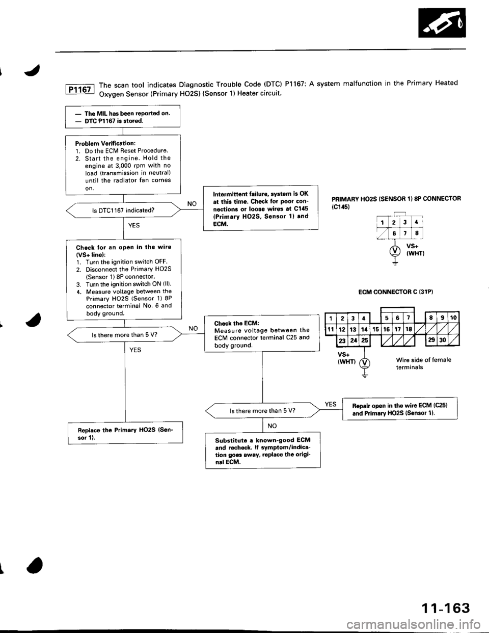
The scan tool indicates Diagnostic Trouble Code (DTC) Pl167: A system malfunction in the Primary Heated
Orygen Sensor {Primary HO2S) (Sensor 1) Heater circuit
PRIMABY HO2S ISENSOR 1} 8P CONNECTOR
tc145l
ECM CONNECTOR C (31P)
- The MIL has be€n reported on.- DTC Pl167 i3 3tored.
Problem Veritication:1. Do the ECM Reset Procedure.
2. Start the engine. Hold the
engine at 3,000 mm with no
load (transmission in neutral)
until the radiator fan comes
on.Intormittont failure, system i3 OK
at thia time. Chock for Poor con_
noction3 or looso wilgt ai Cl45(Primary HO2S, Son3or 1l andECM.
ls DTC1167 indicated?
Check lor sn open in the wire(VS+ linel:1. Turn the ignition switch OFF
2. Disconnect the Primary HO2S
{Sensor 1) 8P connector.
3. Turn the ignition switch ON (ll).
4. Measure voltage betwe€n thePrimary HO2S (Sensor '1) 8P
connector terminal No 6 and
body ground.
Ch.ck the ECM:Measure voltage between the
ECM connector terminsl C25 and
body ground.
ls there more than 5 V?
Repair opon in the wite ECM (C25)
and P m.ry HO2S (S€n3or 11.ls there more than 5 V?
Replaco the Primary HO2S (Son-
sor 11.Substitute ! known-good ECM
and r6check. lf symptom/indica-tion gos6 away, r.place tho origi'
nd ECM,
,l23458910
111213t415161718
a2125a30
VS+{WHTIWire side of femaleterminals
1 1-163
Page 489 of 2189
ldle Control System
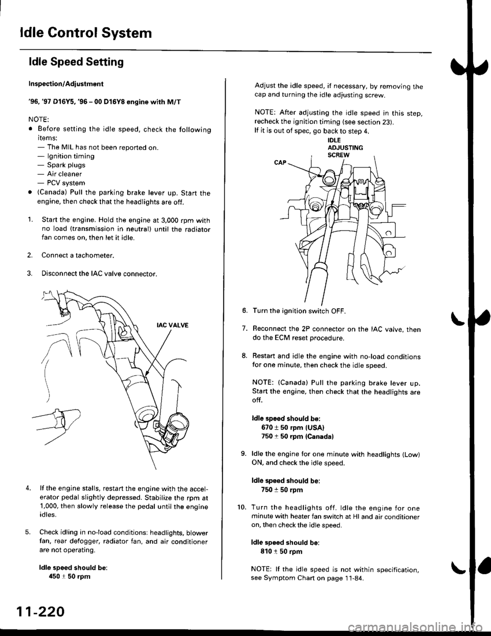
ldle Speed Setting
Inspection/Adiustmenl
'96, '97 Dl6Y5. '96 - 00 Dl5Y8 sngine with M/T
NOTE:
. Before setting the idle speed, check the following
items:- The MIL has not been reported on.- lgnition timing- Spark plugs- Air cleaner- PCV system
o (Canada) Pull the parking brake lever up. Start the
engine, then check that the headlights are off.
1. Start the engine. Hold the engine at 3.000 rpm withno load (taansmission in neutral) until the radiatorfan comes on, then let it idle.
2. Connect a tachometer.
3. Disconnect the IAC valve connector.
4.lf the engine stalls, restart the engine with the accel-
erator pedal slightly depressed. Stabilize the rpm at1,000, then slowly release the pedal until the engineidles.
Check idling in no-load conditionsr headlights. blowerfan. rear defogger, radiator fan, and air conditioner
are not operating.
ldle spsed should be:
450 1 50 rpm
11-220
Adjust the idle speed, if necessary, by removing thecap and turning the idle adjusting screw.
NOTE; After adjusting the idle speed in this step,recheck the ignition timing (see section 23).
lf it is out of spec, go back to step 4.
IDLE
6. Turn the ignition switch OFF.
7. Reconnect the 2P connector on the IAC valve, then
do the ECM reset procedure.
8. Restart and idle the engine with no-load conditionsfor one minute, then check the idle speed.
NOTE: (Canada) Pull the parking brake lever up.Start the engine, then check that the headlights areoff.
ldle sp€sd should b€:
670 i 50 rpm IUSA)750 t 50 rpm {Canada}
9. ldle the engine tor one minute with headlights {Low)ON. and check the idle speed.
ldle speed should be:
750 :r 50 rpm
10. Turn the headlights off. ldle the engine for oneminute with heater fan switch at Hl and air conditioneron, then check the idle speed.
ldle speed should be:
810150 rpm
NOTE: lf the idle speed is not within specification,see Symptom Chan on page 11-84.
Page 490 of 2189
t
t
I
'96.'97 D16Y5 engine with CVT,'96 - 00 D16Y8 ongins
with A/T and'96 - 00 Dl6Y7 €ngine
Adiust the idle speed using a Honda PGM Tester if pos-
sible. lf not, use the following procedure:
NOTEI
. Leave the IAC valve connected
. Betore setting the idle speed. check the following
items:- The MIL has not been reported on'
- lgnition timing
- Spark Plugs- Air cleaner- PCV system
1. Connect a tachometer.
2. Start the engine. Hold the engine at 3,000 rpm wirh
no load (in Park or neutral) until the radiator fan
comes on, then let it idle.
3. Check the idle speed with no-load conditions: head-
iights, blower fan, rear defogger, radiator fan, and
air conditioner are not operatlng
ldl€ spoed should be:
USA:
D16Y5 engine with CVT, D16Y7 engine with A/T'
Dl6YB engine with A/T:
700 :r 50 rpm (in E or El Positionl
D16Y7 engine with M/T:
670 i 50 rpm
Canada:
Dl6Y8 sngin€, Dl6Y7 engins:
M/T750 t 50 rpm
NT750 1 50 rpm (in E or El Position)
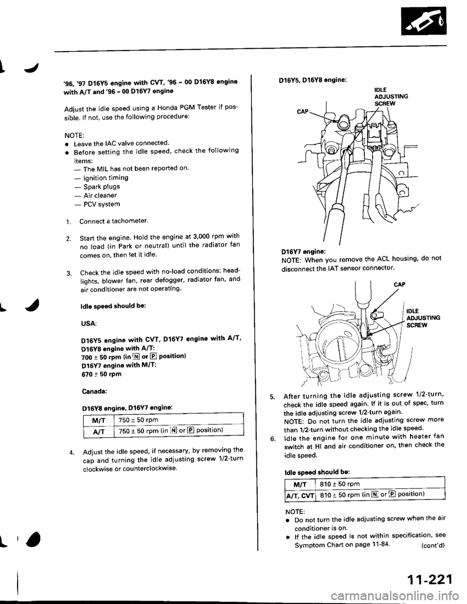
Adjust the idle speed, if necessary, by removing the
cap and turning the idle adiusting screw 1/2-turn
clockwise or counterclockwise
D16Y5, D16Y8 engine:
IDLEADJUSTING
Dl6f, ongine:
NOTE: When you remove the ACL housing, do not
disconnect the IAT sensor connector
After turning the idle adjusting scrow 1/2-turn'
check the idle speed again. lf it is out of spec, turn
the idle adjusting screw 1/2-turn agaan'
NOTE: Do not turn the idle adjusting screw more
than 1/2-turn without checking the idle speed'
ldle the engine for one minute with heater fan
switch at Hl and air conditioner on, then check the
idle speed.
ldle speed should be:
M/T810150 rpm
A/T. CvT810 t 50 rpm (in El or E Position)
NOTE:
. Do not turn the idle adjusting screw when the air
conditioner is on.
. lf the idle speed is not within specification. see
Symptom Chart on page 11-84 (cont'd)
11-221
Page 491 of 2189
ldle Control System
ldle Speed Setting (cont'dl
Inspeqtion/Adiustment
38 D16Y5 engine whh M/T,'99 - 00 81642 engine
NOTE: Before setting the idle speed, check the follow-ing items;- The MIL has not been reported on.- lgnition timing- Spark plugs- Air cleaner- PCV system
'1. Start the engine. Hold the engine at 3,000 rpm withno load (transmission in neutral) until the radiatorfan comes on, then let it idle.
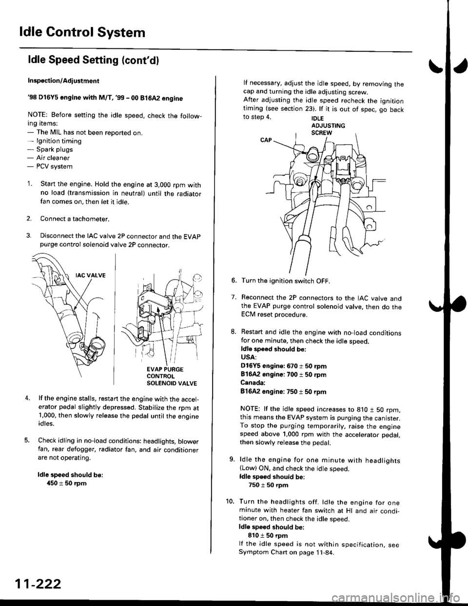
Connect a tachometer.
Disconnect the IAC valve 2P connector and the EVAPpurge controlsolenoid valve 2P connector.
EVAP PURGECONTROLSOLENOID VALVE
lf the engine stalls, restart the engine with the accel-erator pedal slightly depressed. Stabilize the rpm at1.000, then slowly release the pedal until the engineidles.
Check idling in no-load conditions: headlights, blowerfan, rear defogger, radiator fan, and air conditionerare not operating.
ldl€ speed should be:
450 i 50 rpm
11-222
lf necessary, adjust the idle speed, by removrng lnecap and turning the idle adjusting screw.After adjusting the idle speed recheck the ignitlontiming (see section 23). lf it is out of spec, go backto step 4. |DLE
6. Turn the ignition switch OFF.
7. Reconnect the 2P connectors to the IAC valve andthe EVAP purge control solenoid valve, then do theECM reset procedure.
8. Restart and idle the engine with no-load conditionsfor one minute, then check the idle sDeed.ldle speed should bo:
USA:
D16Y5 engine: 670 i 50 rpm
81642 engine: 700 i 50 rpm
Canada:
81642 engine: 750 t 50 rpm
NOTE: lf the idle speed increases to 8lO t 50 rpm,this means the EVAP system is purging the canister.To stop the purging temporarily, raise the enginespeed above 1,000 rpm with the accelerator pedal,
then slowly release the pedal.
9. ldle the engine for one minute with headlights(Low) ON. and check the idle speed.
ldle speed should be:
750 i 50 rpm
10. Turn the headlights off. ldle the engine for oneminute with heater fan switch at Hl and air condi-tioner on, then check the idle soeed.ldls speed should be:
810 t 50 rpm
lf the idle speed is not within specification, seeSymptom Chart on page 11-84.
Page 492 of 2189
\
I
'98 - 0O D16Y5 ongine with CvT
Adjust the idle speed using a Honda PGM Tester if pos-
sible. lf not, use the following procedure:
NOTE:
. Leave the IAC valve connected.
. Before s€tting the idle speed, check the following
rtems:- The MIL has not been reported on.
- lgnition timing
- Spark Plugs- Air clean€r
- PCV svstem
'1. Connect a tachometer.
2. Stan the engine. Hold the engine at 3,000 rpm w'th
no load (transmission in E or E] position) until the
radiator Jan comes on, then let it idle.
3. Check the idle speed under no-load conditions:
head lights, blower fan, rear defogger, radiator fan,
and air conditioner are not operatlng.
ldlo spaod ehould bo: 700 t 50 rpm
. lf the idle speed is within the specification, the
procedure is comPlete.
. lf the idle sDeed is out of specitication, 9o to step 4'
4. tf the idle speed is 810 1 50 rpm, this means the
EVAP system is purging the canister. To stop the
purging temporarily, raise the engine speed above
l,OO0 rgm with the accelsrator pedal. Slowly release
the pedal. and rscheck the idl€ speed.
. tf the idle speed is within the specificstion, the
Drocedure is comPlete.
. lf the idle sp€ed is out of spocification, go to step 5.
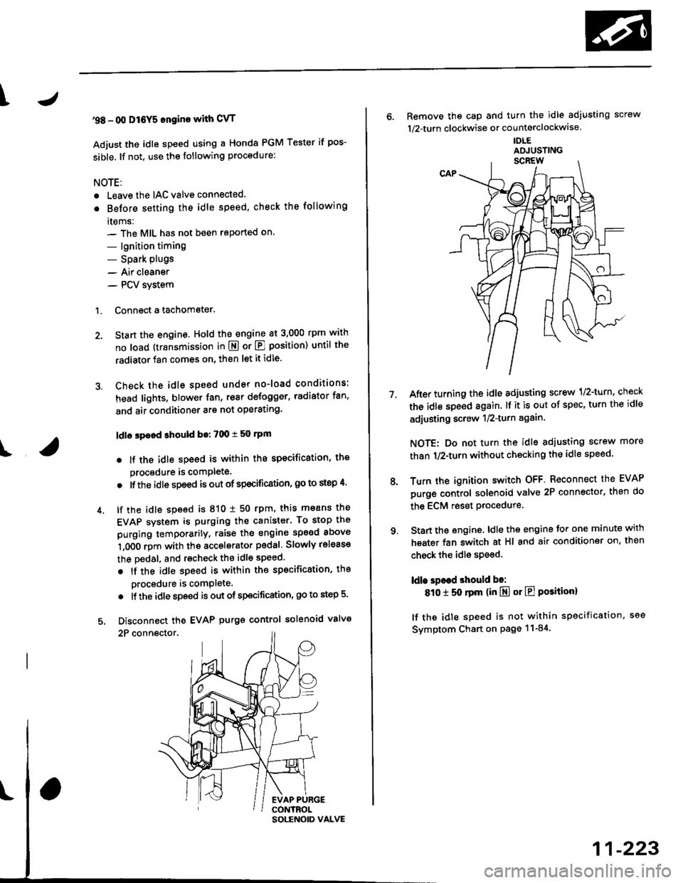
5. Disconnect th€ EVAP purgs control solenoid valve
2P connector.
EVAP PURGECONTROL
6. Remove the cap and turn the idle adiusting screw
1/2-turn clockwise or counterclockwlse
IDLE
7.After turning the idle adjusting screw 1/2-turn, check
the idl€ speed again. lf it is out of spec, turn the idle
adjusting screw 1/2-turn again.
NOTE: Do not turn the idle adjusting screw more
than 1/2-turn without checking the idle speed.
Turn the ignition switch OFF. Reconnect the EVAP
purge control solenoid valve 2P connector' then do
the ECM reset Procedure.
Start the engine. ldle the engine for one minute with
heater fan switch at Hl and air conditioner on, then
check the idle speed.
ldle spaed should be:
810 t 50 rpm (in El or E Posiiion)
lf the idle speed is not within specification, see
Svmptom Chart on Page 11-84.
9.
SOLENOID VALVE
11-223
Page 970 of 2189
Start Clutch Control@
T
Start Clutch Calibration Procedure
NOTE: When the following parts are replaced, the TCM
must memorize the feedback signal for the start clutch
control.
. TCM
. Transmissionassembly
. Stan clutch assembly
. Lower valve bodv assembly
. Engine assembly or overhaul
'96 Model Only
CAUTION: Do not uso this procsdure on'97 - (X) mod-
els or you will damage the transmission. On '97 - 00
models, the TCM or PCM memorizes ths loodback sig'
nals when you drive the vehicle.
1. Engage the parking brake, and block the front
wheels securely.
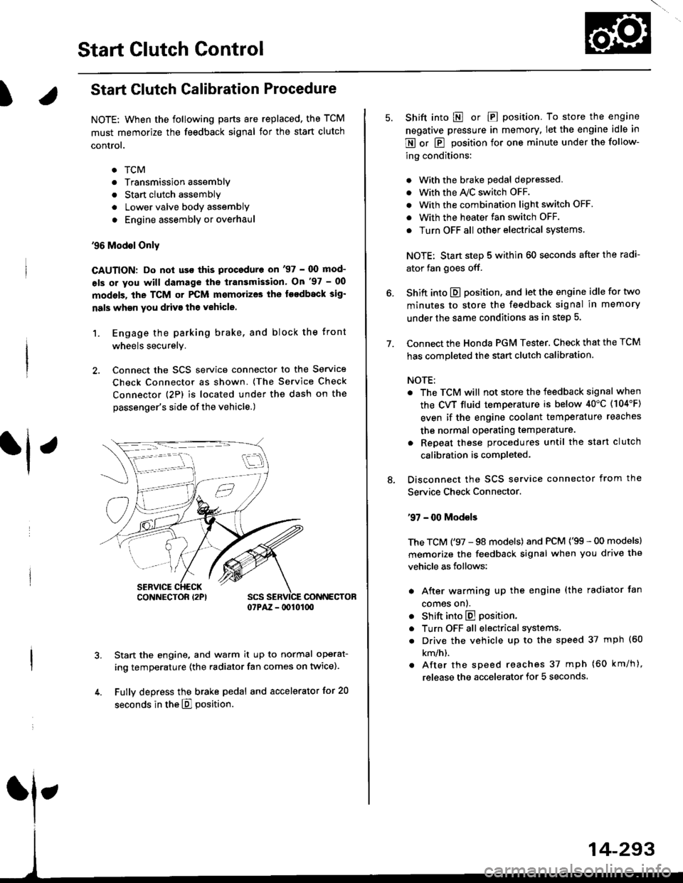
2. Connect the SCS service connector to the Service
Check Connector as shown. (The Service Check
connector (2P) is located under the dash on the
passenger's side of the vehicle.)
CONNECTOR07PAZ - lDl01(xt
Start the engine, and warm it up to normal operat-
ing temperature (the radiator fan comes on twice).
Fully depress the brake pedal and accelerator for 20
seconds in the E] position.
rl ,
CONNECTOR I2PI
14-293
7.
Shift into E o|. E position. To store the engine
negative pressure in memory. Iet the engine idle in
E or E position for one minute under the follow-
ing conditions:
. With the brake pedal depressed,
. with the y'\/c switch oFF.
. With the combination light switch OFF.
. With the heater fan switch OFF.
. Turn OFF all other electrical systems
NOTE: Start step 5 within 60 seconds after the radi-
ator fan goes off.
Shift into E position, and let the engine idle for two
minutes to store the feedback signal in memory
under the same conditions as in step 5.
Connect the Honda PGM Tester. Check that the TCM
has completed the start clutch calibration.
NOTE:
. The TCM will not store the feedback signal when
the CVT fluid temperature is below 40"C (104'F)
even if the engine coolant temperature reaches
the normal operating temperature.
. Repeat these procedures until the start clutch
calibration is completed-
Disconnect the SCS service connector from the
Service Check Connector.
'97 - 00 Models
The TCM ('97 - 98 models) and PCM ('99 - 00 models)
memorize the feedback signal when you drive the
vehicle as follows:
. After warming up the engine (the radiator fan
comes onl.
. Shift into E position.
. Turn OFF all electrical systems,
. Drive the vehicle up to the speed 37 mph (60
km/h).
. After the speed reaches 37 mph (60 km/h),
release the accelerator for 5 seconds.