heater switch HONDA CIVIC 1998 6.G Repair Manual
[x] Cancel search | Manufacturer: HONDA, Model Year: 1998, Model line: CIVIC, Model: HONDA CIVIC 1998 6.GPages: 2189, PDF Size: 69.39 MB
Page 1822 of 2189
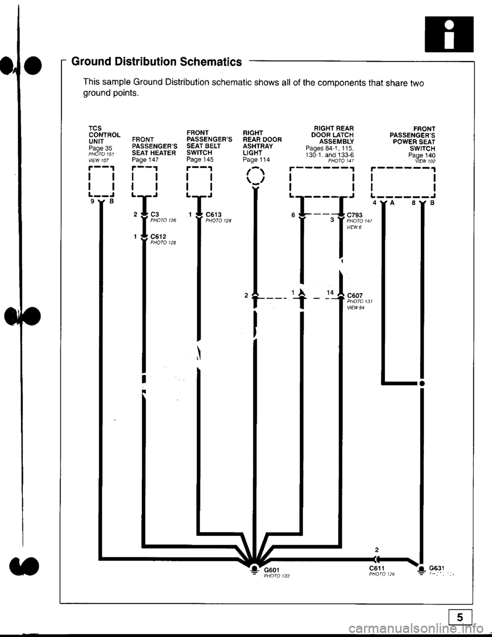
Ground Distribution Schematics
This sample Ground Distribution schematic shows all of the components that share two
ground points.
TCSCONTROLUNITPage 35
tl
tl
9Y B
FRONTPASSENGER'SSEAT HEATERPage 147
tl
FRONTPASSENGER'SSEAT BELTSWITCHPage 145
tl
ll
RIGHTREAR DOORASHTRAYLIGHTPage 114
r
\u
tl'T-'
29 3
l'::'"'^I - Ut
Z
II
I
G601c611
Page 1835 of 2189
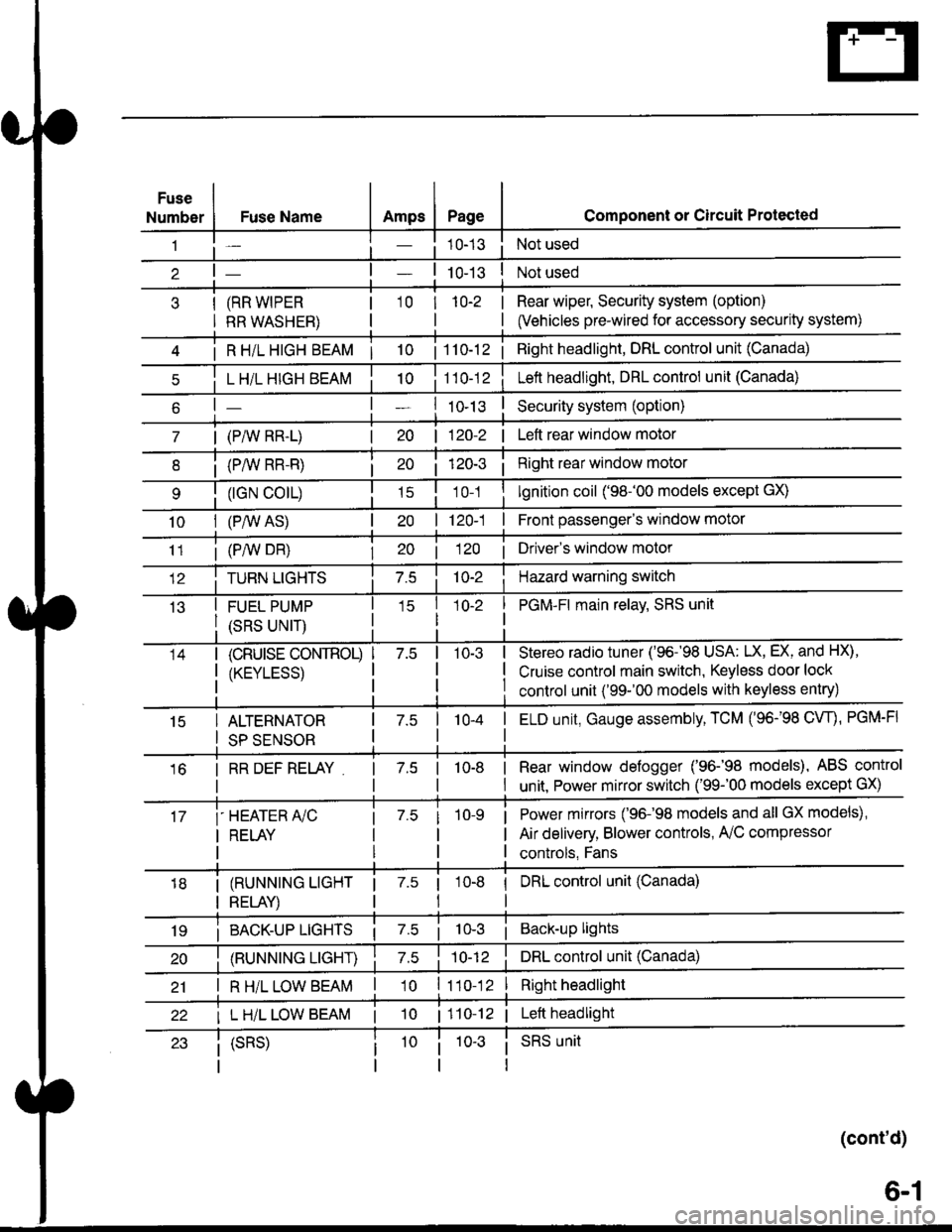
Fuse
NumberAmpsPageFuse Name
(RR WIPER
RR WASHER)
i R HiL HIGH BEAM | 10
L H/L HIGH BEAM
| (PAIV RR-L)
i (P/vv RR-R)
(rGN CO|L)
10I (P,^/V AS)
Component or Circuit Protected
Not used
Not used
Rear wiper, Security system (option)
(Vehicles pre-wired for accessory security system)
'10r 1n-2
I
| 1 10-12i Right headlight, DRL control unit (Canada)
Lett headlight, DRL control unit (Canada)
I ro-rsSecurity system (option)
| 120-2 | Left rear window motor
Right rear window motor
lgnition coil ('98-'00 models except GX)
| 120-1 | Front passenger's window motor
i (PiW DH)| 20 1 12O I Driver's window motor
TURN LIGHTSHazard warning switch
FUEL PUMP
(SRS UNIT)
PGM-FI main relav, SRS unit
(cRUrsE CoNTROL)
/KtrVt trSS\
Stereo radio tuner ('96-'98 USA: LX, EX, and HX),
Cruise control main switch, Keyless door lock
control unit ('99-'00 models with keyless entry)
15ALTERNATOR
SP SENSOR
l-a10-4I ELD unit, Gauge assembly, TCM (96-'98 CW, PGM-FI
16I RR DEF RELAY7.510-8I Rear window defogger ('96-'98 models), ABS control
I unit. Power mirror switch ('99-'00 models except GX)
i-HEATER r/C
I RELAY
Power mirrors ('96-98 models and all GX models),
Air delivery, Blower controls, AilC compressor
controls, Fans
I (RUNNING LIGHT
I RELAY)
1 7.5 1
tl
I DRL control unit (Canada)
i BACK-UP LTGHTSi Back-up lights
(RUNNING LIGHT)DRL control unit (Canada)
I R H/L LOW BEAM'10 l11o-12Right headlight
I L H/L LOW BEAM | 101110-12 | Left headlight
(cont'd)
(SRS)SRS unit
6-1
Page 1839 of 2189
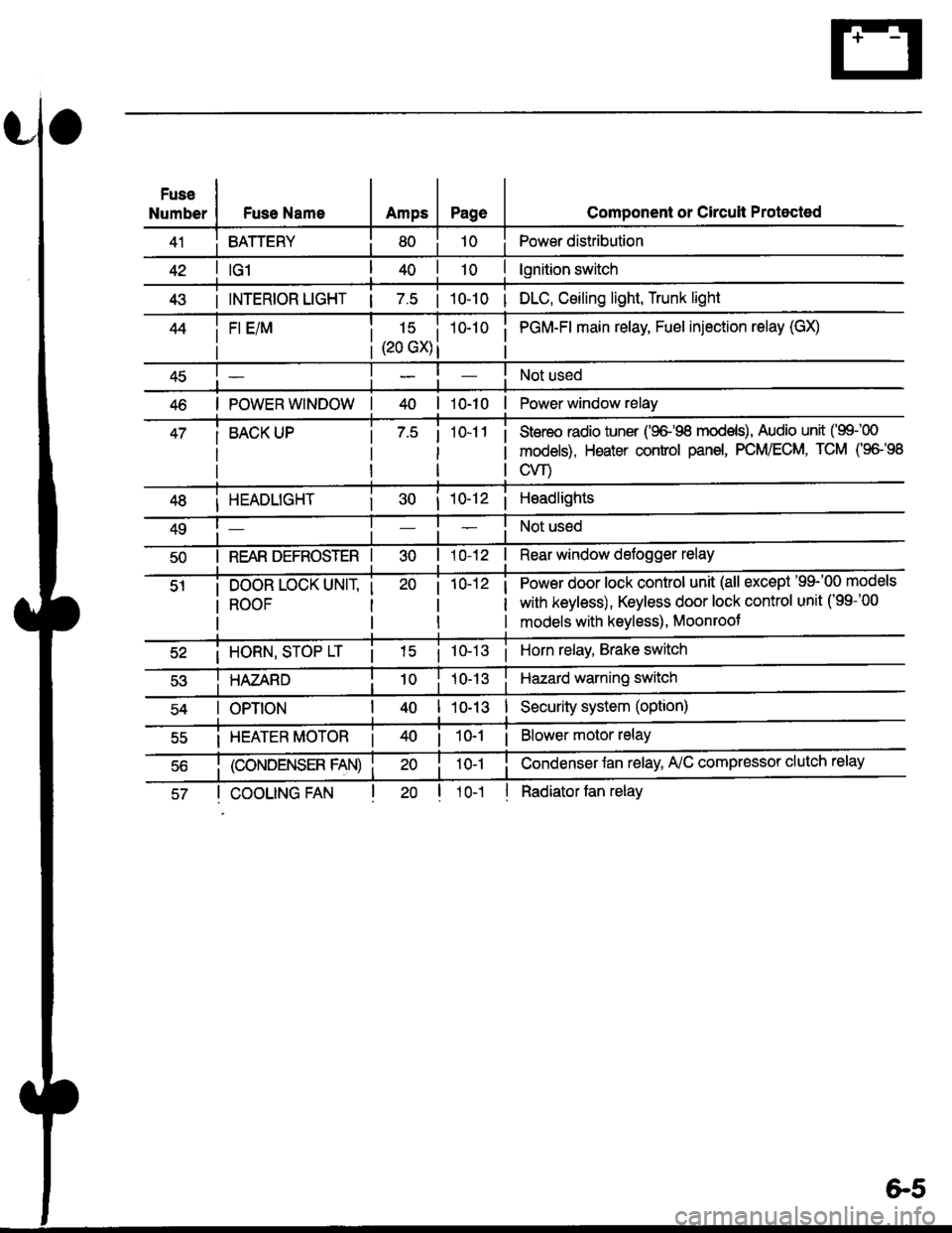
Fuse
NumberFuse NameAmpsPage
BATTERY
Component or Circult Protected
Power distribution
lgnition switch
INTERIOR LIGHT | 7.5 | 10-10 | DLC, Ceiling light, Trunk light
FI E/M15 i(20 GX) i
i PGM-FI main relay, Fuel injection relay (GX)
Not used
POWER WINDOW| 10-10 | Power window relay
BACK UPStereo radio iuner ('9G'98 mod€ls), Audio unit ('99100
models), Heater control panel, PCM/ECM, TCM (9e'98
cvr)
HEADLIGHT
REAR DEFROSTER I
DOOR LOCK UNIT,
ROOF
i 10-12i Headlights
Not used
Rear window defogger relay
Power door lock control unit (all except '99-'00 models
with keyless), Keyless door lock control unit ('99-'00
models with keyless), Moonroof
i HORN, SrOP Lri 10-13i Horn relay, Brake switch
HAZARDHazard warning switch
OPTIONI 10-13I Security system (option)
i HEATER MOTOR Ii 10-1 i Blower motor relay
(CONDENSER FAN)
COOLING FANl1o-1
Condenser Jan relay, A'lC compressor clutch relay
Radiator tan relay
&5
Page 1841 of 2189
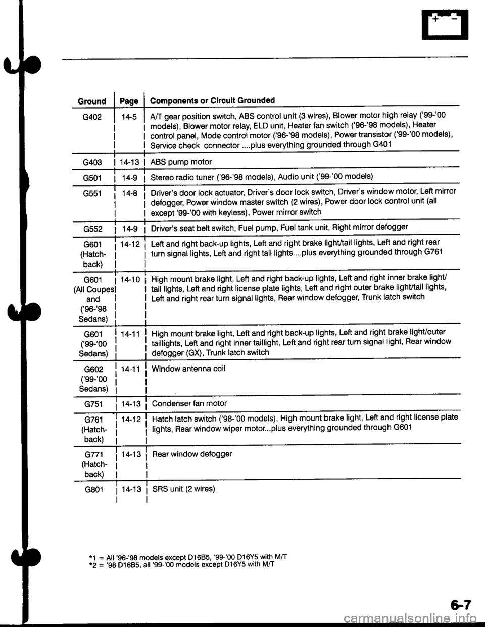
Ground
G402
Components or Clrcult Grounded
Arr gear position switch, ABS control unit (3 wires), Blower motor high relay ('99-'00
models), Blower motor relay, ELD unit, Heater Jan switch ('96-'98 models), Heater
control panel, Mode control motor ('96.�98 models), Power transistor ('99-'00 models),
Service check connector....plus everything grounded through G401
| 14-13 | ABS pump motor
1l-9 i Stereo radio tuner ('96-'98 models), Audio unit ('99-'00 models)
Drivsr's door lock actuator, Driver's door lock switch, Drivefs window motor' Left mirror
defogger, Pow€r window master switch (2 wires), Power door lock control unit (all
except '99-'00 with keyless), Power mirror switch
G55214-9 i Driver's s€at belt switch, Fuel pump, Fuel tank unit, Right mkror defogger
G601
(Hatch-
back)
14-12 iLeft and right back-up lights, Left and right brake lighvtail lights, Lefl and right rear
turn signal lights, Left and right tail lights....plus eveMhing grounded through G761
G601 I 14-10
(All Coupesl
ano
(96198
S6dans)
High mount brake light, Left and right back-up lights, Left and right inner brake lighv
taiilights, Lett and right license plale lights, Lett and right outer brak€ lighvtail lights'
Left and right rear turn signal lights, Rear window deJogger, Trunk latch switch
G601
(99-'oo
Sedans)
G602
('ss-'00
Sedans)
G761
(Hatch-
back)
G771
(Hatch-
back)
14-11
14-12 i
High mount brake light, Left and right back-up lights, Left and right brake lighvouter
taillights, Left and right inner taillight, Left and right rear turn signal light' Rear window
deJogger (GX), Trunk latch switch
Window antenna coil
Hatch latch switch ('98-'00 models), High mount brake light' Left and right license plate
lights, Rear window wiper motor...plus everything grounded through G601
Rear window defogger
14-13 i SRS unit (2 wires)
*1 = All '96-98 models €xcept Dl685, '99100 D16Y5 with M/T*2 = '98 D1685, all '99-'00 models except Dl6Y5 with M/T
e7
Page 1948 of 2189
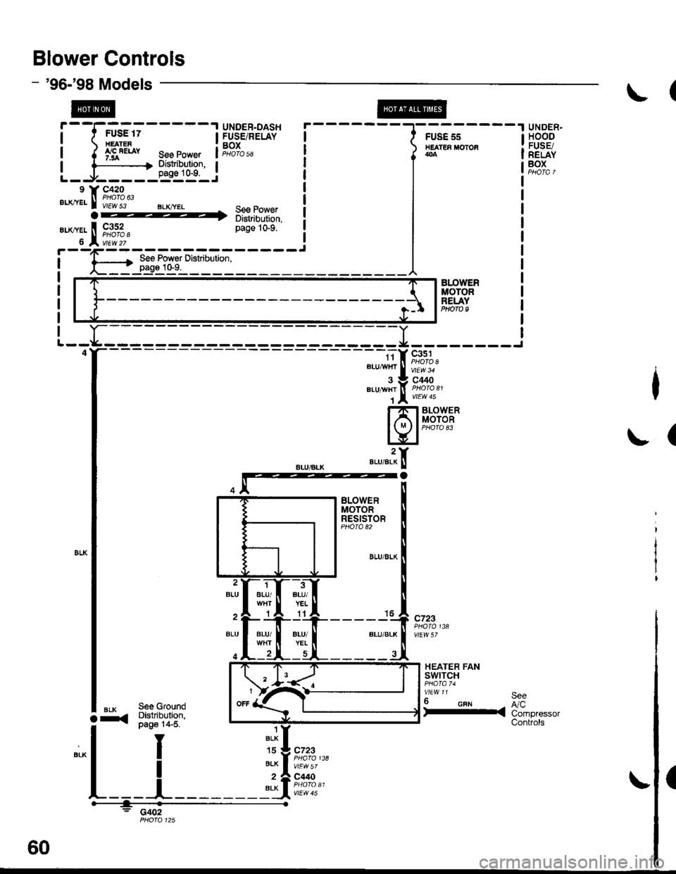
Blower Controls
'96-'98 Models
@
UNDER.HOODFUSE/RELAYBOX
UNDER.DASHFUSE/RELAYBOXPHOTO 5A
BLOWEFnoToRBELAYPEOfO I
HEATER FANSWITCH
6 calrSeeL/cCompressorControls
(
See GroundDbtribution,oaqg 14-5.
See GrorDbtributipage 14.
I
I
_l
ar<
L
- c402
BLU/YEL1l
BLU/
1BLK
BLK
BLK
60
Page 1952 of 2189
![HONDA CIVIC 1998 6.G Repair Manual Air Delivery
- 99-00 Models
a
r--T----.I UNDER-HOOD UNDEB-DASH
| ,ry:i.l? IFUSE/RELAY I t::u:E^tt l:usE/RELAyi
- -{-;;; -
I PJ,.,8.J390 i
-
T;; ;
- - - - -
I H$3,,8
i 1;:t"* ];FPJ", i i m. HONDA CIVIC 1998 6.G Repair Manual Air Delivery
- 99-00 Models
a
r--T----.I UNDER-HOOD UNDEB-DASH
| ,ry:i.l? IFUSE/RELAY I t::u:E^tt l:usE/RELAyi
- -{-;;; -
I PJ,.,8.J390 i
-
T;; ;
- - - - -
I H$3,,8
i 1;:t"* ];FPJ", i i m.](/img/13/6068/w960_6068-1951.png)
Air Delivery
- '99-'00 Models
a
r--T----.I UNDER-HOOD UNDEB-DASH
| ,ry:i.l? IFUSE/RELAY I t::u:E^tt l:usE/RELAyi
- -{-;;; -
I PJ,'.',8.J390 i
-
T;; ;
- - - - -
I H$3,',8
i 1;:t"* ];FPJ", i i m'.u" se€power i "t8L,,
i t i a l'"0 r3l",lli"i:" aL--{..-----J L-J..----5::---:-J
"",":"rfi?ll, '[r;T:1"
-",*"1-J
*-*..l
,n", ".u I lt I
lr !I See Power I See Power Distnbution.I Distribution, U page 1o-9.
,, L::':l------- *Y=l
"*o "."",,t
[
*,:.'.Y%
Irel-
lt
:'l-4riffi
MODECONTROLMOTOR
;L:L{;I{,tt't{ {f
SensorGround grgund
venl
Air mix5Y poientia,reTgrano9 rnrrul
gIouno
RecircSwilcfi switchcommon mput
Recirc S$,itchtED LEDcontrol common
RECIRCULATIONCONTROLMOTORPHOTO 139
CONTROLPANEL
vtEw 76
So€ Roar II Windolv :
a
Htr Ttr =tr ;l *tr :tr *,tr THtr Ttr =tr ;l *tr :tr *tr Ttr
'il
Ti
Battery lgnition Mod€ Mode Mode L4ode Mode l od€(back up) input detrost h€av heat heav vent motorR€circulato Fresh
IJ
Delogger
L------- ---J
HEATERPUSHswtTcHEs
delrost
Air Airmix mixcool hot;;-; J'J - - - J-JL i- 5:- - -
SLK
812
AFN
13
BFN
See GroundDistribution,page 14-5.
c4 t, cl
WHT I ONN
ft++il
c723
F ash/RoclreSwftch
Reclrc.oat LEo
IY
tt
L__l--tGo3,
See RearWindowOetogger
AIR MIXTURECONTROLMOTOR
(
c9 Y cl1
61-2
Page 1953 of 2189
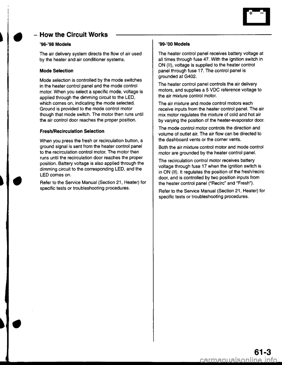
- How the Circuit Works
'96198 Models
The air delivery system directs the flow of air used
by the heater and air conditioner systems.
Mode Selection
Mode selection is controlled by the mode switches
in the heater control panel and the mode control
motor. When you select a specific mode, voltage is
applied through the dimming circuit to the LED,
which comes on, indicating the mode selected.
Ground is orovided to the mode control motor
though that mode switch. The motor then runs until
the air control door reaches the proper position.
Fresh/Recirculation 56lection
When you press the fresh or recirculation button, a
ground signal is sent from the heater control panel
to the recirculation control motor. The motor then
runs until the recirculation door reaches the proper
position. Battery voltage is also applied through the
dimming circuit to the corresponding LED, and the
LED comes on.
Refer to the Service Manual (Section 21, Heater) for
specitic tests or troubleshooting proc€dures.
'99J00 Models
The heater control panel receives battery voltage at
all times through fuse 47. With the ignition switch in
ON (ll), voltage is supplied to the heater control
panel through fuse 17. The control panel is
grounded at G402.
The heater control panel controls the air delivery
motors, and supplies a 5 VDC reterence voltage to
the air mixture control motor.
The air mixture and mode control motors each
receive inputs trom the heater control panel. The air
mix motor regulates the mixture of cold and hot air
by varying the position of the heater-evaporator doot
The mode control motor controls the direction and
volume of outlet air. The air flow can be directed to
the dashboard vents or the corner vents.
Both the air mixture control molor and mode control
motor are grounded by the h€aler control panel.
The recirculation control motor receives battery
voltage through fuso 17 when the ignition swilch is
in ON (ll). lt regulates the position of the fresh/recirc
door, and is controlled by two position inputs from
the heater control panel ("Recirc" and "Fresh").
Refer to the Service Manual (Section 21, Heater) tor
specific tests or troubleshooting procedures.
61-3
Page 1956 of 2189
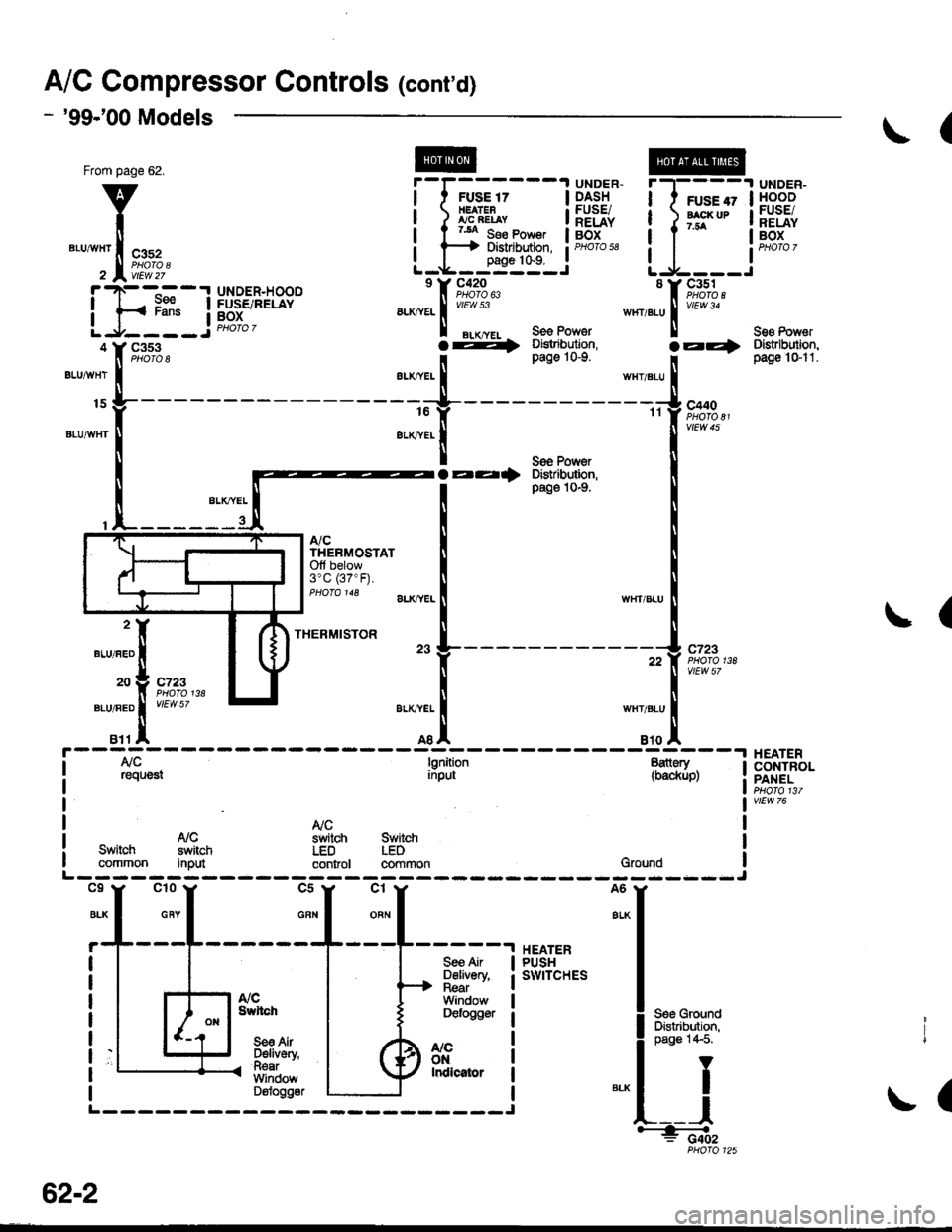
AiC Compressor Gontrols (cont'd)
- '99-'00 Models
From page 62.
v
I*"-ilii.,"r,
ihtli4
BLUAVHT
15
6LUAVHT
UNDER.HOODFUSE/RELAYBOX
Seg Pow6rDistrlbutiofl,pag€ 'l Gl1-c353PHO|O 8
l[,,*
';.!, "'""
,c,/cSwitch switchcommon itput
a,/cTHERMOSTATOlt below3"C (37"F).
THERMISTOR
(
B11A A8A B'IO |'r--:=---I A/C lgnition B€ttery II request input (backup) :
".j:[ru*,,ry "..;X
{;[
vtEW 57
HEATERCONTROLPANEL
l'lCswitch SwitchLgD IEDcodrol cormonGrouod
See AirD€livery,RgarWindowD€foggar
BIK
cl
ORN
c5
GBN
r,/cOt'llndicatof
HEATERPUSHswrTcHEs
t/cSwltch
S€e AirDelivefy,RearWindowDslogg6f
See GroundDist.ibdion,page 1,1-5.
Y
I(
=ffi;
(
.I UNDER.
I HOODi FUSE/I RELAYI Box
IJ
62-2
PHOfO 125
Page 1957 of 2189
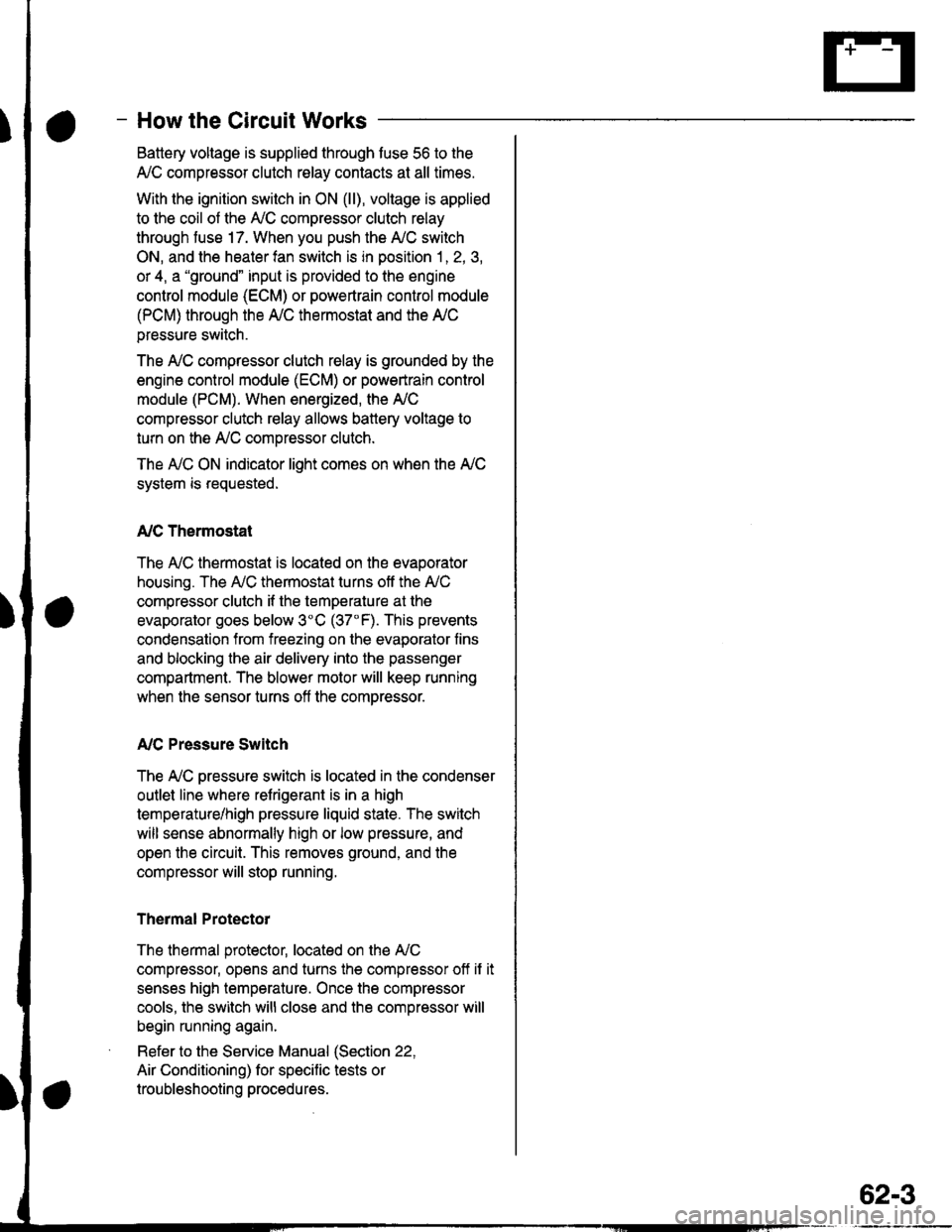
- How the Circuit Works
Battery voltage is supplied through tuse 56 to the
A,/C compressor clutch r€lay contacts at all times.
With the ignition switch in ON (ll), vollage is applied
to the coil of the A,/C compressor clutch relay
through fuse 17. When you push the A,/C switch
ON, and the heater fan switch is in position | , 2, 3,
or 4, a "ground" input is provided to the engine
control module (ECM) or powertrain control module
(PCM) through the l'lC thermostat and the l'lC
pressure switch.
The A,/C compressor clutch relay is grounded by the
engine control module (ECM) or powertrain control
module (PCM). When energized, the A'lC
compressor clutch relay allows battery voltage to
turn on the A,/C comDressor clutch.
The A,/C ON indicator light comes on when the A,/C
system is requested.
A,/C Thermostat
The A'lC thermostat is located on the evaoorator
housing. The A,/C thermostat turns off the A,/C
compressor clutch if the temperature at the
evaporator goes below 3'C (37'F). This prevents
condensation from freezing on the evaporator fins
and blocking the air delivery into the passenger
compartment. The blower motor will keep running
when the sensor turns off the comDressor.
A,/C Pressure Switch
The fuC oressure switch is located in the condenser
outlet line where refrigerant is in a high
temperature/high pressure liquid state. The switch
will sense abnormally high or low pressure, and
open the circuit. This removes ground, and the
compressor will stop running.
Thermal Protectot
The thermal protector, located on the A,/C
compressor, opens and turns the compressor off if it
senses high temperature. Once the compressor
cools, the switch will close and the compressor will
begin running again.
Refer to the Service Manual (Section 22,
Air Conditioning) for specific tests or
troubleshooting procedures.
62-3
Page 1960 of 2189
![HONDA CIVIC 1998 6.G Repair Manual Fans (contd)
- 99-00 Models
Switch"common
a,/cTHERMOSTATOff below3C (37" F).
rla
iTm,il-- l5;i;T iln"lgg1
L_t]stE"_i*-o* !-J-___i
*-"
"W"u
".*L[F*f,l" -*,"."[ftT,;.
I I .-.. Sse Power II , HONDA CIVIC 1998 6.G Repair Manual Fans (contd)
- 99-00 Models
Switch"common
a,/cTHERMOSTATOff below3C (37" F).
rla
iTm,il-- l5;i;T iln"lgg1
L_t]stE"_i*-o* !-J-___i
*-"
"W"u
".*L[F*f,l" -*,"."[ftT,;.
I I .-.. Sse Power II ,](/img/13/6068/w960_6068-1959.png)
Fans (cont'd)
- '99-'00 Models
Switch"common
a,/cTHERMOSTATOff below3'C (37" F).
rla
iTm,il-- l5;i;T iln"lgg1
L_t]stE"_i*-o* !-J-___i
*-"'
"W"u'
".*L[F*f,l"' -*,".'"[ftT,;.'
I I .-.. Sse Power II ',-.', Sse Power I S€€ Pow€r
?+ 3s;iT:3:' ?'4 3ff:?f?l:
OEE I Dbfibution,
I pacp 10.9.
HEATERCONTROLPANEL
vlEw 76
A6
BLK
;+
::--
{***,Pase*11
ItI
rfa
r,/cswitchinputL-----
HEATERPUSHswtTcHEs
A/CSwlbh
See AirDslivery,n6arWindowDelogoor
S€e AltDeliv€ry,BaarWindowD€loggpr
See GroundDistribution,pag€ 1+5.
I
J;-a;
I I 'l rHERMrsroR I Ilt | 23 9--------------2, c723q/ f, ,2tr prtoroz!3a
tttlllnr ar-x,ver- | tn*t,".u IItI
orl "tol---riliii"--
inplt (backup)
i
I
Nclsvritcn Swikh ILED LEDcontrol cofrrnon Ground _ _.i
2Yl
^..._-_I t*-*"!
t2oV c723 I
- -_-\Tgr?;u L
---rF------
requ€si
63-2
a/cONlrdlcalqr