heater switch HONDA CIVIC 1998 6.G Repair Manual
[x] Cancel search | Manufacturer: HONDA, Model Year: 1998, Model line: CIVIC, Model: HONDA CIVIC 1998 6.GPages: 2189, PDF Size: 69.39 MB
Page 1961 of 2189
- How the Circuit Works
Radiator Fan
Voltage is provided at all times to the radiator fan
relay (contacts) through fuse 57. With the ignition
swilch in ON (ll), voltage is provided to the coil of
the relay through luse 17.
The radiator tan relay can be grounded through
either the engine coolant temperature switch or the
engine control module (ECM) or powertrain control
module (PCM).
The engine coolant temperature switch grounds
the radiator fan relay (coil) when the engine
coolant temperature exceeds 199'F (83'C). The
switch opens when coolanl temperature
decreases 3'- 8'C.
Condenser Fan
Voltage is provided at all times to the condenser fan
relay (contacts) through fuse 56. With the ignition
switch in ON (ll), voltage is provided to the coil of
the relay through fuse 17. When you push the A'lC
switch and put the heater fan switch in 1, 2,3, o( 4
position, the ly'C thermostat comes on, the
condenser fan relay energizes, and the condenser
fan motor runs.
A,/C Thermostat
The A,/C thermostat is located on the evaporator
housing. The A,/C thermostat tums off the A/C
compressor clutch if the temperature at the
evaporator goes below 3'C (37'F). This prevents
condensation from freezing on the evaporator fins
and blocking the air delivery into the passenger
compartment. lf the temperature goes below 3'C
(37"F) tuming off the Ay'C thermostat, ground will be
removed from the condenser fan relay. This will
deenergize the relay and remove voltage from the
condenser fan motor causing the fan to stop running.
Reter to the Service Manual (Section 23, Eleckical)
for specific tests or troubleshooting procedures.
63-3
Page 1963 of 2189
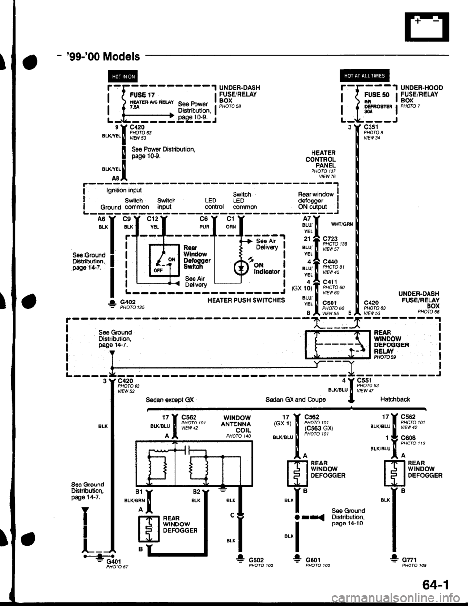
- '99-'00Models
t@
J
See Power0istribution,pag€ 1&9.
r
I
I
Lc420
vtEw 53".*:.f
!
"T.I
FUSE '7HEJT'EF AIC RETAY7JA
UNDER-DASHFUSE/RELAYBOXPHOfO 58
r-r---1 UNDER-HOOD
| ( #tt* IFUsE/RELAY
I t sl*t-' '"o'o'
L-*----J3 Y C3s1
Ss6 Pows Dist bution,pag€ 10-9.
Sn itchLEDcommon
c420PHOTO 63vtEw 53
HEATERCONTROLPANEL
II
I
lgnition inpd
Swiich SlitohGroulld co{Y}rnon inMLEDgontrol
Rear winoow Idofogger Igl",,ry'_l
A6
ALX
S9a €roundDistr&dbn,P.go 1it-7.
c12
YEL
c9
BLK
r'
c6
PUR
c1
ORN
A7BLU/YEL
21
BLU/YEL
BLU/YEL
4(GX 10)
BLU/YEL
8
- Se€ Air ;D6livory
ONIndlcitor
wlIT/GFI{
c723PHO|O 138
c440PHO|O 81vtEw 45
c411PHOTO 60vtEw 60
c501
vtEwss 5
R€aIWlndowDcroggerSultch
56€ AirDeliv€ryL------- ---J
HEATER PUSH SWITCHESUNDEN.DASHFUSE/RELAYBOXPHO|O 5e
I
I
I
I
See GoundDistdbltion,page 14-7.
NEABwlNoolyDEFOGGENF€I.AYPrrolo 59
I
I
I
I
I
cssl
vtEw 47
Halchback
"*1[ ftTi.:-
wtNDowANTENNAcotL{cx'l) T 9,*%,,
",-"",-,
1
[93ff''n'*'
to!.'IFI REARI J I wrNDow
lll
DEFoGGER
".-i."tr ftTi",,'
t V F,9"oB ",erxialul I
ffiff$Eex,"
*"r'
I
I
* cttrPHOfO 10A
Sre GroundDFtrtbditm,pago 1+7.
I
t_
".":il
H
eY
82
ALK*-r"
arr<
-.1
!
S€9 GrolndDistribtdion,pag€ 1+ 10
*r: G401* csozG601
I. G,rc2
PHOIO 57
BEARwtNDowDEFOGGER
64-1
Page 1964 of 2189
Rear Window Defogger
- How the Circuit Works
'96198 Models
Voltage is applied at all limes through tuse 50 to the
rear window detogger relay (contacts). With the
ignition switch in ON (ll), voltage is applied through
tuse 16 to the rear window defogger switch.
When you turn the switch ON, voltage is applied to
the defogger timer circuit. The timer circuit supplies
voltage to the rear window defogger relay (coil). The
relay energizes and supplies voltage to the rear
window defogger. The defogger grid then heats the
rear window to remove any condensation from the
glass.
The defogger timer circuit will automatically turn off
the rear window defogger after about 25 minutes.
Refer to the Service Manual (Section 23, Electrical)
for specific tests or troubleshooting procedures.
'99100 Models
Voltage is applied at all times through fuse 50 to the
rear window delogger relay (contacts). With lhe
ignition switch in ON (ll), voltage is applied through
fuse 16 to the heater control oanel.
When you turn the rear window defogger switch
ON, a signal is sent to lhe defogger timer circuit
built-into the heater control oanel. The timer circuit
supplies voltage to the rear window defogger relay
(coil). The relay energizes and supplies voltage to
the rear window defogger. The defogger grid then
heats the rear window to remove anv condensation
from the glass.
The defogger timer circuit will automatically turn otf
the rear window defogger after about 25 minutes.
Refer to the Seryice Manual (Section 23, Electrical)
for specific tesls or troubleshooting procedures.
64-2
I
a
a
Page 2108 of 2189
-
Component Connector View Index (Views begin on page 202-21
Connector View
ABS Control Unit........ ......63
Audio Unit ('99-'00 models) ......74
Combination Light Switch . . . . . . . . . . . . . . . 64
Combination Wiper Switch . . . . . . . . . . . . . . 65
Cruise Control Unit.... .....43
C\TTTransmission Solenoid ............. 25
Data Link Connector (DLC) ..... 48
Daytime Runnlng Lights Control Unit ..... 66
Engine control Module (ECM) ...........70
Exhaust Gas Recirculation (EGR) Valve
and Lift Sensor (D16Y5 Mfl, D1685) . . . . 10
Gauge Assembly .............71
HazardWarnlngSwitch,,. .,,,...,,,,... 32
Heater Control Panel ('96-'98 models) .....44
Heater Control Panel ('99-'00 models) ...., 76
Heater Fan Switch ('96-'98 models) ,,,.... 11
fniector Control Module (GX) ............77
I/
202-1
Connector View
Integrated Control Unit .......,. 67
f nterfock Control Unit .... ...... 26
Keyfess Door Lock Control Unit . . . . , . . . . . 75
Mode Control Motor ... ........'17
Moonroof Close Relay .. .......13
Moonroof Open Relay ... .......15
PGM-FI Main Relay .. .......... 18
Power Door Lock Conlrol Unil ..... ...... 37
Power Mirror Switch .,... ...... 33
Power Window Master Switch .,.........36
Powertrain Control Module (PCM) .......70
Security Control Unit ..., ..,,... 58
Security Starter Cut Belay ... ...,,,....,, 12
SRS Unit ............. 51
Stereo Radio Tuner ('96-'98 models) ...... 68
Transmission Control Module CICM) .....69
Page 2110 of 2189
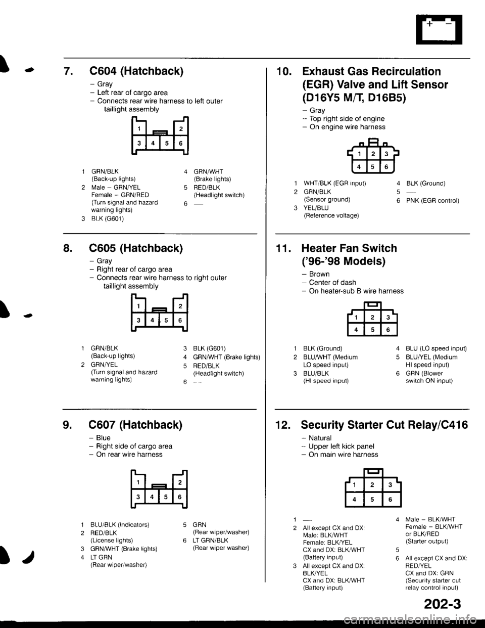
\7. C604 (Hatchback)
GRN/BLK(Back-up lights)
l\4ale GRNIYELFemale - GRN/RED(Turn signaland hazardwarning lights)
BLK (G601)
- Gray- Left rear ol cargo area- Connects rear wire harness to left outer
taillight assembly
4
5
6
1
2
GRNAVHT(Brake lights)
FED/BLK(Headllght switch)
10. Exhaust Gas Recirculation
(EGR) Valve and Lift Sensor
1
2
3
(D16Y5 MfI D1685)
- Gray- Top right side of engine- On engine wire harness
WHT/BLK (EGR input)
GRN/BLK(Sensor ground)
YEUBLU(Reference voltage)
4
5
6
BLK (Ground)
PNK (EGR control)
of cargo area
rear wire harness to right outer
assembly
n- -n
a t | _ a2a
l3I4t5tttl
IJ
I
8. C605 (Hatchback)
- Gray- Right rear- Connects
taillight
GRN/BLK(Back-up lights)
GRNTYEL(Turn signaland hazardwarning lights)
3
4
5
6
1
2
BLK (G601)
GFNAVHT (Brake lights)
RED/BLK(Headlight switch)
11. Heater Fan Switch
('96-'98 Models)
- Brown
Center of dash- On heater-sub B wire harness
BLK (Ground)
BLUAVHT (L4edium
LO speed input)
BLU/BLK(Hl speed input)
4
5
6
1
2
3
BLU (LO speed input)
BLU/YEL (Medium
Hlspeed input)
GFIN (Blowerswitch ON input)
9. C607 (Hatchback)
- Blue- Right side o{ cargo area- On rear wire harness
BLU/BLK (lndicators)
RED/BLK(License lights)
GBN,ryVHT (8rake lights)
LT GBN(Rear wiper/washe0
5
6
1
2
3
4
GRN(Rear wiper/washer)
LT GRN/BLK(Rear \/iper washer)
)/
202-3
12. Security Starter Cut Relay/C416
- Natural* Upper left kick panel- On main wire harness
1
2Allexcept CX and DXI[,4ale: BLK,^r'r'HTFemale: BLKI/ELCX and DXi BLI(WHT(Battery input)
All except CX and DX:BLK^/ELCX and DX: BLK/WHT(Baftery input)
[.4ale - BLK/WHTFemale - BLKAVHTor BLKRED(Starter output)
All excepi CX and DX:RED/YELCX and DX: GRN(Security starter c!1relay control inpul)
5
6
tl3'
Page 2120 of 2189
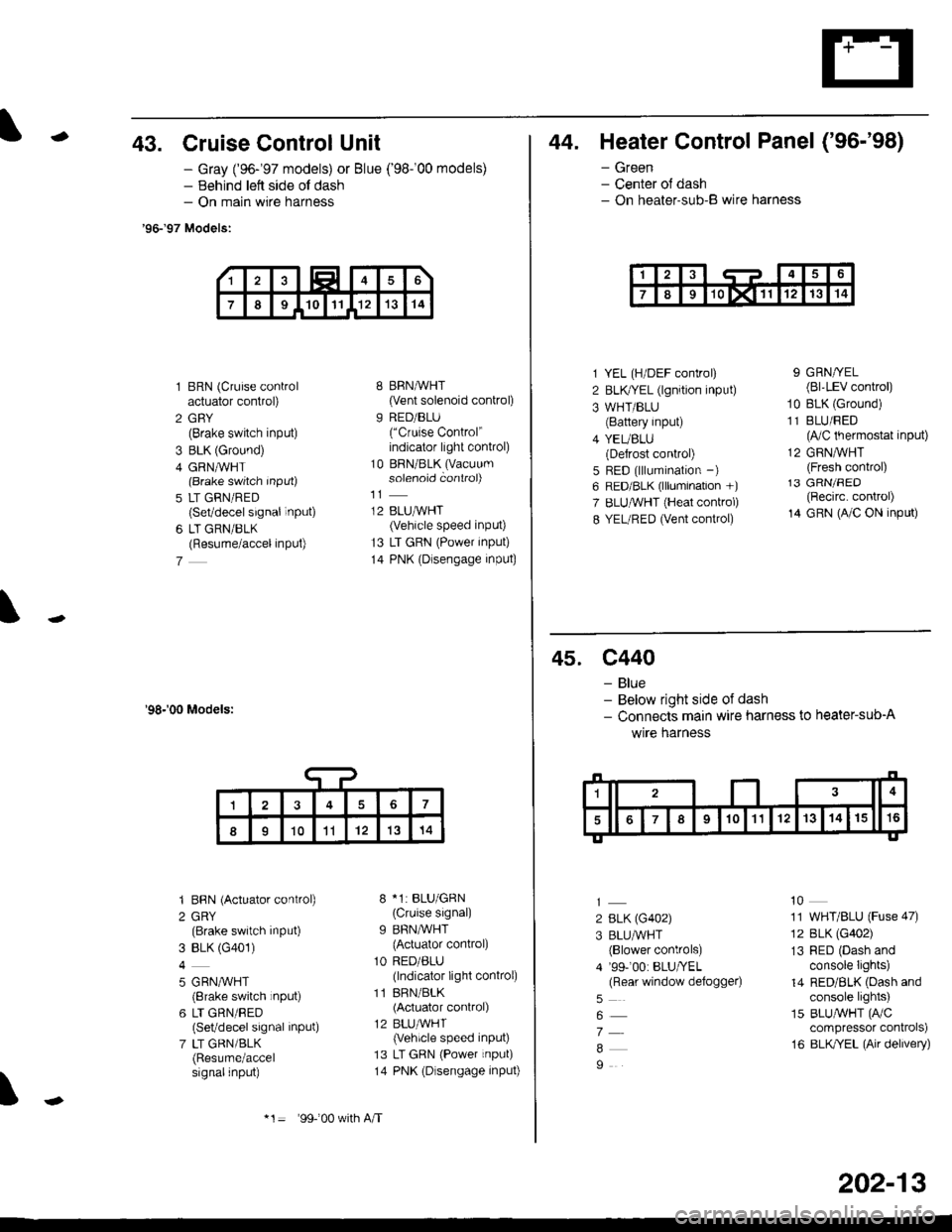
-43. Cruise Control Unit
- Gray ('96-'97 models) or Blue ('98-'00 models)- Behind lett side ol dash- On main wire harness
'96-'97 Models:
1 BRN (Cruise controlactuator control)
2 GBY(Brake switch input)
3 BLK (Ground)
4 GRN,ryVHT(Brake switch Input)
5 LT GRN/RED(Set/decel signal inPUt)
6 LT GRN/BLK(Resume/accel inPut)
7
'98-'00 Models:
'I BBN (Actuator control)
2 GRY(Brake switch input)
3 BLK (G401)
4
5 GRN,^/VHT(8rake switch rnput)
6 LT GRN/RED(Set/decel signal inPut)
7 LT GRN/BLK(Resume/accelsignalinput)
8 BRN,AiVHT(Vent solenoid control)
9 RED/BLU("Cruise Control"indicator light conkol)
10 BRN/BLK (Vacuum
solenoid controi)
12 BLUMHT(Vehicle speed input)
13 LT GRN (Power input)
14 PNK (Dlsengage input)
8 *1: BLU/GRN(Cruise signal)
9 BFN/WHT
{Actuator control)
1O RED/ALU(lndicator light conkol)
11 BRN/BLK(Actuator control)
12 BLU,ryVHT(Vehicle speed input)
13 LT GRN (Power input)
14 PNK (Dlsengage input)
\
17
II1011'121314
*1= 99-'00 w(h A/T
202-13
44. Heater Control Panel ('96-'98)
- Green- Center ol dash- On heater-sub-B wire harness
1 YEL (H/DEF control)
2 BLKTYEL (lgnition input)
3 WHT/BLU(Battery input)
4 YEUBLU(Defrost control)
5 RED (lllumination -)
6 RED/BLK (lllumination +)
7 ELUruVHT (Heat conkol)
8 YEL/RED (Vent control)
9 GRN/YEL(Bl'LEV control)
10 BLK (Ground)
11 BLU/FED(lVC thermostat input)
12 GRNMHT(Fresh control)13 GRN/FED(Recirc. control)
14 GRN (A/C ON input)
45. c440
- Blue- Below right side of dash- Connects main wire harness to heater-sub-A
wrre narness
2 BLK (G402)
3 BLU/WHT(Blower controls)
4 '99-'00: BLU/YEL(Rear window defoggeo
7
9
10
11 WHT/BLU (Fuse 47)
12 BLK (G402)
13 RED (Dash andconsole Iights)
14 RED/BLK (Dash andconsole lights)
15 BLUAVHT (FVC
compressor conkols)
16 BLK/YEL (Air delivery)
Page 2124 of 2189
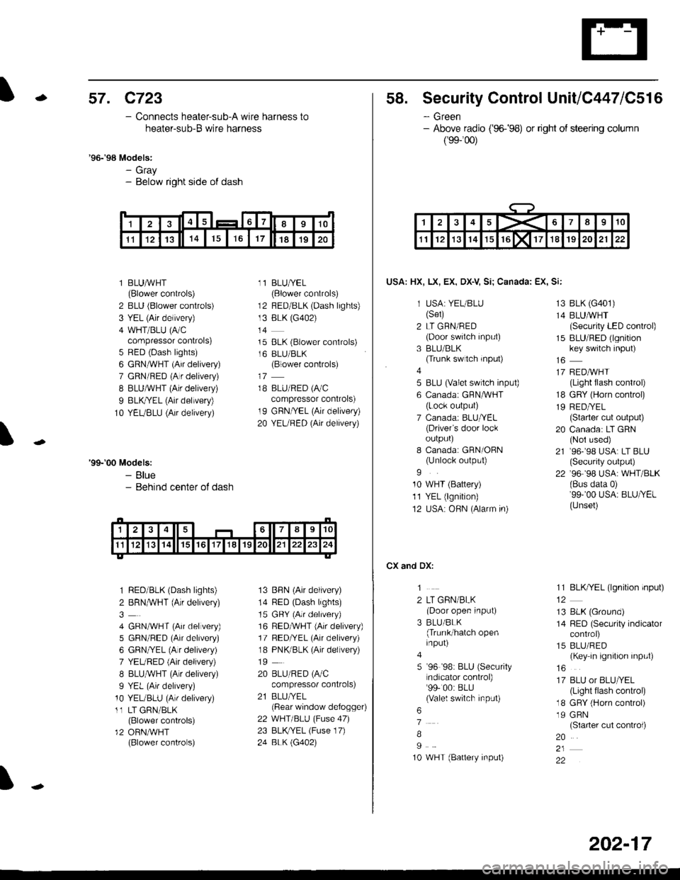
-57. c723
- Connects heater-sub-A wire harness to
heater-sub-B wire harness
'96-'98 Models:- Gray- Below right side of dash
l BLUAVHT(Blower controls)
2 BLU (Blower controls)
3 YEL (Air delivery)
4 WHT/BLU (A/Ccompressor controls)
5 RED (Dash lights)
6 GRN^VHT (Air delivery)
7 GRN/RED (A r delivery)
I BLUAVHT (Air delivery)
9 BLK,ryEL (Air delivery)
10 YEUBLU (Air delivery)
11 BLU/YEL(Blower controls)
12 BED/BLK (Dash lights)
13 BLK (G402)
t4
15 BLK (Blower conlrols)
16 BLU/BLK(Blower controls)
18 BLU/RED (A/C
compressor controls)
19 GRN/YEL (Air delivery)
20 YEURED (Air delivery)
'99-'00 Models:- Blue- Behind center ot dash
1 RED/BLK (Dash lights)
2 BRNMHT (Au delivery)
4 GRNA/VHT (Air delvery)
5 GBN/BED (Air delivery)
6 GRN/YEL (Alr delivery)
7 YEURED (Air delivery)
8 BLU,ryVHT (Au delivery)
9 YEL (An delivery)
10 YEUBLU (Arr delivery)
11 LT GRN/BLK(Blower controls)
12 ORN,AiVHT(Blower controls)
13 BBN (Air delivery)
14 RED (Dash lights)
15 GRY (Air delrvery)
16 RED,ryVHT (Air delivery)
17 RED/YEL (Air delivery)
18 PNK/BLK (Air delivery)
19
20 BLU/RED (A/C
compressor controls)
21 BLUI/EL(Bear window defogger)
22 WHT/BLU (Fuse 47)
23 BLKryEL (Fuse 17)
24 BLK \G402)
I
1415617I910
1l1213141617181920
58. Security Control UnitiC447lC516
- Green- Above radio ('96-�98) or right of steering column
(99-'�00)
USA: HX, LX, EX, DX-V Si; Canada: EX, Si:
1 USA: YEUBLU(Set)
2 LT GRN/RED(Door swiich input)
3 BLU/BLK(Trunk switch rnput)
4
5 BLU (valet switch inpu0
6 Canadai GFNAVHT(Lock output)
7 Canada: BLU/YEL(Driver's door lockoulpurJ
I Canada: GRN/OBN(Unlock output)
9
10 WHT (Battery)
11 YEL (lgnition)
12 USA: OHN (Alarm in)
CX and DX:
1
2 LT GRN/BLK(Door open input)
3 BLU/BLK(Trunk/hatch openinput)
5 '96 '98: BLU (Security
ndicator control)99- 00: BLU(Valel switch input)
6
7
B
I
10 WHT (Battery input)
13 BLK (G401)
14 BLUMHT(Security LED conkol)
15 BLU/RED (lgnitionkey switch input)
17 REDAVHI(Light flash control)
18 GRY (Horn conkol)
19 RED/YEL(Starter cut output)
20 Canada: LT GRN(Nol used)
21 ,96-,98 USA: LT BLU(Security output)
22 '96 98 USA: WHT/BLK(Bus data 0)'99-'00 USA: BLU/YEL(Unset)
11 BLK/YEL (lgnition input)
13 BLK (Ground)
14 RED (Security indicatorcontrol)
15 BLU/RED(Key in ignition input)
16
17 BLU or BLU/YEL(Light tlash control)
18 GRY (Horn control)
19 GRN(Slarter cut control)
20
22
1><678910
1112131415rGlxllT1819202122
202-17
Page 2140 of 2189
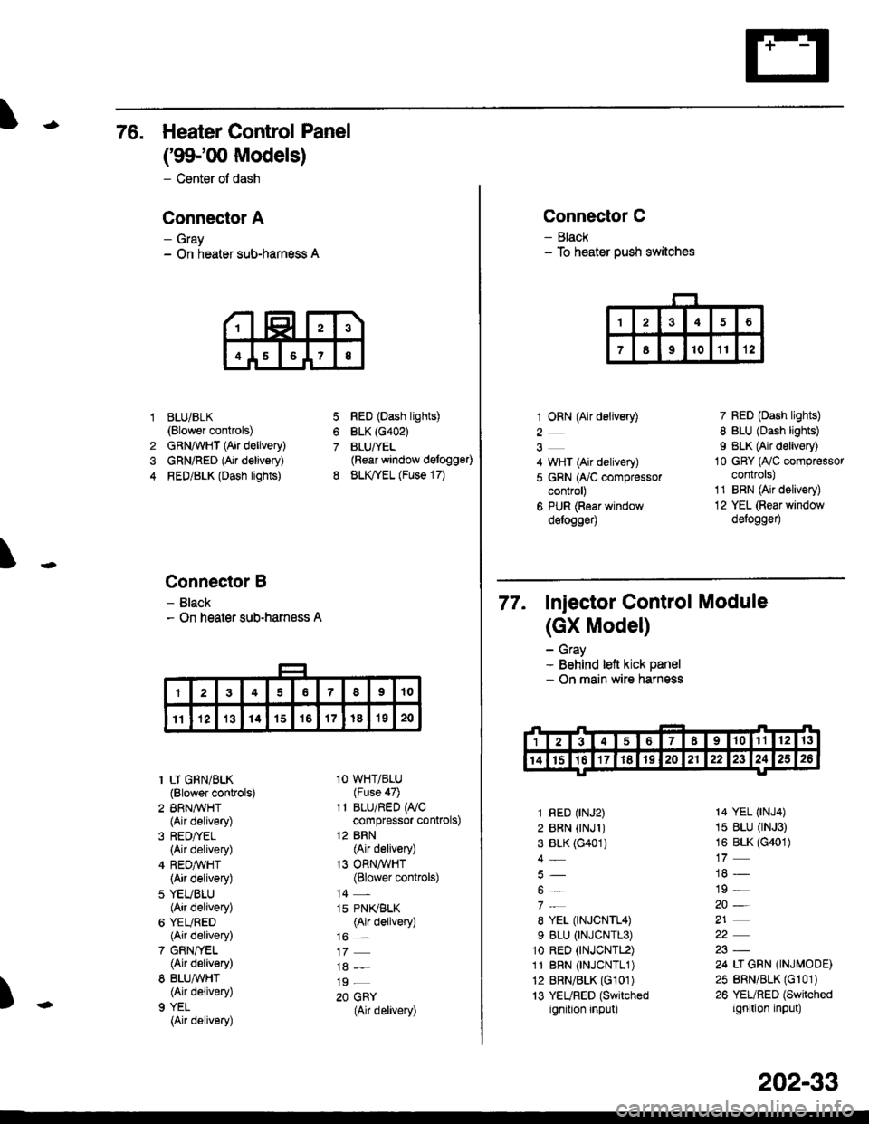
76. Heater Control Panel
('99100 Models)
- Center of dash
Conneclor A
- Gray- On heater sub-harness A
BLUi BLK(Blower controls)
GRNAVHT (Air delivery)
GRN/RED (Air delivery)
RED/BLK (Dash lights)
Connector B
- Black- On heater sub-harness A
7
8
1
4
RED (Dash lights)
BLK (G402)
BLUfYEL(Rear window defogg€0
BLK,TYEL (Fuse 17)
\
)
1 LT GRN/BLK(Blower controls)
2 BRN,A/VHT(Air delivery)
(Air delivery)
4 REDA/VHT(Air delivery)
5 YEUBLU(Air delivery)
6 YEURED(Air delivery)
7 GRN/YEL(Air delivery)
8 BLU,ryVHT(Air delivery)
9 YEL
{Air delivery)
1O WHT/BLU(Fuse 47)
11 BLU/RED WCcompressor controls)
12 BRN(Air delivery)
13 ORNAVHT(Blower controls)
14 -
15 PN(BLK(Air delivery)
16 _
19 _
20 GRY(Air delivery)
Connector C
- Black- To heater push switches
1 ORN (Air delivery)
2
4 WHT (Air delivery)
5 GRN (ry'C compressorcontrol)
6 PUR (Roar windowdelogge4
7 RED (Dash lights)
8 BLU (Dash lights)
I BLK (Air delivery)
10 GRY (Ay'C compressorcontrols)
1'1 BRN (Air delivery)
12 YEL (Rear window
defogge0
77. Injector control Module
(GX Model)
- Gray- Behind left kick panel- On main wire harness
1 RED (rNJ2)
2 BRN (rNJl )3 BLK (G401)
4_
8 YEL (TNJCNTL4)
9 BLU (TNJCNTL3)
1o RED (tNJCNTL2)
11 BRN 0NJCNTL1)12 BRN/BLK (G101)
13 YEURED (Switched
ignition input)
14 YEL (tNJ4)
15 BLU (rNJ3)
16 BLK (G401)
19 -
20-
21
24 LI GRN (INJMODE)
25 BRN/BLK (Gr 01)
26 YEURED (Switched
ignition input)
202-33
Page 2185 of 2189
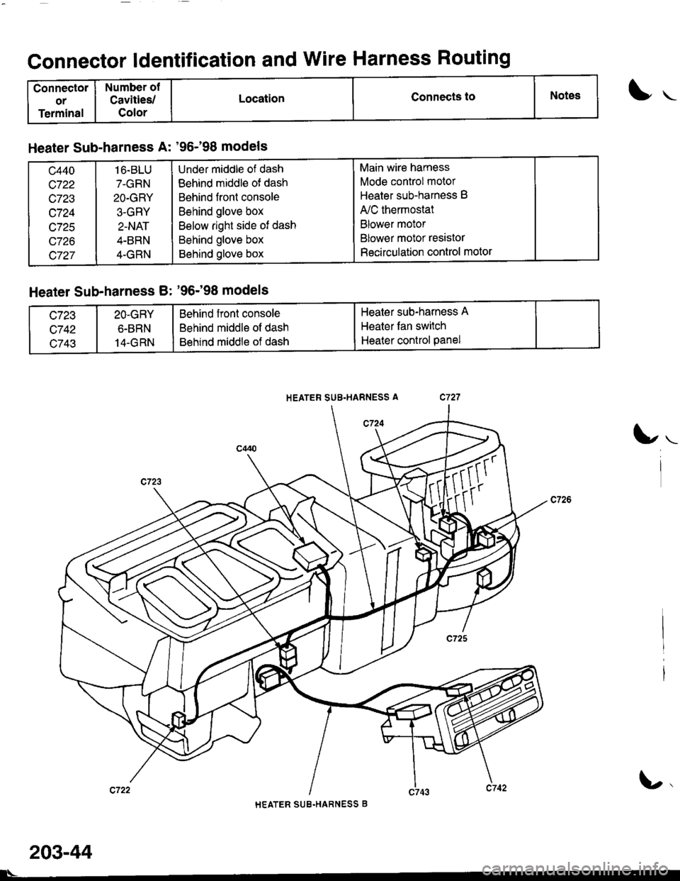
Connectol
or
Terminal
Number of
Cavities/
Color
LocationConnects toNotes
Connector ldentification and Wire Harness Routing
HEATER SUB.HARNESS A
1"t-
Heater Sub-harness A: '96-'98 models
c440
c722
c723
c724
c725
c726
c727
1 6-BLU
7.GRN
2O.GRY
3-GRY
2.NAT
4-BRN
4.GRN
Under middle of dash
Behind middle ot dash
Behind front console
Behind glove box
Below right side of dash
Behind glove box
Behind glove box
Main wire harness
Mode control motor
Heater sub-harness B
A,/C thermostat
Blower motor
Blower motor resistor
Recirculation control motor
Heater Sub-harness Bt '96;98 models
c743
2O-GRY
6-BRN
14-GRN
Behind front console
Behind middle of dash
Behind middle of dash
Heater sub-harness A
Heater fan switch
Heater control panel
u.
HEATER SUB.HARNESS B
l\-
203-44