Model HONDA CIVIC 1998 6.G Workshop Manual
[x] Cancel search | Manufacturer: HONDA, Model Year: 1998, Model line: CIVIC, Model: HONDA CIVIC 1998 6.GPages: 2189, PDF Size: 69.39 MB
Page 942 of 2189
Electrical Troubleshooting ('99 - 00 Models)
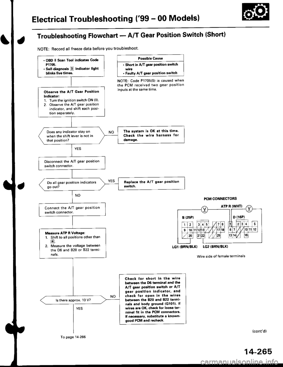
Troubleshooting Flowchart - A/T Gear Position Switch (Short)
NOTE: Record all freeze data before you troubleshoot.
Po3sible Cause
. Short in A/T gear po3ition 3witch
. F.ulty A/T ge6r Position switch
NOTE: Code P1705(5) is caused when
the PCM received two gear Positioninputs at the same time.
PCM CONNECTORS
LGl (BRN/8LKI LG2 (BRN/8LKI
Wire side of female terminals
(cont'd)
14-265
B t25Pt llO(16P1
. oBD ll scln lool indicats code
P't705.. Self-diagnosb E indicator light
blinks fivetim€s.
Obseive tho A/T Gear Polition
lndicetor:1. Turn the ignition switch ON (ll).
2. Observe the A,/T gear positaon
indicator, and shift oach Posi-tion separately.
Tho ry3t6m is OK at this tims.
Check th€ wiro hsrno!! tor
damage.
Does any indicator stay on
when the shift lever is not an
that position?
M.Furo ATP R Vohtge:1. Shift to all positions other than
E.2. Measure the voltage between
the D6 and 820 or 822 termi'
nals,
Chock for lhort in tho wit€
betwe€n the D6 telminal and thg
A/T ge.r position 3witch or A/T
gear po3ition indicttoi, !nd
chcck for open in the witgs
botwo€n the 820 lnd 822 tetmi_n.ls and body g.ound (G1011. F
wiro3 ere OK, check tor loo3o ter'
minal fit in the PrCM connoctors.ll n6c€3sary, 3ubstitute a known-good PCM and rochock.
ls there approx. 10 V?
To page 14 266
Page 943 of 2189
Electrical Troubleshooting ('99 - 00 Models)
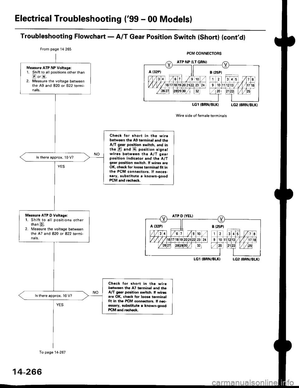
Troubf eshooting Flowcharl - AIT Gear Position Switch {Short) {cont,d}
From page 14 265
LGl IBRN/BLK) LG2 {BRN/BLK}
Wire side of female terminals
A t32Pl jl B {25P)
ATP D (YEL)
LG1 {BRN/ALKILG2 IBRN/BLK)
Measure ATP NP Voltage:'1. Shift to all positions other thanEorI2. Measure the voltage betweenthe A9 and 820 or 922 te(mi-nals.
Check for short in the wirebetwoen ths Ag terminal and theA/T gerr position switch, .nd inthe E .nd E position 3ignalwiros botween the A/T gearposition indic.tor and the A/Tgear positaon switch. lf wircs .reOK, check tor loose terminal tit inthe PCM connectols. lf n€ces-3ary, substitute a known-goodPCM and rocheck.
ls there approx. 10 V?
Me.sure ATP D Vohago:1. Shift to all positions otherthan E.2. Measure the voltage betweenthe 47 and 820 ot 822 tet-r'i-nals,
Check tor 3hort in lhe wireb€twaen thc A7 terminel and theA/T g6ar position switch. lf wir.sare OK, ch.rck to. loose terminalfit in th6 PCM connectoF. lf nsc-ossary. substhute a known-goodPCM and ..check.
ls there approx. 10 V?
a l32Pl ll B (25P1
To page 14-267
14-266
Page 945 of 2189
Electrical Troubleshooting {'99 - 00 Models)
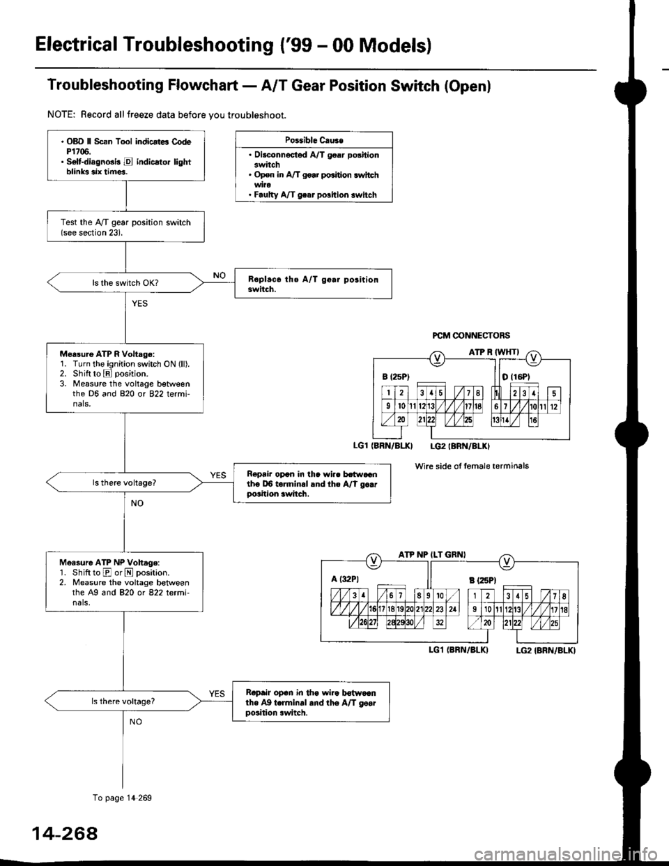
Troubfeshooting Flowchaft- AIT Gear Position Switch (Openl
NOTE: Record allfreeze data before vou troubleshoot.
Po$ible Cau3e
. Oilconnected A/T goar positionswitch. Op€n in A/T go.r po.ition switchwi?o. Faulty A/T gear polition switch
PCM @NNECTORS
(BRN/BI.XI LG2IBRN/BLKI
wire side of fomale terminals
I-G1 (BRN/BLKILG2 {BRN/BLK)
B {25P) I tO (16P1
ATP NP ILT GRNI
A t:r2Pt Il s tzspt
. OBD ll Scan Tool indicstE CodeP1706.. Selt-diagnGi! E indicato. lightblinks six tim€a.
Test the IVT gear position switch(see section 23).
Measu.e ATP R Voltage:1. Turn the ignition switch ON (ll).2. Shift to E position.
3. Measure the voltage betweenthe D6 and 820 or 822 termi-nals,
Ropair opcn in the wi.. hr.raGnth6 DO torminrl lnd the A/t g..rposition awitch.
Measure ATP NP Vohage:'1. Shift to E or N position.2. Measure the voltage betweenthe A9 and 820 ot 822 letmi-nals,
Ropair op6n in th€ wiro b€{woanthe Ag t.rminal and the A/T go..position .witch.
To page 14 269
14-264
Page 947 of 2189
Electrical Troubleshooting {'99 - 00 Models}
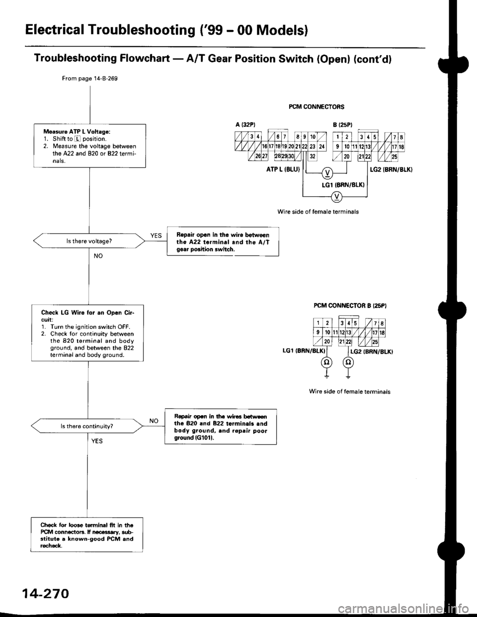
Troubleshooting Flowchart - A/T Gear Position Switch (Openl (cont'dl
Bepair opon in the wiro bgtw€enlho A22 torminal and the A/Tgoar poihion lwitch.
PCM CONNECTORS
B (25P1
LGT (BFN/ALK}
PCM CONNECTOR B I25PI
12.15 / 7I
9't0l1Br1/l/41it8
ll lLG2
o) (o)
IBRN/BLKI
Wire side of female terminals
From page 14-8-269
Msasuro ATP L Voftage:1. Shiftto E position.
2. Measure the voltage betweenthe A22 and 820 or 822 termi-nals,
Check LG Wiro for .n Open Cir-cuit:']� Turn the ignition switch OFF.2. Check lor continuity betweenthe 820 t€rminal and bodyground, and between the 822terminal and body ground.
Ropai' op.n in the wir€a botw.€nthe 820 rnd 822 toJminals .ndbody ground, and .opsi. poolground (Gl01l.
Check tor loose te.minal frt in th6PCM conn€ctors, lf n€cessary, sub-stitut€ a knowo-good PCM anda6check,
Wire side of female terminals
14-270
Page 949 of 2189
ElectricalTroubleshooting ('99 - 00 Models)
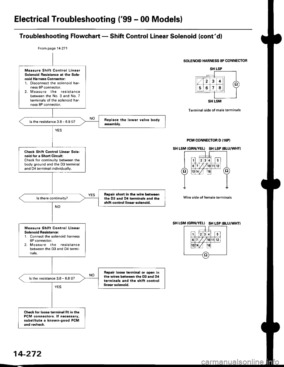
Troubleshooting Flowchart - Shift Gontrol Linear Solenoid (cont'dl
SOI."ENOID HARNESS 8P CONNECTOR
Terminal side of male terminals
PCM CONNECTOR D {16P}
SH LSM IGRN/YELI SH LSP {BLU/WHTI
Wire side oI temale terminals
SH LSM {GRN/YELI SH LSP IALU/WHT}
tuom page 14 271
Measure Shift Control LinearSolenoid R6sistance at the Sole-noid Hrrness Connector:1. Disconnect the solenoid harness 8P connector.2. Measure the resistancebetween the No. 3 and No- 7terminals oI the solenoid harness 8P connector,
ls the resistance 3.8 - 6.8 o?
Check Shift Control Lin€ar Sole-noid tor a Short Circuit:Check for continuity between thebody ground and the D3 terminaland D4 terminal individually.
Rep.ir short in th€ wir€ tr€twlrenihe D3 and D4 torminab .nd theshift cont.ol line.. solenoid.
Measure Shitt Conirol LineerSolenoid Resbtance:1. Connect the solenoid harness8P connector.2. Measure the resistancebetween the D3 and D4 termi-nats.
Repeir loose ierminrl or open inthe wire3 between tho D3 and D4terminals end the shift controllinear solenoid.
ls the resistance 3.8 - 6.8 O?
Check tor loose terminal fit in thePCM connector3, It necessary,substitute a known-good PCMand recheck.
SH LSP
SH LSM
14-272
Page 951 of 2189
Electrical Troubleshooting ('99 - 00 Models)
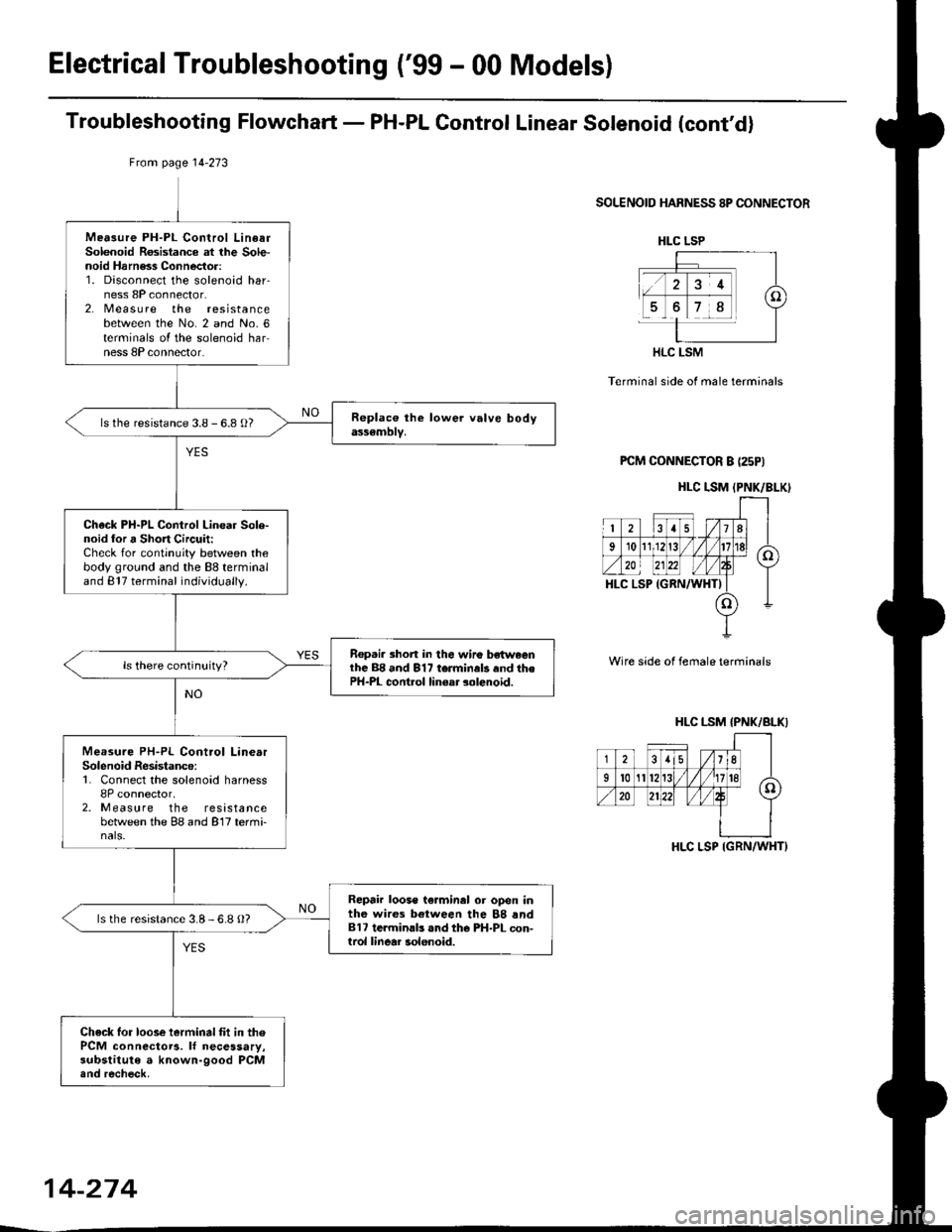
Troubleshooting Flowchart - PH-PL Gontrol Linear Solenoid (cont'd)
From page l4-273
SOLENOID HARNESS 8P CONNECTOR
Terminal side of male terminals
PCM CONNECTOR B (25PI
Wire side of female terminals
Mea3ure PH-PL Control LinearSolenoid Rosistance at lhe Sole-noid Harness Connector:1. Disconnect the solenoid har-ness 8P connector.2. Measu re the resistancebetween the No. 2 and No. 6terminals oI the solenoid harness 8P connector.
ls the resistance 3.8 - 6.8 O?
Check PH-PL Control Linear Sole-noid lor a Short Circuit:Check for continuity between thebody ground and the 88 terminaland 817 terminal individually.
Rep.i. 3hort in the wiro bsh^,eenlhc 88 and 817 terminals and thePH-PL cont.ol linear solenoid.
Measure PH-PL Control LinearSolenoid Resistance:1. Connect the solenoid harness8P connector,2. Measure the resistancebetween the 88 and 817 termi-nals.
Repair loose te.minal or open inthe wires between the 88 rnd817 te.minlb .nd the PH-PL con-trol linear solenoid.
ls the resistance 3.8-6.8 O?
Check lor loose ierminal fit in thePCM connectoTa. lf necessary,substitute a known-good PCM.nd recheck.
HLC LSP
HLC LSM
HLC I.SM (PNK/BLK)
HLC LSM {PNK/BLKI
-j-i8lisli.((
35/11
Il0A/'.n20
HLC LSP IGRN/WHT}
14-274
Page 953 of 2189
Electrical Troubleshooting ('gg - 00 Modelsl
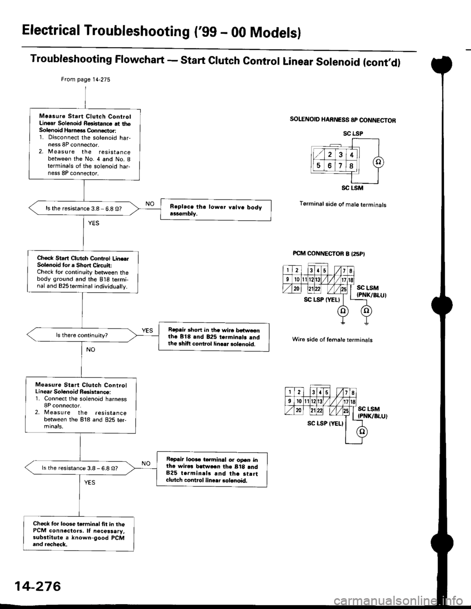
Troubleshooting Flowchart - start clutch control Linear solenoid (cont,d)
Frcm page 14.275
SOLENOID HARNESS 8P CONNECTOR
T6rminal side of male terminals
Wire side of f6male terminals
SC LSM(PNK/BLU)
Measurs Start Clutch ControlLinear Solenoid R€aistance at thsSolenoid Harne€s Connector:1. Disconnect the solenoid har-ness 8P connector.2, M easu re the resistancebetween the No. 4 and No. Iterminals of the solenoid har-ness 8P connector,
ls the resistance 3.8- 6.8 0?
Check Start Clutch Control Line.rSolenoid tor a Short Circuit:Check for continuity between thobody ground and the 818 termi-nal and B2Sterminal individually.
R€p.ir short in th. wire bctw.onth6 818 and 825 termin.lr rndthe 3hift cont ol linc.r solonoid.
Measure Start Clutch ControlLinear Solenoid R6ist.nco:1. Connect the solenoid harness8P conn€clor.2. Measure the resistancebetlveen the 818 and 825 ter,mtnats,
Raprir looa. t€.minal or opan intha wirars lratwe.n the B18 and825 terminal3 and tha st!rtclutch control linoar 3olanoid,
ls the resistance 3.8-6.8 O?
Check to. loose tarminal fit in thoPCM connactors. It necessary,substitute a known-good PCMand recheck.
SC LSP
SC LSM
14-276
Page 955 of 2189
Electrical Troubleshooting ('99 - 00 Models)
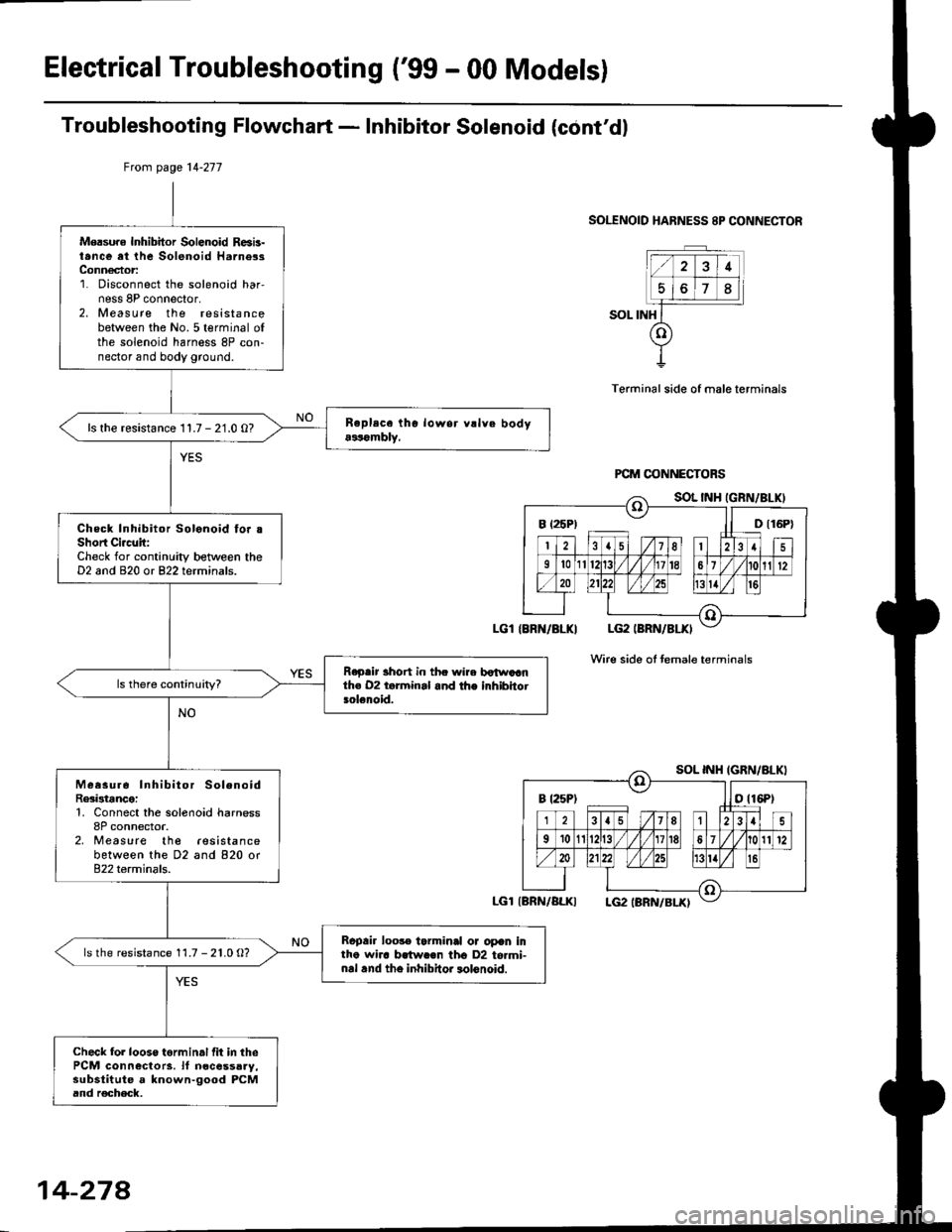
Troubleshooting Flowchart - Inhibitor Solenoid (cont'dl
SOLENOID HARNESS 8P CONNECTOR
SOL INH
Terminal side of male terminals
Wire side oI temale terminals
Mersure Inhibitor Solenoid R6b-t.nce at the Solenoid Harne3sConn€ctor:1. Disconnect the solenoid har,ness 8P connector,2. Measure the resistancebetween the No.5 terminal ofthe solenoid harness 8P con-nector and body ground.
ls the resistance 11.7 - 21.0 O?
Check Inhibitor Solonoid fo. .Short Ci.c!it:Check for continuity between theD2 and 820 or 822 terminals.
R.p.ir 3hort in thc wire botwaanth€ 02 t.rminal and the inhibhotsolenoid.
Measur6 Inhibitor SolenoidRe3istance:1, Connect the solenoid harness8P connector.2, Measure the lesistancebetween the D2 and 820 or822 terminals.
Rcpair loo3. tarminal or opan intho wha brtw.€n tho D2 to.mi-nal .nd tho inhibitor lolonoid.
ls the resistance 11.7 - 21.0 O?
Check fol looso torminal fit in thePCM connectors. lf n€cessaay,substitute a known-good PCMand r€check.
Ftom page 14-277
LGl IBRN/BLKI
LGl{BRN/ALKI
B t25P) ll D t16P)
B t25Pt otl6Pt
14-274
Page 957 of 2189
Electrical Troubleshooting ('gg - 00 Models)
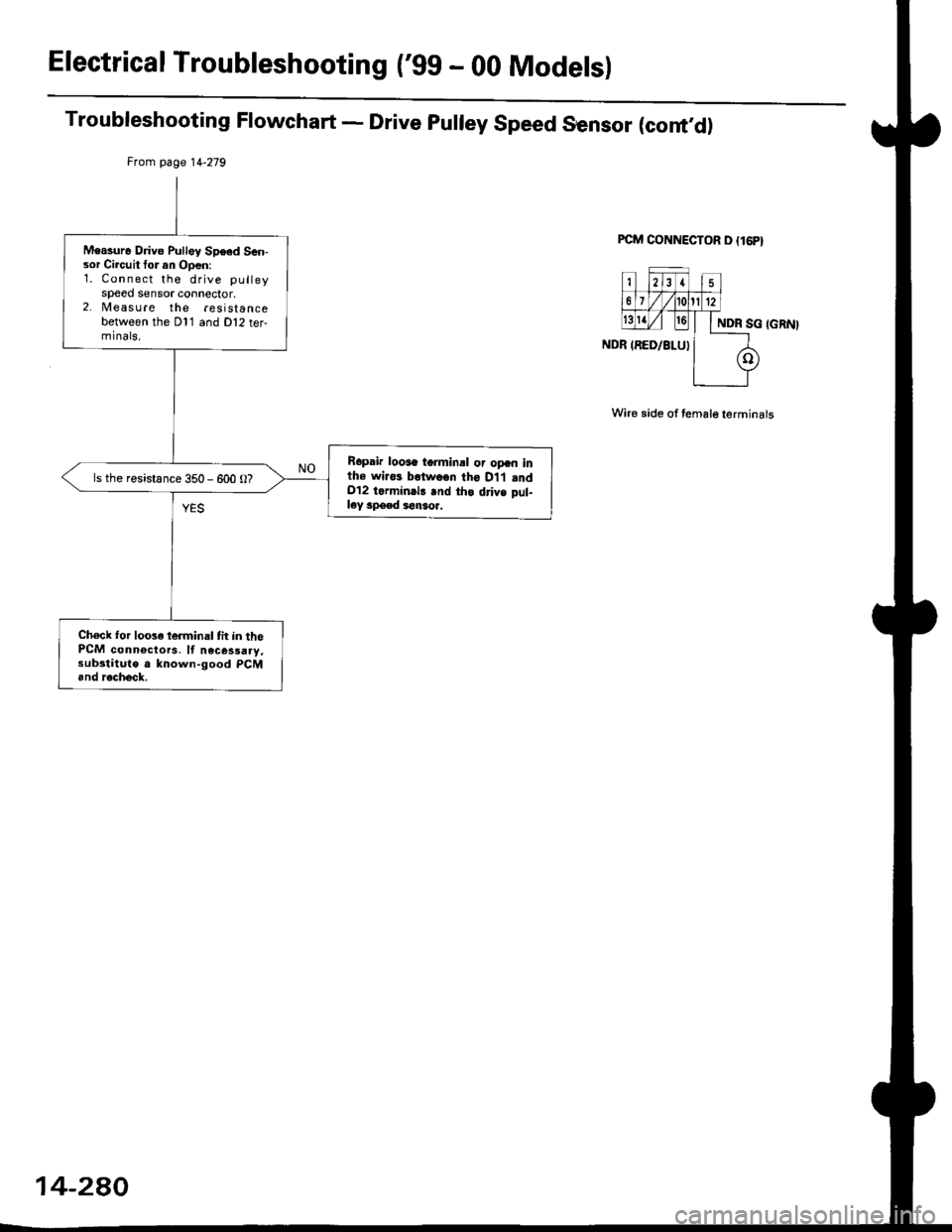
Troubleshooting Flowchart - Drive pulley Speed Sensor (cont,d)
PCM CONNECTOR D {16P}
Wire side of temale terminals
From page 14-279
Measure Drivo Pulley Speed Sen-sor Circuit tor an Open:1. Connect the drive pulleyspeed sensor connector,2. lvleasu re the resistancebetween the Dl1 and Dl2 ter-minals.
R6pair loose tgrminal or opan inthe wiros betwo€n tho D1,l .ndOl2 tarminrl! .nd th. drivs pul-ley speed *n3or.
ls the resistance 350 - 600 O?
Ch6ck for loose lerminal tit in thePCM connectors, ll nece3saay,substituto a known-good PCM6nd r€check.
14-280
Page 959 of 2189
Electrical Troubleshooting ['gg - 00 Models)
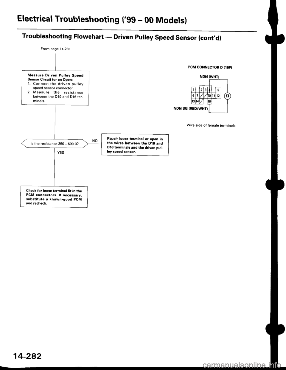
Troubleshooting Flowchart - Driven pulley Speed Sensor (cont,dl
NON SG IRED/WHTI
Wire side of female terminals
From page l4 281
M6asure Driven Pulley SpeedSensor Circuit Ior an Op€n:1. Connect the driven pulleyspeed sensor connector,2, Measure the resistancebetween the D10 and Dl6 ter-minals.
Rgpair loose terminal or open inthe wires botwosn the Dlo and016 torminab rnd the drivon Dul-ley speed 3ensoa,
ls the resistance 350 - 600 O?
Check tor loose terminal tit in thePCM connectors, lf necessary,sub3titute a lnown-good PCMand rech6ck.
14-282