Model HONDA CIVIC 1998 6.G Workshop Manual
[x] Cancel search | Manufacturer: HONDA, Model Year: 1998, Model line: CIVIC, Model: HONDA CIVIC 1998 6.GPages: 2189, PDF Size: 69.39 MB
Page 1062 of 2189
Steering Gearbox
Removal(cont'd)
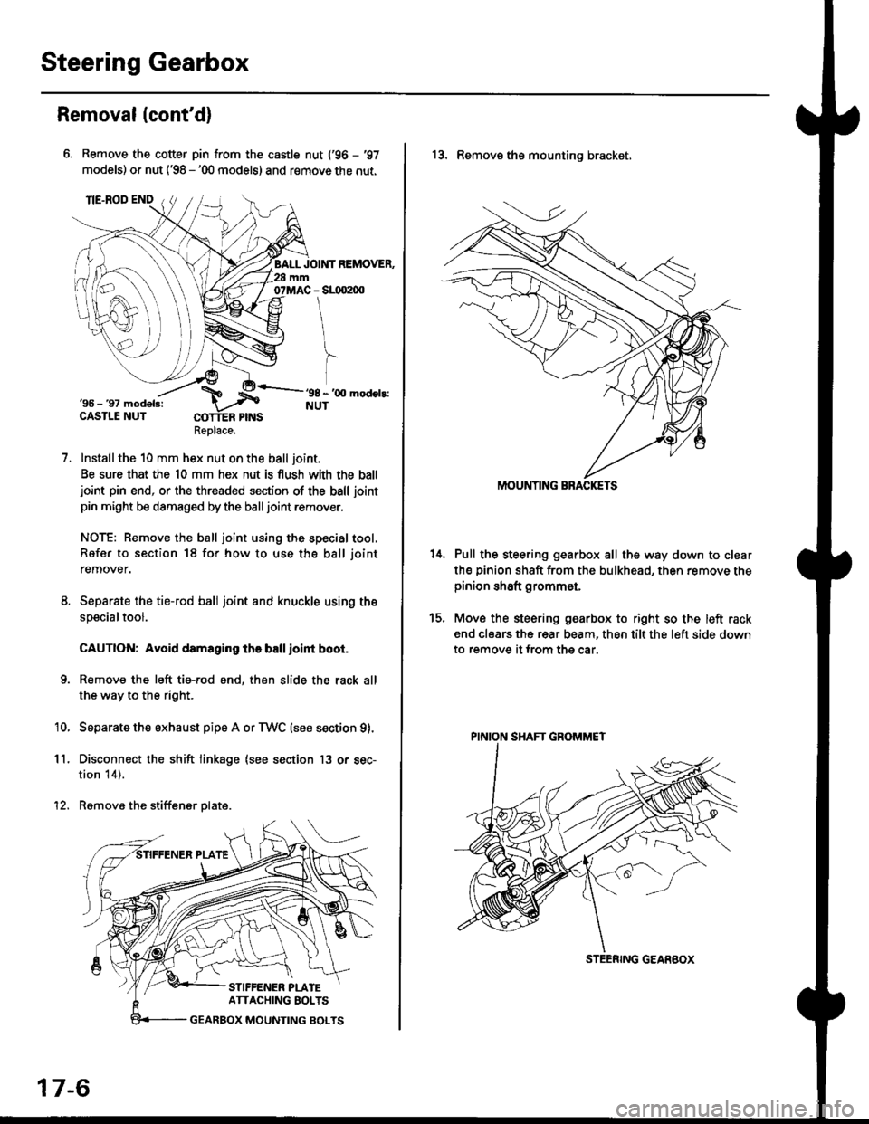
Remove the cotter pin from the castle nut ('96 - '97
models) or nut ('98 - '00 models) and remove the nut.
Installthe 10 mm hex nut on the ball joint.
Be sure that the 10 mm hex nut is flush with the balljoint pin end, or the threaded section of the ball joint
pin might be damaged by the balljoint remover.
NOTE: Remove the ball joint using the special tool,
Refer to section 18 for how to use tho ball joint
remover.
Separate the tie-rod ball joint and knuckle using the
specialtool.
CAUTION: Avoid damaging the ball ioint boot.
Remove the left tie-rod end, then slide the rack all
the way to the right.
Separate the exhaust pipe A or TWC (see section g).
Disconnect the shift linkage (see section 13 or sec-
tion 14).
Remove the stiffener plate.
7.
'10.
11.
12.
Replace.
17-6
13. Remove the mounting bracket,
Pull the steering gearbox all the way down to clear
th€ pinion shaft from the bulkhead, then remove thepinion shaft grommet,
Move the steering gearbox to right so the left rack
end clears the rear beam, then tilt the left side down
to remove it from the car.
t5.
STEENING GEARBOX
PINION SHAFT GROMMET
Page 1070 of 2189
Steering Gearbox
Installation (cont'dl
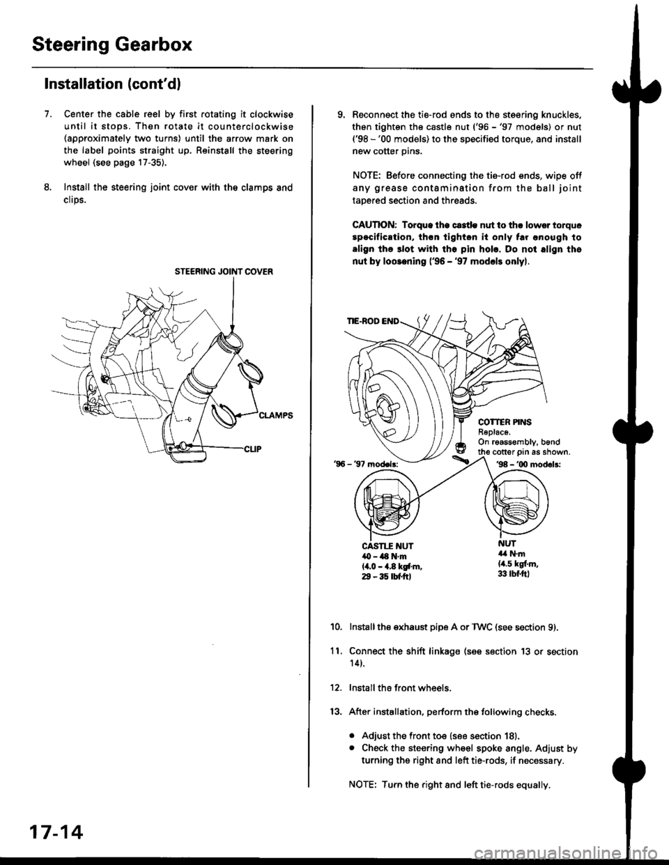
Center the cable reel by first rotating it clockwise
until it stops. Then rotate it counterclockwise(approximately two turns) until the arrow mark on
the label points straight up. Reinstall the steering
wheel (see page 17-35).
Install the steering joint cov€r with the clamps and
clrps.
7.
STEERING JOINI COVER
17-14
9. Reconnsct the ti€-rod ends to the steering knuckles,
thon tightsn th€ castle nut ('96 -'97 models) or nut('98 -'00 models) to the specified torque, and install
new cotter pins.
NOTE: Before connecting the tie-rod ends, wipe off
any grease contamination from the ball joint
tapered section and threads.
CAUTION: Torque lhe ct3tle nut to thr lowsr torque
spocification, th€n tighton it only tar anough to
align the 3lot with tho pin hob. Do not align the
nut by loosening ('96 - '97 modcls onlyl.
TIE.ROD
COTTER PINSR6plac6.On rgassombly, b6nd
'96 - 37 model3:
cotter prn as shown.'98 - '00 modol3:
NUT4a N.m(4.5 kgf.m,33 lbr.ftl
CAST1T NUT,O - ilt N'm{4,0 - 4.8 kgf.m.29 - 35 tbtftl
10.Installthe exhaust pipe A or TWC (see section 9).
Connect the shift linkage (see section 13 or section
14).
Install the front wheels.
After installation, perform the following checks.
. Adjust the front toe (see section 18).. Check the steering wheel spoke angle. Adjust by
turning the right and left tie-rods, if necessary.
NOTE: Turn the right and left tie-rods equally.
ll.
Page 1088 of 2189
Inspection and Adjustment
Pump Belt
NOTE: When using a new belt, first adjust the deflection
or tension to the values for the new belt, then readjust
the deflection or tension to the values for the used beltafter running engine for five minutes.
Inspection
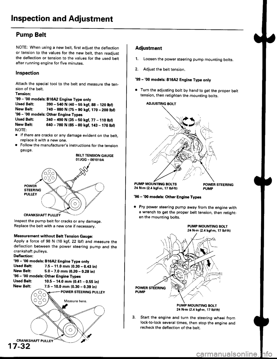
Attach the special tool to the belt and measure the ten-sion of the belt.
Tension:'99 -'00 mod€ls: B1642 Engin. Type onlyUsed Bsh: 390 - 540 N lao - 55 kgt.88 - 120 tbf)New Belt:740 - 880 N {75 - 90 kgf, 170 - 200 tbt}'96 - '00 models: Other Engine Types
Used Beh: 340 - 490 N (35 - 50 kgf, 77 - ilO tbflNew Belt:640 - 780 N 165 - 80 ksf, 1& - 176 tbf)NOTE:
. lf there are cracks or any damage evident on the belt,reDlace it with a new one.. Follow the manufacturer's instructions for the tensiongauge.
BELT TENSION GAUGE07JGG _ 001010A
Inspect the pump belt for cracks or any damage.Replace the belt with a new one if necessary.
Measuremont without Beh Tension Gauga:
Apply a force of 98 N (10 kgt,22 lbfl and measure thedeflection between the power steering pump and thecrankshaft pulleys.
Dsflectior:'99 -'00 model3: 816A2 Engine Typ€ ontyUsed Beh: 7.5 - 11.0 mm t0.30 - 0.43 inlNew Beh:5.0 - 7.0 mm (0.20 - 0.28 in)'96 - '00 models: Othor Engine Typos
Used Behi 10.5 - 14.0 mm (0.ial - 0.59 inlNow Beh:7.5 - 10.0 mm (0.30 - 0.39 inl
POWER STEERING PULUY
CRANKSHAFT PULLEY
17-32
Adiustment
1. Loosen the power steering pump mounting bolts.
2. Adjust the belt tension.
'99 - '00 mod€ls: 816A2 Engin€ Typo only
. Turn the adjusting bolt by hand to get the proper belttension, then retighten the mounting bolts,
ADJUSNNG BOLT
PUMP MOUNNNG BOLTS24 N.m (2.4 kgf'm, 17 tbtftlPOWER STEERINGPUMP
'96 -'00 modek: Othcr Engins Typos
. Pry power steering pump away from the engine witha wrench to get the proper belt tension, then retight-en the mounting bolts.
PUMP MOUNTING BOLT24 N.m (2,4 kgf.m, 17 lbl.ftl
PUMP MOUNTING BOLT24 N.m {2.a kgt m, 17 tbtftl
Start the engine and turn the steering wheel fromlock-to-lock several times, then stop the engine andrecheck the deflection of the belt,
Page 1089 of 2189
IRack Guide Adjustment
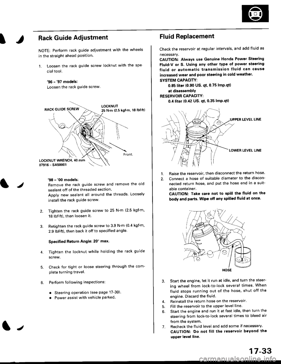
NOTE: Perform rack guide adjustment with the wheels
in the straight ahead Position.
1. Loosen the rack guide screw locknut with the
cialtool.
'96 - '97 models:
Loosen the rack guide screw
'98 - '00 models:
Remove the rack guide screw and remove the old
sealant off of the threaded section.
Apply new sealant all around the threads. Loosely
installthe rack guide screw
Tighten the rack guide screw to 25 N'm (2.5 kgf'm.
18 lbf.ft), then loosen it.
Retighten the rack guide screw to 3 9 N'm (0.4 kgim,
2.9 lbf.ft), then back it off to specified angle.
Specified Return Angle: 20" max.
Tighten the locknut while holding the rack guide
screw.
Check for tight or loose steering through the com-
plete turning travel.
Perform following insPections:
. Steering operation (see page 17-30).
. Power assist with vehicle parked.
4.
LOCKNUT WRENCH, 40 mm
lr
17-33
Fluid Replacement
Check the reservoir at regular intervals, and add fluid as
necessary.
CAUTION: Always us€ Genuine Honda Power Stearing
Fluid-V or S. Using any other type of power sto€ring
tluid or automatic transmission lluid can cause
increased wear and poor steering in cold weathor.
SYSTEM CAPACITY:
0.85 liter 10.90 US' qt,0.75 lmp'qt)
at disassembly
RESERVOIR CAPACITY:
0.4 liter (0.42 US. qt, 0.35 lmP.qt)
LEVEL LINE
LOWER LEVEL LINE
1. Raise the reservoir, then disconnect the return nose.
2. Connect a hose of suitable diameter to the discon-
nected return hose, and put the hose end in a suit-
able container.
CAUTION: Take care not to spill tho fluid on the
body and parts. Wipe off any spill€d fluid at oncs'
3. Start the engine, let it run at idle, and turn the steer-
ing wheel from lock-to-lock several times When
fluid stops running out of the hose, shut off the
engine, Discard the fluid.
4. Reinstall the return hose on the reservoir'
5. Fill the reservoir to the upper level line.
6. Start the engine and run it at fast idle, then turn the
steering trom lock-to-lock several times to bleed air
trom the system.
7. Recheck the fluid level and add some it necessary.
CAUTION: Do not fill the reservoir beYond the
upper l€vel line.
HOSE
Page 1096 of 2189
Power Steering Pump
RemovaUlnstallation
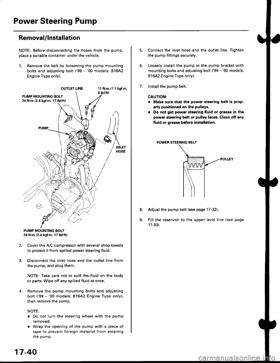
NOTE: Eefore disconnecting the hoses from the pump,
Dlace a suitable container under the vehicle.
1. Remove the belt by loosening the pump mounting
bolts and adjusting bolt ('99 -'00 models: 81642
Engine Type only).
OUTLET LINE11 N.m {1.1 kgf'm,8
L
PUMP MOUNTING BOLT24 N.m (2.4 kgl.m, 17 lbf ft)
2. Cover the Ay'C compressor with several shop towels
to protect it from spilled power steering fluid.
3. Disconnect the inlet hose and the outlet line from
the pump, and plug them.
NOTE: Take care not to spill the fluid on the body
or parts, Wipe off any spilled fluid at once.
4. Remove the pump mounting bolts and adjusting
bolt ('99 -'00 models: 816A2 Engine Type only),
then remove the pump.
NOTE:
. Do not turn the steering wheel with the pump
removeo.
. Wrap the opening of the pump with a piece of
tape to prevent foreign material from entering
the pump.
17-40
1.
8.
Connect the inlet hose and the outlet line. Tiqhten
the pump fittings securely.
Loosely install the pump in the pump bracket with
mounting bolts and adjusting bolt ('99 -'00 models:
81642 Engine Type only).
Installthe pump belt.
CAUTION:
. Make sure that the power steering belt is prop-
orly positioned on the pulleys.
. Do not get power stoering tluid or grease in the
power steering bsh or pulley faces. Clean off any
fluid or grease before installrtion.
Adjust the pump belt (see page 17-32).
Fill the reservoir to the upper level line (see page
Page 1103 of 2189
Steering Gearbox
)
Removal
NOTE: Using solvent and a brush, wash any oil and dirt
off the valve body unit its lines. and the end if the gear-
box. Blow dry with comPressed air.
1. Drain the power steering fluid as described on page
2. Raise the front of vehicle, and support it on safety
stands in the proper locations (see section 11.
3, Remove the front wheels.
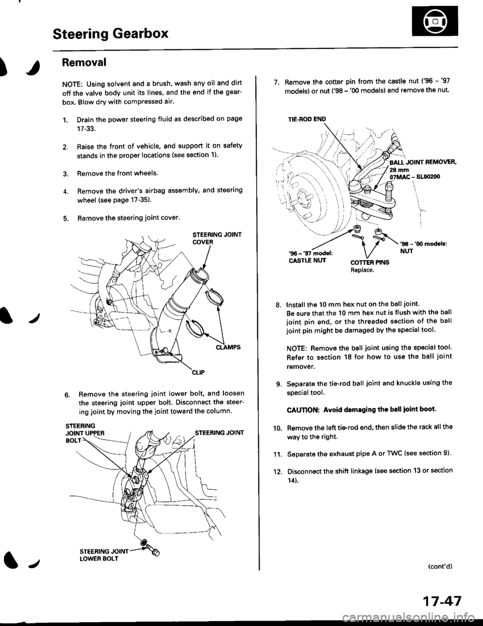
4. Remove the driver's airbag assembly, and steering
wheel (see page 17-35)
5. Bemove the steering joint cover.
6. Remove the steering joint lower bolt, and loosen
the steering joint upper bolt. Disconnect the steer-
ing joint by moving the ioint toward the column
tJ
17-47
TIE.ROD END
7. Remove the cotter pin from the castle nut {'96 -'97
models) or nut ('98 - '00 modslsl and remove the nut.
BALL JOINT REMOVER.28 mm07MAC - SLqI2|X)
'98 - '00 mod.b:NUT
8.
COTTER PINSRepl6ce.
lnstall the t0 mm hex nut on the ball joint.
Be sure that the 10 mm hex nut is flush with the ball
joint pin end, or the threaded section of the ball
joint pin might be damaged by the special tool.
NOTE: Remove the ball joint using the special tool.
Refer to section 18 for how to use ths ball joint
remover.
Seoarate the tie-rod ball joint and knuckle using the
specialtool.
CAUnON: Avoid damaging tho ball ioint boot.
Remove the left tie-rod end, then slide the rack all the
way to the right.
Separate the exhaust pipe A or TWC (see section 9).
Disconnect the shift linkage (see section 13 or section
14).
(cont'd)
9.
10.
11.
12.
Page 1105 of 2189
)
Disassembly
t)
Steering Rack DisassemblY
NOTE:
r Before disassemble the gearbox, wash it off with sol
vent and a brush.
. Do not dip seals and O-rings in solvent.
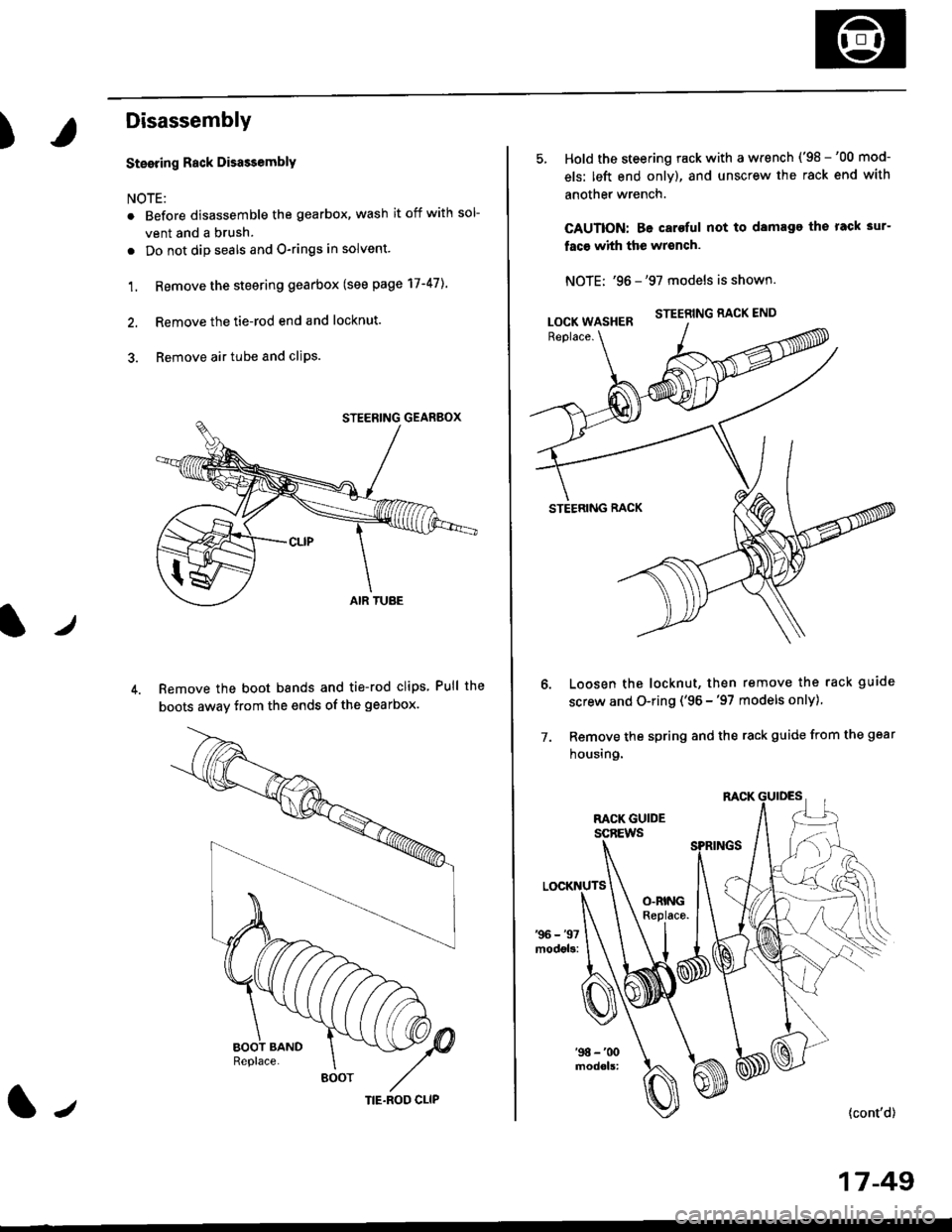
1. Remove the steering gearbox (see page 17-47]..
2. Remove the tie-rod end and locknut.
3. Remove air tube and cliPs.
Remove the boot bands and tie-rod clips Pull the
boots away from the ends of the gearbox.
BOOT
(|-,TIE.ROD CLIP
Hold the steering rack with a wrench ('98 -'00 mod-
els: left end only), and unscrew the rack end with
another wrench.
CAUTION: Be caroful not to damage the rack 3ur-
faco whh the wrench.
NOTE: '96 -'97 models is shown.
STEERING RACK END
STEERING RACK
Loosen the locknut, then remove the rack guide
screw and O-ring ('96 -'97 models only)
Remove the spring and the rack guide from the gear
housing.
7.
{cont'd}
17 -49
LOCK WASHER
Page 1110 of 2189
Steering Gearbox
Disassembly (cont'd)
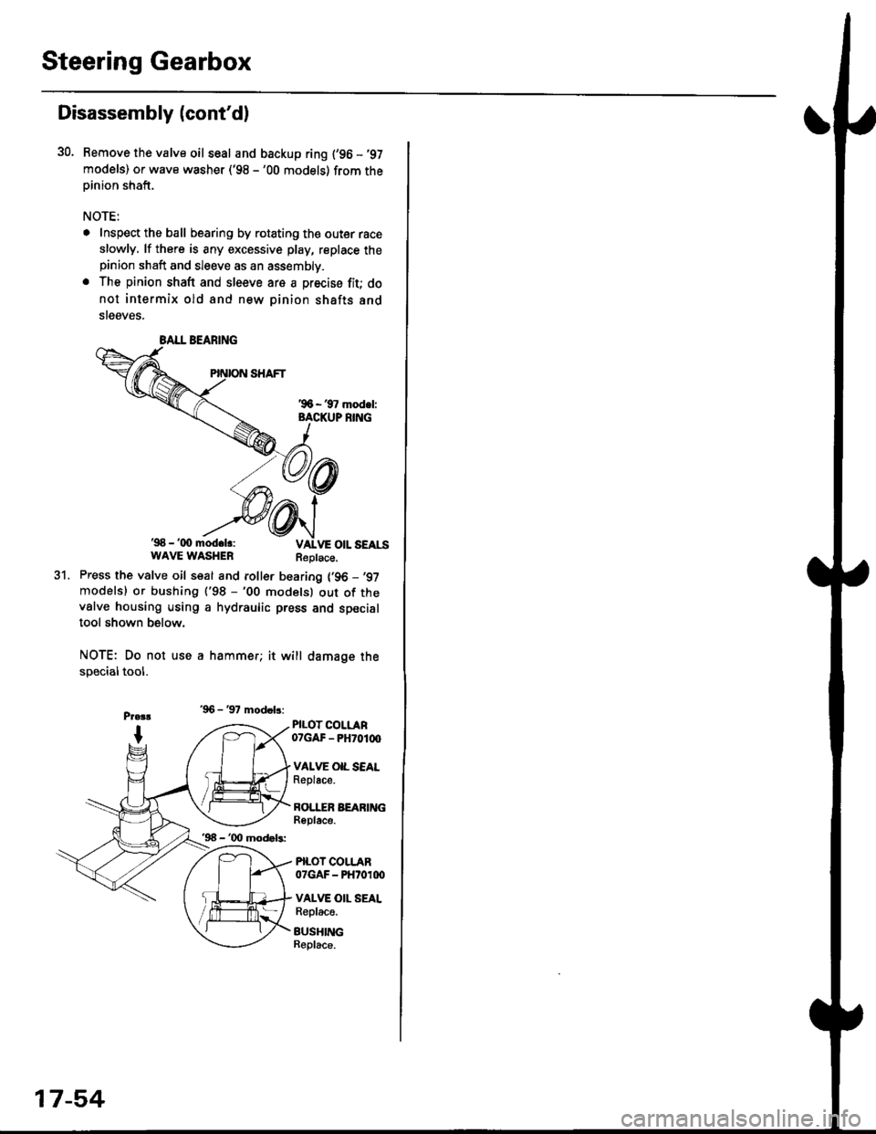
30. Bemove the valve oil seal and backup ring {'96 -'97
models) or wave washer ('98 -'00 models) from theoinion shaft.
NOTE:
. Inspect the ball bearing by rotating the outer race
slowly. lf there is any excessive play, replace thepinion shaft and sleeve as an assembly.
. The pinion shaft and sleeve are a precise fit; do
not intermix old and new pinion shafts and
steeves.
'98 - '(x) mod.lr:WAVE WASHERReplace.
31.Press the valve oil seal and roller bearing {'96 -,97
modelsl or bushing ('98 -'00 modelsl out of thevalve housing using a hydraulic press and specialtool shown below.
NOTE: Do not use a hammer; it will damage the
specialtool.
'96 - '97 modob:
PILOT COLLAR07GAF - PH70100
VAI.VE OIL SEALReplace.
BOI.I"ER BEARINGReplace.
PILOT COLLAR07GAF - PHtoroo
VALVE OII. SEALReplace.
BUSHINGBeplace.
BALL BEARING
'96 - '00 mod.b:
17-54
Page 1111 of 2189
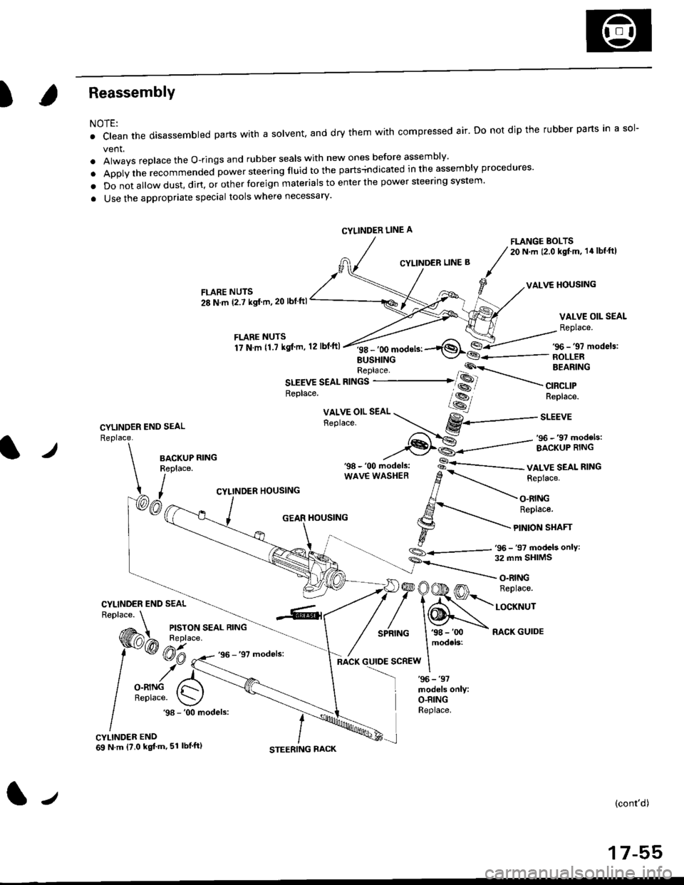
)Reassembly
NOTE:
. clean the disassembled parts wrth a solvent, and dry them with compressed air. Do not dip the rubber parts in a sol-
vent.
. Always replace the O-rings and rubber seals with new ones before assembly'
. Apply the recommended power steering fluid to the parts+ndicated in the assembly procedures'
o Do not a||ow dust, dirt, or other foreign materials to enter the power steering system.
a Use the appropriate special tools where necessary'
FLANGE BOLTS20 N.m (2.0 kgt'm, 14lbf ftl
CYLINDER LINE B
VALVE HOUSINGFLARE NUTS
28 N.m (2.7 ksf m,20 lbf ftl
VALVE OIL SEAL
Replace.
CYLINDER END SEAL
Replace.
f itllTllli".",'r'o,.n,ft
''*^'*-1$*€-/s6-,,mode,3:
EUSHINGReplace 'P'\-- BEARING
SLEEVE SEAL RINGS ..-------......�� SS
.----
",a"a,,
*---
--,
Replace. lss-, Replace.
Xll,Y5"l'.
"o. --r...- gY------..r.u,
,-f-..-S: _ ,96 _,9? models:
--€l€--------=- ircriip'ii.rt'-l./BACKUPReplace.
I,
wAvE wAsHER d
-.-.-r_ i"pru"".
CYLINDER HOUSING // -\-
, AJ - O.RING
/ ,S-'..- ReDtace.
_ j GEAR HouslNG l.g --'\-
\- t F
tonsrnrr
.,_- s
- 'oo ,,iod"t., -s-'--------- vALvE SEAL R'NG
S_.<---,tj- 97 models onlY:
CYLINDER END SEAL
)@OOD m n"prac".
/'\N,."._nrNG I '98 - 'oo - RACK GUIDE
models:
:scREw I
O.RINGReplace..98 - '00 models:
CYLINDER END69 N.m {?.0 kgt'm,51 lbl'ft)
(cont'd)
17-55
CYLINDER LINE A
tJ
Page 1112 of 2189
Steering Gearbox
Reassembly (cont'd)
Valve Body Unit Reassembly
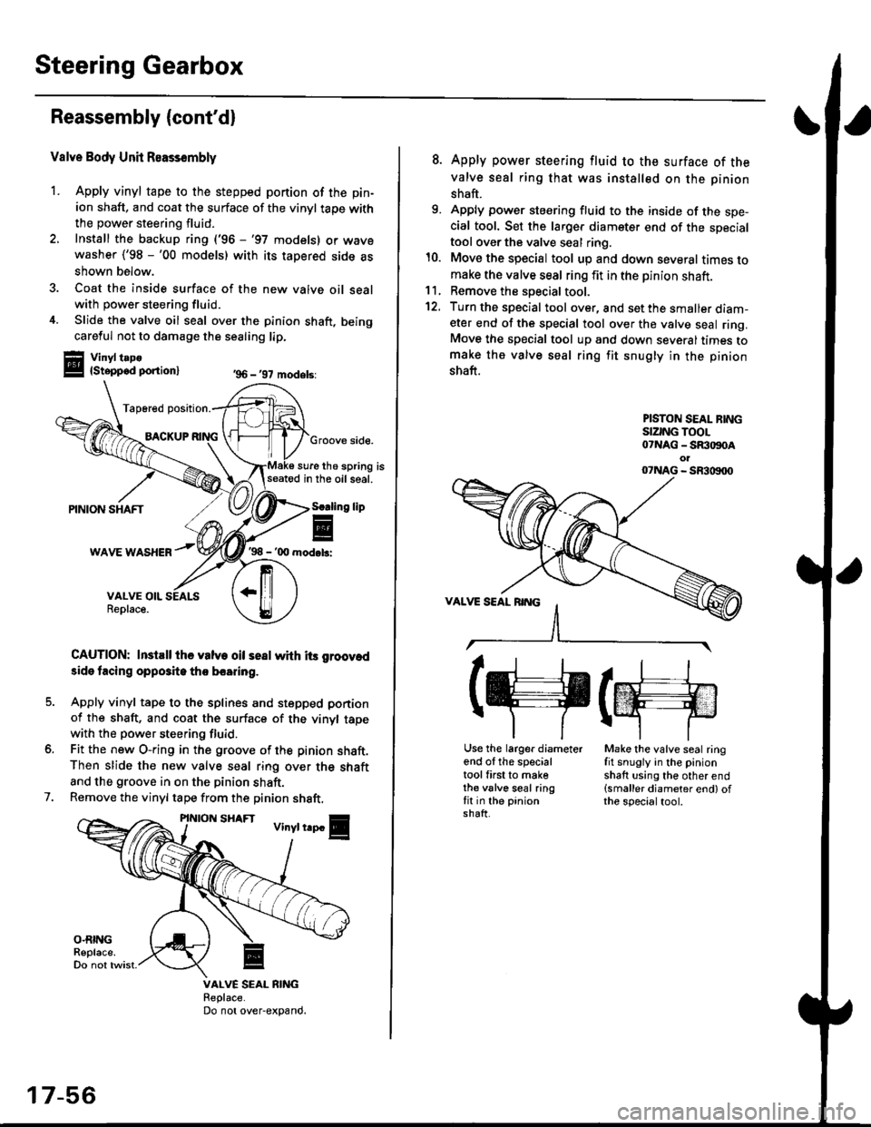
1. Apply vinyl tape to the stepped portion of the pin-
ion shaft, and coat the surface of the vinyl taoe with
the power steering fluid.
2. Install the backup ring ('96 -'97 models) or wavewasher ('98 -'00 models) with its tapered side as
shown below.
3. Coat the inside surface of the new valve oil sealwith power steering fluid.
4. Slide the valve oil seal over the pinion shaft, being
careful not to damage the sealing lip.
Vinyl t.po{Stepped ponion}
Tap6red position.
BACKUPGroove side.
sure the spring isseatod in the oil seal.
'98 - '00 mod.b:
CAUTION: InstEll ihe valve oil seal whh its groov.d
3ide tacing opposite tho boaring.
Apply vinyl tape to the splines and stepped portion
of the shaft, and coat the surface of the vinyl tapewith the power steering fluid.
Fit the new O-ring in the groove of the pinion shaft.Then slide the new valve seal ring over the shaft
and the groove in on the pinion shaft.
Remove the vinyl tape from the pinion shaft,
'96 - '97 models:
lip
7.
VALVE SEAL RIiIGReplace.Do not over-expand.
17-56
8. Apply power steering fluid to the surface of the
valve seal ring that was installed on the pinion
shaft.
9. Apply power steering fluid to the inside of the spe-cial tool. Set the larger diameter end of the specialtool over the valve seal ring.
10. Move the special tool up and down several times tomake the valve seal ring fit in the pinion shaft.11, Remove the soecial tool.
12. Turn the special tool over, and set the smaller diam-eter end of the special tool over the valve seal ring.Move the special tool up and down several times tomake the valve seal ring fit snugly in the pinion
shaft.
PISTON SEAL BINGSIZING TOOL07NAG - SR:togoAol07NAG - SR3|X)00
(g(m
Use the larger diameterend of the specialtool first to makethe valve seal ringfit in the pinionshaft.
Make the valve seal ringfit snugly in the pinionshaft using the other end(smaller diameter end) ofthe specialtool.