vehicle speed sensor HONDA CIVIC 1998 6.G Owner's Manual
[x] Cancel search | Manufacturer: HONDA, Model Year: 1998, Model line: CIVIC, Model: HONDA CIVIC 1998 6.GPages: 2189, PDF Size: 69.39 MB
Page 771 of 2189
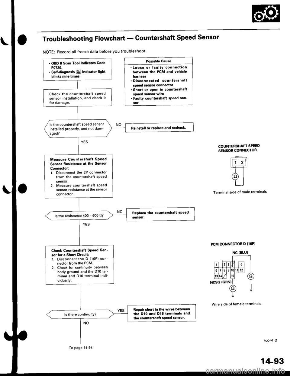
Troubleshooting Flowchart - Countershaft Speed Sensor
NOTE: Record all freeze data before you troubleshoot
Po$iblo Cause
. Loos€ or fsulty conneclionbetween the PCM and vehicle
hainoss' Disconnectod countersh.ft
spoed senaof connoctor. Short or opgn in counteBhaft
3Deed aensor wire. Faulty counloEhaft 3p€ed sen'
soa
COUNTERSHAFf SPEED
SENSOR CONNESTOR
Terminal side oI male terminals
FCM CONNECTOR D I16PI
rconl c
1+93
NC IBLUI
. OBD ll Scan Tool indicat6 Code
PO720.. Self-diagnosis E indicator light
blinks nin6times.
Check the countershaft sPeed
sensor installation, and check it
lor damage.
ls the countershaft speed sensor
installed properly, and not dam-
aged?
Reinstall or replace and rechock.
Measurg Counlershatt SPeed
Sgn3ol R6istance at tho Son3ol
Connector:1. Disconnect the 2P connector
from the countershaft sPeed
sensor.2, Measuro countershaft sPeed
sensor resistanca at the sensor
connector.
ls the resistance 400 - 600 O?
Chcck CounteEh.tt SPeed Sen'
sor lor a Short Circuit:1. Disconnect the D {16P) con
nector trom the PCM.2. Check lor continuity between
body ground and the D10 ter_
minal and D16 terminal indi-
vid!ally.
R6oai. short in tl|€ wi.6a bstwa€n
the D10 and D16 t.rminali end
tho countdthatt rP€od senaor.
To page 14 94
Wire side of temale terminals
Page 791 of 2189
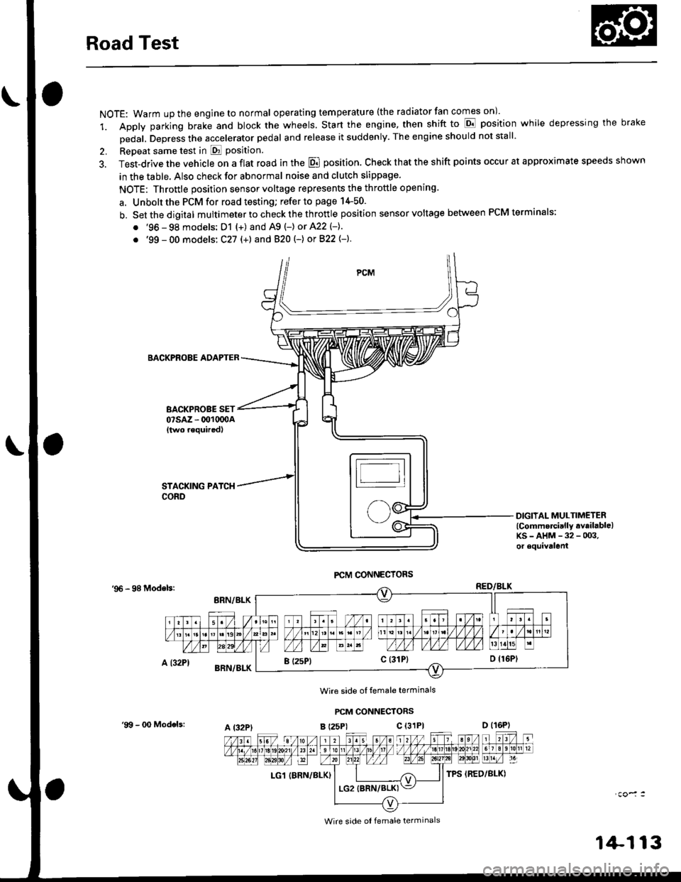
Road Test
NOTE: Warm up the engine to normal operating tem peratu re (the rad iator fan comes on )'
1. Apply parking brake and block the wheels. Start the engine, then shift to E position while depressing the brake
Dedal, Depress the accelerator pedal and release it suddenly. The engine should not stall'
2. Repeat same test in E Position.
3. Test-drive the vehicle on a flat road in the E position. Check that the shift points occur at approximate speeds shown
in the table. Also check for abnormal noise and clutch slippage.
NOTE: Throttle position sensor voltage represents the throttle opening
a. Unbolt the PCM for road testing; refer to page 14-50.
b. Setthedigital multimeter to check the th rottle position sensor voltage between PCM terminals;
. '96 - 98 models: D1 {+) and A9 (-) or 422 (-}.
. '99 - 00 models: C27 (+) andB20t-) orB22{-}.
BACKPROBE ADAPTER
BACKPROBE SET07sAz - 001oq)A{two requiredl
DIGIIAL MULTIMETERlCommercially available)KS-AHM-32-003,or equivalenl
'96 - 98 Modelsr
Wire side ol temale terminals
PCM CONNECTORS
B t25Pl c (31P)
LG1 IBRN/BLK)
I (25P1c (31P}
A t32PtD (16P)
Wire side ol female terminals
'9!t - 00 Models:
1+113
Page 800 of 2189
Transmission
Removal
@Maks sure lifts, iacks and safety stands are placedproperly, and hoist bracket ate aftached to the cor_rec{ position on the engine lsee section 1).Apply parking brake and block rear whoels so vehiclewill not roll off stands and fall on you while workingunder it.
CAUTION: Use tender covers to avoid damaging paint-ed surfaces.
1, Disconnect the battery negative (_) terminal fromthe battery, then remove the positive (+) terminal.
2. Remove the intake air duct.
D16Y7 engins:
Remove the intake air duct and resonator.
D16Y8 engine:
Remove the intake air duct and the air cleaner hous-ing assembly,
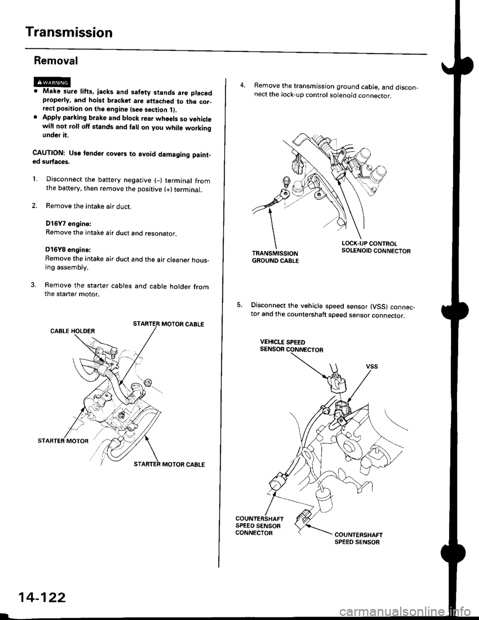
3. Remove the starter cables and cable holder fromthe starter motor.
MOTOR CABLE
MOTOR CABLE
14-122
4. Remove the transmission ground cable, and discon_nect the lock-up control solenoid connector.
LOCK.UP CONTROLSOLENOID CONNECTOR
5, Disconnect the vehicle speed sensor (VSS) connec_tor and the countershaft speed sensor connector.
VEHICLE SPEED
Page 873 of 2189
Description
The Continuously Variable Transmission (CVT) is an electronically controlled automatic transmission with drive and driv
en Oullevs, and a steel belt. The CVT provides non stage speeds forward and one reverse. The entire unit is positioned in
line with the engine.
Transmission
Around the outside of the flywheel is a ring gear which meshes with the starter pinion when the engine is being staned.
The transmission has four parallel shafts: the input shaft, the drive pulley shaft. the driven pulley shaft, and the secondary
gear shaft. The input shaft is in line with the engine crankshaft. The drive pulley shaft and the driven pulley shaft consist of
movable and fixed face pulleys. Both pulleys are linked by the steel belt.
The input shaft includes the sun gear. The drive pulley shaft includes the forward clutch which mounts the carrier assem-
bly on the forward clutch drum. The carrier assembly includes the pinion gears which mesh with the sun gear and the ring
gear. The ring gear has a hub-mounted reverse brake disc.
The driven pulley shaft includes the start clutch and the secondary drive gear which is integral with the park gear' The sec-
ondary gear shaft is positioned between the secondary drive gear and the final driven gear. The secondary gear shaft
includes the secondary driven gear which serves to change the rotation direction. because the drive pulley shaft and the
driven oullev shaft rotate the same direction. When certain combinations of planetary gears in the transmission are
engaged by the clutches and the reverse brake, power is transmitted from the drive pulley shaft to the driven pulley shaft
to provide E, E, E, and El.
Electronic Control'96 - 98 Models:
The electronic control system consists of the Transmission Control Module (TCM), sensors, three linear solenoids, and a
inhibitor solenoid. Shifting is electronically controlled under all conditions'
The TCM is located below the dashboard, behind the kick panel on the driver's side.'99 - 00 Models:
The electronic control svstem consists of a Powertrain Control Module (PCM), sensors, three linear solenoids and an
inhibitor solenoid. Shifting is electronically controlled under all conditions. A Grade Logic Control System to control shift-
ing in E position while the vehicle is ascending or descending a slope.
The PCM is located below the dashboard, under the kick panel on the passenger's side.
Hydraulic Control
The lower valve body assembly includes the main valve body, the Pressure Low (PL) reguiator valve body, the shift valve
body, the start clutch control valve body, and the secondary valve body. They are positioned on the lower part of the
transmission housing.
The main valve body contains the Pressure High (PH) control valve, the lubrication valve, and the pitot regulator valve.
The secondary valve body contains the PH regulator valve, the clutch reducing valve, the start clutch valve accumulator,
and the shift inhibitor valve. The PL regulator valve body contains the PL regulator valve and the PH-PL control valve
which is ioined to the PH,PL control linear solenoid. The inhibitor solenoid valve is bolted on the PL regulator valve body.
The shift valve body contains the shift valve and the shift control valve. which is joined to the shift control linear solenoid.
The start clutch control valve body contains the start clutch control valve, which is joined to the start clutch control linear
solenoid. The linear solenoids and the inhibitor solenoid are controlled by the TCM or PCM. The manual valve body which
contains the manual valve and the reverse inhibitor valve, is bolted on the intermediate housing.
The ATF pump assembly is located on the transmission housing, and is linked with the input shaft by the sprockets and
the sprocket chain. The pulleys and the clutch receive fluid from their respective feed pipes, and the reverse brake receives
fluid from internal hydraulic circuit.
Shift Control Mechanism
Input from various sensors located throughout the vehicle determines which linear solenoid the TCM or PCM will activate.
Activating the shift control linear solenoid changes the shift control valve pressure, causing the shift valve to move. This
pressurizes the drive pulley pressure to the drive pulley and the driven pulley pressure to the driven pulley and changes
their effective pulley ratio. Activating the start clutch control linear solenoid moves the start clutch control valve. The start
clutch control valve uncovers the port, providing pressure to the start clutch to engage it(cont'd)
14-195
,!
Page 881 of 2189
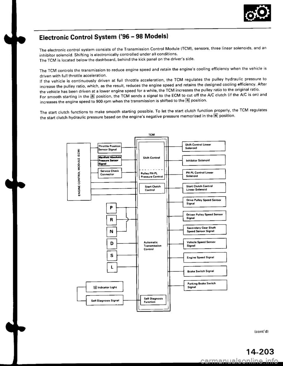
Electronic Control System ('96 - 98 Modelsl
The electronic control system consists of the Transmission control Module (TcM), sensors, three linear solenoids, and an
inhibitor solenoid. Shifting is electronically controlled under all conditions
The TCIM is located below the dashboard, behind the kick panel on the driver's side'
The TcN4 controls the transmission to reduce engine speed and retain the engine's cooling efficiency when the vehicle is
driven with Iull throttle acceleration
lf the vehicle is continuously driven at full throttle acceleration, the TCM regulates the pulley hydraulic pressure to
increase the pulley ratio, which, as the result. reduces the engine speed and retains the designed cooling efficiency After
the vehicle has been driven at a lower engine speed for a while, the TCM increases the pulley ratio to the original ratio.
For smooth starting in the E position, the TcM sends a signal to the EcM to cut off the rvc clutch {if the A!/c is on) and
increases the engine speed to 900 rpm when the transmission is shifted to the E position'
The start clutch functions to make smooth starting possible. To let the start clutch function properly. the TCM regulates
the start clutch hydraulic pressure based on the entine's negative pressure memorized in the E position'
:
:
z
z
z
S*ond.ry G..r Sh:ft
(cont'd)
14-203
Page 883 of 2189
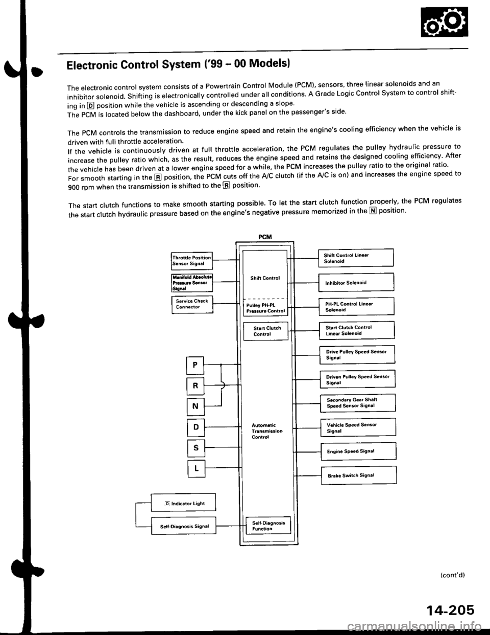
Electronic Gontrol System ('99 - 00 Modelsl
The electronic controt system conststs of a Powertrain control Module (PCM). sensors, three linear solenoids and an
inhibitor solenoid. shifting is electronically controlled under all conditions A Grade Logic control system to control shift-
ing in E position while the vehicle is ascending or descending a slope'
fn"pCVirlocatedbelowthedashboard,underthekickpanelonthepassenger'sside'
The pCM controls the transmassion to reduce engine speed and retain the engine's cooling efficiency when the vehicle is
driven with full throftle acceleration
lf the vehicle is continuously driven at lull throttle acceleration, the PCM regulates the pulley hydraulic pressure to
increase the pulley ratio which. as the result, reduces the engine speed and retains the designed cooling efficiency After
the vehicle has been driven at a lower engine speed for a while, the PCM increases the pulley ratio to the original ratio'
i"i ".nl",rr starting in the E position, the PcM cuts off the ,Vc clutch (if the A/c is on) and increases the engine speed to
900 rpm when the transmission is shifted to the E position'
The start clutch functions to make smooth starting possible. To let the start clutch function properly, the PcM regulates
the start clutch hydraulic pressure based on the engine's negative pressure memorized in the E position'
FCM
s*o.d.ry G..t Sh.h
(cont'd)
14-205
Page 884 of 2189
Description
Electronic Control System ('99 - 00 Modelsl (cont'dl
Grade Logic Control System
How it works:
The PcM compares actual driving conditions with memorized driving conditions. based on the input from the vehiclespeed sensor, the throttle position sensor, the manifold absolute pressure sensor, the engine coolant temperature sensor,the brake switch signal, and the shift lever position signal, to control shifting while the vehicle is ascending or descendinga slope.
Ascending Control
When the PCM determines that the vehicle is climbing a hill in E position, the system selects the most suitable shiftschedule (pulley ratio) according to the magnitude of a gradient. so the vehicle can run smooth and have more powerwhen needed. There are three ascending modes with different shift schedules according to the magnitude ot a gradient inthe PCM.
Descending Control
when the PCM determines that the vehicle is going down a hill in E position. the system selects the most suitable shiftschedule (pulley ratio) according to the magnitude of a gradient. This, in combinstion with engine braking, achievessmooth driving when the vehicle is descending, There are three descending modes with different shift schedules accord-ing to the magnitude of a gradient in the PCM.
L
14-206
Page 901 of 2189
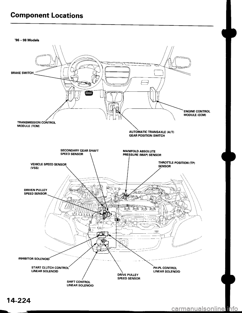
Component Locations
36 - 98 Models
BRAKE SWITCH
DRIVEN PULLEYSPEED SENSOR
INHIBITOR SOLENOID
ENGINE CONTROLMODULE IECMI
SECONDARY GEAR SHAFTSPEEO SENSOR
AUTOMATIC TRANSAXLE (A/T}GEAR POSITION SWITCI{
MANIFOLD ABSOLUTE
VEHICLE SPEEO SENSOR{vss}
IMAPI SENSOR
THROTTI.I POSITION {TPISENSOR
PH.PL CONTROLLINEAR SOLENOID
/i/ i,' / ,','4
,i/:1
t"--.---.- i,,
-_,-:-_a.--:
il
START CLUTCH CONTROLLINEAR SOLENOIDPULLEY
SHIFT CONTROLLINEAR SOLENOTD
$r,
14-224
h
SPEED SENSOR
Page 902 of 2189
![HONDA CIVIC 1998 6.G Owners Manual 99 - 00 Models
CONTROL
AUTOMATIC TRANSAXLE IA/TI
GEAR POS]TION SW]TCH
MANIFOLD ABSOLUTESECONDANY GEAR SHAFT
SPEED SENSORIMAPI SENSOR
VEHICLE SPEED SENSOR
tvss)
THROTTLE POS]TION ITP)SENSOR
PH.PL CONT HONDA CIVIC 1998 6.G Owners Manual 99 - 00 Models
CONTROL
AUTOMATIC TRANSAXLE IA/TI
GEAR POS]TION SW]TCH
MANIFOLD ABSOLUTESECONDANY GEAR SHAFT
SPEED SENSORIMAPI SENSOR
VEHICLE SPEED SENSOR
tvss)
THROTTLE POS]TION ITP)SENSOR
PH.PL CONT](/img/13/6068/w960_6068-901.png)
'99 - 00 Models
CONTROL
AUTOMATIC TRANSAXLE IA/TI
GEAR POS]TION SW]TCH
MANIFOLD ABSOLUTESECONDANY GEAR SHAFT
SPEED SENSORIMAPI SENSOR
VEHICLE SPEED SENSOR
tvss)
THROTTLE POS]TION ITP)SENSOR
PH.PL CONTBOLLINEAB SOLENOIO
DNVEN PUL]-EY
SPEED SENSOR
START CLUTCH CONTROL
PULLEY
SHIFT CONTROLLINEAR SOLENOIO
LINEAR SOIENOID
SPEED SENSOR
14-225
Page 906 of 2189
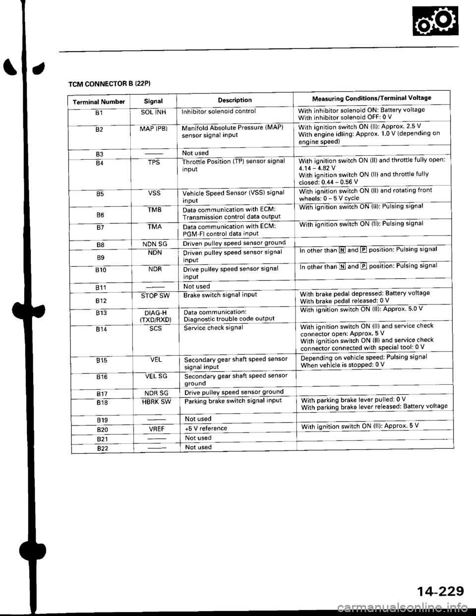
TCM CONNECTOR B (22P}
Terminal NumbelSignalDescriptionMeasuring Conditions/Terminal Voltage
B1SOL INHInhibitor solenoid controlWith inhibitor solenoid ON: Baftery voltage
With inhibitor solenoid OFF: 0 V
82MAP (PB)-M an if old Absol r-rte Pressure IMAP)
sensor signal inPUtWith iqnition switch ON (ll): Approx.2.5 V
With e;gine adling: Approx. 1.0 V (depending on
engine speed)
B3Not used
B4TPS-Throttle Position (TP) sensor signal
input
With ignition switch ON (ll) and throftle fully open:
4.14 - 4.42 VWith ignition switch ON (ll) and throttle fully
closed: 0.44 - 0.56 V
VSSVehicle Speed Sensor (VSS) signal
Inpur
With ignition switch ON (ll) and rotating front
wheelsr 0-5Vcycle
TMBData communication with ECM:
Transmission control data outpUt
With ignilion swltch UN lll): rulslng slgnar
81TMAData communication with EClvl:
PGM Fl control data inPut
With ignition swltch uN {ll,: l-ulslng slgnal
B8NDN SGDriven pulley speed sensor ground
B9NDNDriven pulley speed sensor signal
input
ln other thTnE and E position: Pulsing signal
810NDRDrive pulley speed sensor signal
Input
-tn ottrer ttran E ana E position: Pulsing signal
811Not used
812STOP SWBrake switch signal inPutWith brake pedal depressed: Battery voltage
With brake pedal released: 0 V
813DIAG-H(TXD/RXD)Data communication:Diagnostic trouble code outPut
Wittr ignitio.r s*itct' ON (ll): Approx 5.0 V
814Se-ice ctrect signatWith ignition switch ON (ll) and service check
connector oPen: APProx.5 V
With iqnition switch ON (ll) and service check
"onn"itot. connect"d with special tool: 0 V
Secondary gear shaft speed sensor
signal input
Depending on vehicle speed: Pulsing signal
When vehicle is stoPped: 0 V815VEL
816VEL SGSecondary gear shaft speed sensorgrouno
817NDR SGDrive pulley speed sensor ground
818HBRK SWParking brake switch signal inPutWith parking brake lever pulledr 0 V
With parking brake lever released: Battery voltage
819Not used
B�20VREF+5 V relerenceWith ignition switch ON (ll): Approx 5 V
821Not used
Not used