vehicle speed sensor HONDA CIVIC 1998 6.G Repair Manual
[x] Cancel search | Manufacturer: HONDA, Model Year: 1998, Model line: CIVIC, Model: HONDA CIVIC 1998 6.GPages: 2189, PDF Size: 69.39 MB
Page 1600 of 2189
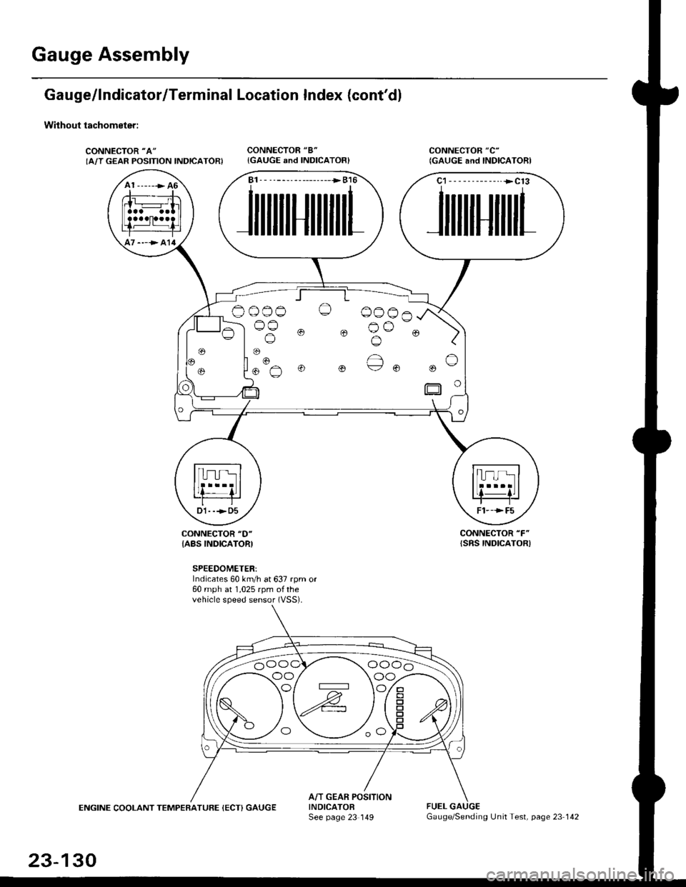
Gauge Assembly
Gauge/lndicator/Terminal Location Index (cont'd)
Without tachometer:
CONNECTOR "A"
IA/T GEAR POSITION INDICATORICONNECTOR "8"
{GAUGE and INDICATOR}CONNECTOR "C"
(GAUGE and INDICAIORI
CONNECTOR "F"
{SRS INDICATOR)CONNECTOR "D"
{ABS INDICATORI
SPEEDOMETER:Indicates 60 km/h at 637 rpm or60 mph at 1,025 rpm ofthevehicle speed sensor (VSS).
ENGINE COOLANT TEMPERATUFE (ECT) GAUGEA/T GEAR POSITIONINDICATOFSee page 23 149FUEL
A1 ------> 46
----> al4
B1. - --------------->B16
JilililHililil1
C1-- - --------..+C13
JililHililL
Oo_o-o O 0006
lus 0 0 Bu-. )
oo/ \oo
23-130
Gauge/Sending Unit Test, page 23 142
Page 1610 of 2189
Vehicle Speed Sensor (VSSI
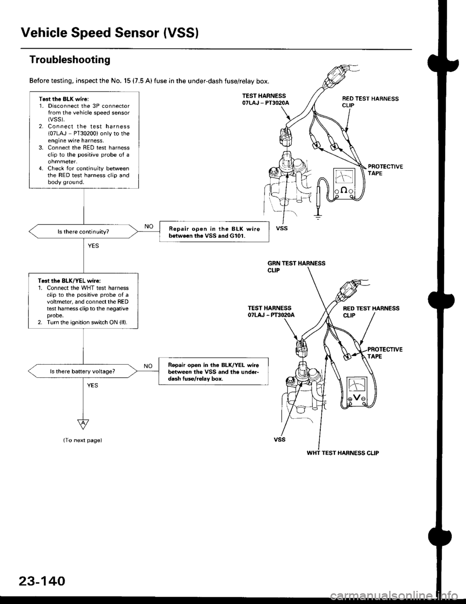
Troubleshooting
Before testing, inspect the No. 15 (7.5 A) fuse in the under-dash fuse/relay box.
TEST HARNESSOTLAJ _ PT3O2OAREO TEST HARNESSCLIP
PROTECTIVETAPE
TEST HARNESSOTLA' . PT3O2OA
(To next page)
Test the BLK wire:1. Disconnect the 3P connectorfrom the vehicle speed sensor(vss).
2. Connect the test harness(07LAJ PT30200) only to theengine wire harness,3. Connect the RED test harnessclip to the positive probe of a
4. Check for continuity betweenthe RED test harness clip andbody ground.
Repair opon in the BLK wireb€twe€n the VSS and G101.ls there continuity?
Te3t the BLK/YEL wire:1. Connect the WHT test harnessclip to the positive probe of avoltmeter, and connectthe REDtest harness clip to the negativeprobe.2. Turn the ignition switch ON {ll).
Repair open in iho BLK/YEL wirebetween the VSS and the under-d6sh tuse/relav box.
vss
GRN TEST HARNESS
RED TEST HARNESS
WHT TEST HARNESS CLIP
23-140
Page 1713 of 2189
)
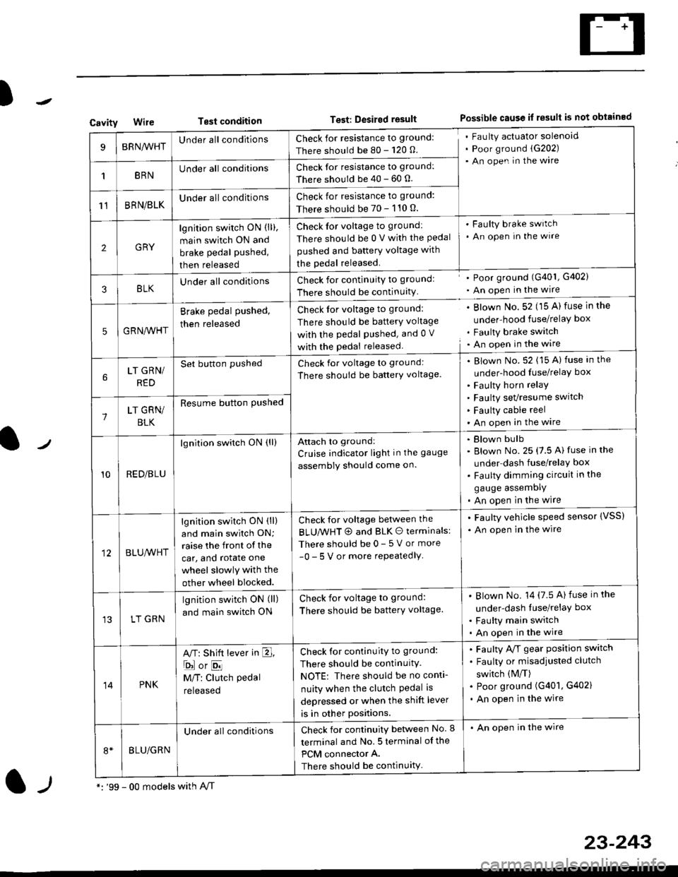
CavityWireTest conditionTest: Desired resultPossible cause if result is not obtained
BRNA/VHTUnder all conditionsCheck for resistance to ground:
There should be 80 - 120 O.
Fau lty actuator solenoid
Poor ground (G202)
An open in the wire
1BRNUnder all conditionsCheck for resistance to ground:
There should be 40 - 60 0.
11BRN/BLKUnder all conditionsCheck for resistance to ground:
There should be 70 - 110 0.
2GRY
lgn jtion switch ON (ll),
main switch ON and
brake pedal pushed,
then released
Check for voltage to ground:
There should be 0 V with the Pedal
pushed and battery voltage with
the pedal released.
'Faulty brake switch
. An open In the wlre
3BLKU nderall conditionsCheck for continuitY to groundl
There should be continuity
' Poor ground (G401, G402)
. An open in the wire
5GRNA,A/HT
Brake pedal pushed,
then released
Check for voltage to groundl
There should be batterY voltage
with the Pedal Pushed. and 0 V
with the pedal released
. Blown No. 52 (15 A) fuse in the
under-hood fuse/relaY box
. Faulty brake switch. An open in the wire
LT GRN/
RED
Set button pushedCheck for voltage to ground:
There should be batterY voltage.
Blown No. 52 (15 A) fuse in the
under-hood fuse/relaY box
Faulty horn relay
Faulty sevresume switch
Faulty cable reel
An open in the wire7LT GRN/
BLK
Resume button Pushed
10RED/BLU
lgnition switch ON (ll)Attach to ground:
Cruise indicator light in the gauge
assembly should come on.
Blown bulb
Blown No. 25 (7.5 A) fuse in the
under dash fuse/relay box
Faulty dimming circuit in the
gauge assemDly
An open in the wire
BLU,A/VHT
lgnition switch ON (ll)
and main swilch ON;
raise the front of the
car, and rotate one
wheel slowly with the
other wheel blocked.
Check for voltage between the
BLUMHT @ and BLK O terminals:
There should be 0- 5 V or more
-0- 5 V or more repeatedlY
. Faulty vehicle speed sensor {VSS)
. An open in the wire
LT GRN
lgnition switch ON (ll)
and main switch ON
Check for voltage to ground:
There should be batterY voltage.
Blown No. 14 (7.5 A)fuse in the
under-dash luse/relaY box
Faulty main switch
An open in the wire
14PNK
A,T: Shift lever in E,
ojorE
M/T: Clutch pedal
released
Check for continuity to ground:
There should be continuity.
NOTE: There should be no conti-
nuity when the clutch Pedal is
depressed or when the shift lever
is in other positions.
Faulty A/f gear position switch
Faulty or misadjusted clutch
switch (M/T)
Poor ground (G401, G402)
An open in the wire
BLU/GRN
Under all conditionsCheck for continuity between No. I
terminal and No. 5 terminal of the
PCM connector A.
There should be continuity
. An open in the wire
*: '99 - 00 models with A,/Tl-,
23-243
Page 1817 of 2189

Contents
How to Use This Manual ICircuit Schematics (see Circuit Index)Fuse/Relaylnformation 6Ground-to-Componentslndex 6-6ComponentLocationPhotooraohs 201Conriector Views 202
Circuit Index
Accessory power socket 155Air conditionerAir delivery'96198 models 61'99-'00 models 61-2Blower controls'96198 models 60'99100 models 60-1Compressor controls 62Fans 63Anti-lock brake system (ABS) 44A/T gear position indicatorCVT 89All except CVT 89-1Automatic transmission controlsAll '96-'98 models except CVT and GX 39All '99100 models except CVT 39-8All GX models 39-8'96-'�98 CVT 39-4'99100 cw 39-12Back-up lightsCoupe and Sedan 110Hatchback l'10-1Brake lightsAll Coupes and'96-'98 Sedans 110-15'99-'00 Sedans 110-16Hatchback 110-17Brake system indicator light'96198 models 7'1'99100 models 71-1Ceiling light 114-3Charging system 22Condenser fan 63Console lights 114Cruise control 34Dash lights 114Daytime running lights 110- 13Engine coolant temperature gauge 81-1Fog lights 110-10Front parking lights 110-2Fuel gauge 81-1Fuse/relay boxUnder-dash 6Under-hood 6-4Underhood ABS 6-3Gauges 81Ground distribution 14Ground-to-Componentslndex 6-6Hazard warning lightsAll except '99100 Sedans 110-6'99100 Sedans 110-8Headlights 110-12Headlight switch 100Heater - See Air ConditionerHorn'96197 models 40'98 model 40-1'99100 models 40-2lgnition key reminder 73lgnition systemAll '96198 models except Dl685 20All '99100 models except D16Y5 with Mn 2O-2All D1685 engines 20-2'99-'00 D 16Y5 with M/T 20
lndicators 80Integrated control unit 70lnterlock systemAll except'96J98 CVT 138'96198CVT 138-1License plate lightsAll Coupes and '96-'98 Sedans I l0-3'99100 Sedans 1 10-4Hatchback 110-5Low fuel indicator light 74Moonrool'96197 models |22'98-'00 models 122-1Odometer 81Oil pressure indicator light 80-3Power distributionBattery to ignition switch, fuses, and relaysFuses to relays and components 10-2Power door locksAll models without keyless entry 130'96-'98 models with keyless entry 130-2'99100 models with keyless entry 130-12Power mirrorsWithout detogger 141With defogger '141-2
Power windows 120Programmed fuel injection system (PGNr-Fl)All '96-98 models except D1685 23All '99-'00 models except D16Y5with M/T and D1685 24All D1685 engines 25'99100 D16Y5 with M/T 23Radiator fan 63Rear window defogger'96-,98 models 64'99100 models 64-1Seat belt reminder 73Security system'96.'98 USA HX, LX, EX 133'96-'98 Canada EX, Si 133'99TOO USA HX, LX, EX, DX.V Si 133-4'99100 Canada EX, Si 133-4All CX and DX models 133-8Speedometer 81Starting systemA./T (All except Dl685) 21A"/r (D16Bs) 21-1Manualtransmission 21-2Slereo sound system 150Supplemental rastraint system (SRS) 47Tachometer 81TailliqhtsAllboupes and'96-'98 Sedans 110-3'99100 Sedans 1 10-4Hatchback 110-5Trunk light 114-3Turn signal lightsAll except'99100 Sedans 110-6'99-'00 Sedans 1 10-8Vehicle speed sensor (VSS) 33Wiper/washerFront 91Rear 92
10
Page 1840 of 2189

Ground-to-Components I ndex
f.,lONOTE: All ground wires are BLK unless otherwise noted.
GroundPageComponents or Circuit Grounded
Battery (BLKYEL)
Steering pump bracket
t+-rg ITransmission housing
l
G101
(-1)
G101
(-2)
14-2
and
14-3
ano
14-1
Powertrain or engine control module (PG1 and pG2 are BLK: LG1 and LG2 are
BRN/BLK), EGR control solenoid valve (CW, EGR valve and lift sensor (Dt6yS enginewith M,/T), Engine coolant temperature switch, pGM-Fl main relay, power steeringpressure switch (USA), Primary HO2S (D16Y5 engine with l\/,/T), Vehicle speed sensor,VTEC pressure switch (D16Y5/D16Y8 engines), CKF sensor (BRN/BLK), Transmission
control module (CYf) (Pc1 is BLK: LG1 is BRN/BLK)
Shielding betvveen the PCM or ECM and these components (all have BRN/BLK wires):
CKF sensor, TDC/CKP/CYP sensor. Primary and secondary heated oxygen sensors.
Knock sensor (CWDl6YB engine), Mainshaft speed sensor (AiT except CVT),
I Countershaft speed sensor (A/T except CVf)
Shielding between the TCM and these components (CVT) (all have BRN/BLK wires):
Drive pulley speed sensor, Driven pulley speed sensor, Secondary gear shaft
speed sensor
Powertrain or engine control module (PG1 and pG2 are BLK; LG1 and LGz are
BRN/BLK), EGR control solenoid valve (D16Y5 engine), EGR valve (Dt685), Engine
coolant temperature switch, Fuel pressure regulator shut-off solenoid valve (D1685),
PGM-FI main relay, Power steering pressure switch (USA), Vehicle speed sensor, VTECpressure switch (All except D16Y7 engine), CKF sensor (A
except 81642) (BRN/BLK)
Shielding between the PCM or ECM and these components (all have BRN/BLK wires):
CKF sensor, TDC/CKP/CYP sensor, Primary and secondary heated oxygen sensors,
Knock sensor (All except D16Y7 engine), i/ainshaft speed sensor (Arf except CW),
Countershaft speed sensor (A,/T except CVf), Drive pulley speed sensor (CW), Drivenpulley speed sensor (CVT), Secondary gear shaft speed sensor (CVf)
I Badiator fan motor, Right front parking/turn signat tight, Right headtight
G20214-4I Cruise control actuator, Left front parking/turn signal lights, Left headlight, Rear window
I washer motor, Windshield washer motor, Washer fluid level switch (,99-'00 Canada)
G401| +-o
and
14-7
Accessory power socket, Brake fluid level switch, Clutch interlock switch (M/T), Clutchswitch (lillT with cruise/D16Y5 engine with MfD, Combination wiper switch (Z wires),
Cruise control main switch, Cruise control unit, Dash lights brightness controller, Data
link connector, Daytime running lights control unit (Canada), Gauge assembly, Horn('96-'97 models), Integrated control unit, Interlock control unit (ArI), Keyless door lock
control unit ('99-'00 models with keyless), Moonroof close and open relays, Moonroof
switch, Park pin switch (A/r), Power window relay, Rear window defogger relay, Rear
window defogger switch ('96-'98 models), Steering lock, Stereo radio tuner (,96-,98
USA: LX, EX, and HX), Turn signal/hazard relay, Windshield wiper motor.....plus
everything grounded through G402
6-6
Page 1859 of 2189
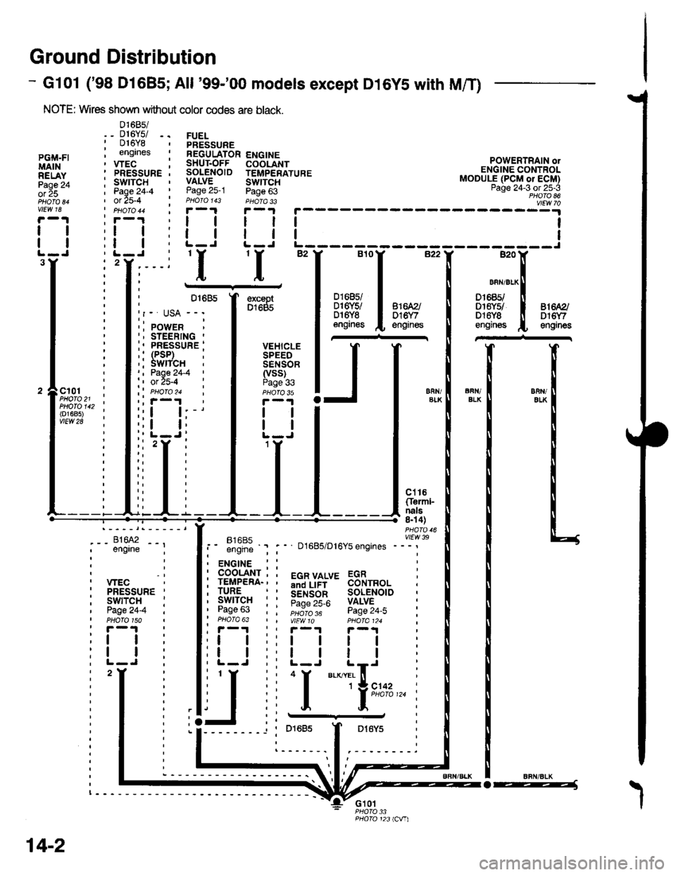
Ground Distribution
- Gl01 ('98 Dl685;All '99-'00 models except D16YS with M/T)
NOTE: Wires shown without color codes are black.
01685/_ D16Y5/ -.016Y8engrnes
.__-;,#'-_,--', engrne ;
, wEc: PRESSURE '
, swtTcH :I Page24-4 iI PHOTO 150: r -'l
:t | :
:l | :,L-J.
FUELPRESSUREREGULATOR ENGINESHUT.OFF COOLANTSOLENOID TEMPERATUREVALVE SWTTCHPage 25-1 Page 63PHOIO 143 PHOTA 33r-1F-.|
llll
lltlL-J L-J
POWERTRAIN olENGINE CONTROLMODULE (PCM or ECM)Page 24-3 ot 25-3PHOTO 86
----:y4
tl
tl
PGi,|.FIMAINRELAYPage 24ol 25
vlEw 18
tl
tl
3Y'I'I
excaptD1685
VEHICLESPEEDSENSOR(vss)Page 336FN/ELKERll/EIKcl01PHOTO 21PHOTO 142(o1685)vtEw 28
ct16Cferml-nals8n 4)
FltaFt( vttw 39t- .''iiti ' " D1685/D16Y5 engrnes ---'
t2
. ENGINE : :
i 933'?il-; i 5"T,Yf,*' 33i,"o, i
i lgfft" i I S.ir1".l^ soL€NorD :' Pase 63 : : ;;;;; - pase 24.i :' PHOTO 63 | | VtEWlO pHOIa124 ;, r-1 | , F-.t r-.r
:l | ;:l | ! | :;t | :,t | | | ;
j,f
ii T.__.,|,,,,,.
j
--
----- --l i otoas I Dr6y5 :
:------.1.--------.
14-2
o-----J
Page 1887 of 2189
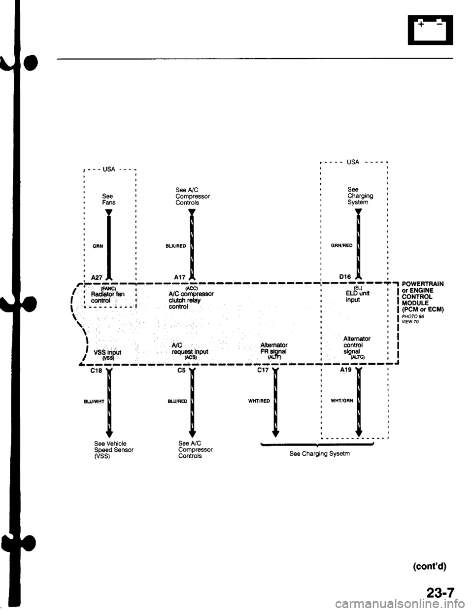
: , See ly'C ' See, See ' Compressor : Charging' Fans : Controls ; System
'YI Y:Y
:l: ll:[
il: l:l
i*"1 i "*"."1 : o"",".o1
, r | : -^*l
ili I i Ii. *, I i rrz.l, ; ot. I'.--..--r-
/i**fffi'* I r,rcffi"oro, i e.St*I ; cornrd ' clulcfi rday ' nput
| .-,---;---l COntrOl
\'
\;t ' Altsrnqtor! Nc Altemator : conrol
/, u.1;lf* roqrsr rnpd FRfrgd ; tSJ",
&rrr:rr
SeeCharornoSystein - :
Y:
!i
u".o I i
i:
o,. .!, iPOWERTRAIN
l*.]["n i 13'"',1+?3.': I MODULE; | (PcM or EcM)
i lw,t?'"
Altornstor ; Iconrol i I
$:--lJ
"''I
',n,-
I
I
See VehicleSpeed Sensorryss)
*[
".,^."
!
I
t
See NCCompressorControls
.r_l
See Charging Sysetm
(cont'd)
23-7
Page 1900 of 2189
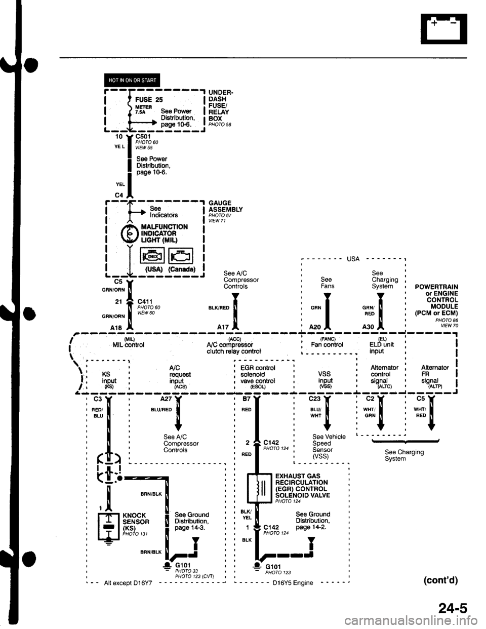
i--I,*.;----l
I I ffl* s€€ Pow€' I
!---h=js:q-l
r'1ltii*",
! il"Jiisa"
;ll
i-[*-*"".""--l
! @ffi[+[ffI. !
! Ir6rer i
L--L-,sr@lc5Y
UNDER.DASHFUSE/RELAYBOXPHO|O 58
GAUGEASSEMBLY
;------- USA -------,
see ly'c i S"" :Compressor , See Charging ;Controts , Fans System , POWERTRAIN-
li*t*rr,, ".o^.of, i """f """,tr' i tff'$fit!
Tl,!,
"0o -;;l
i ;;l ^*l i
n"""j.F,rH;
Irs I A17 A :A2oA moA :
,'-----ri;)---7ol------T-;;l----,il--i-----'r,' r',lrr- di-ritror lvc "orip-E""or : Fa; ;;iror eldiinit : II clutci relay conlrcl InPd I\tri---"---i t!9--. i-;ter";--I i{r,*+-i 1s"'*.'lr I t'lc : EGR control : : Atternator I A[emator ]'. I KS : requ6st ; solenoid ; VSS ' control , FR Ia , inDut : inout , \iave control , inpul , sional ' sianal I, , (Ks) i i*"1 , (Esor, _jt,__.j-_JgL-.j__ ,^:_j3------- --- --- -- -.4- -- -- -,1-- - -
i"fiti".,ff:l i"111 iffilifili"F"l
i*l i + i I i
"+
i-"1 :''"1T'See LiC , I ' See vehicle t--'---'-'
ComOressor , 2 ^C142 : SpeedContiofs | | PHoro124 i Sensor
i ft> i :"::l
' ".o
|
",o,o,,0
i lisi: 3i&S**n,"n
i Lti-t i i rh;ry,'s;3+r"" i
: I ""n,".*l iiltll lS'"",.?^8"'$lli'til ""n'"'*! iil-il]J5ff#f."ruuu
i ll.,*'o.* ! *o,o,no i i l'.lT- seecround
: FflSI8$" i Btr"lifiiJ}': i i *i[ Bi,i"EL'""
; f lJffi""' !**;' i i":-lei'u!,7,,"
ws{u'
(cont'd)
24-5
Page 1912 of 2189
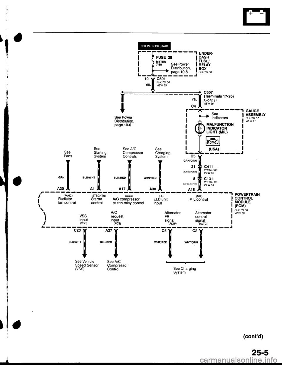
@----t UNDER.
I t FUSE 2s I p.4:!
| ) Iff" ses Power | ;"Eiii
I l------+ 3l'i:?'J:" tF,%.,L--*----il--l-J -
'o Y F;%.YELI v/Ew 55
f
--- - - - - - - - - - -;f '-iminats tz'zo1
I c+ lv'rwto
Y r--'1r-:-----'l GAUGE
see Power ! f* l"?i*,".. ! f,s";"ty"ttDisiribution, I , | vtEwTlpass10'6
i @$eFH,t* i
! T16r I
see see !y'c see I I
-ruil |See Startrnq ComDressor Charorno L--V---J----JFans System Conliols Syste-m - C5 y
I I I I
"".11-lro,..
| | | | o"no"n!f[?iSuo
GUN
I
BLUVHT
I
BLKnEo
I
GRNFED
f sVC131
*o I o, .1. o', ,l o.o .l
o"*o*l i[?1o"*
,r---U,a"i---strF-*-*"r"tr8*i-#%,.----;w;,---lneffi [it^'" tan control control ciutch reiay control Input | (pCM) -._ | puoroear AJc Atternaror Atternator l. iir*.i VSS rsquest FR controt I
i '[g3l i"R8!, ",gl,1o "'11'%, IrL------ --------Jc23 ll, l27Y "ur "rX
tlllBtUw}rI
I
BLU,FEo
I
w8r RED I wxr onr I
IIIIYYYY
See Vehicle See A,/C -'-dSpeedSensor Compressor(vss) contiot 3i:,""I"'n'"n
(cont'd)
25-5
I
Page 1916 of 2189
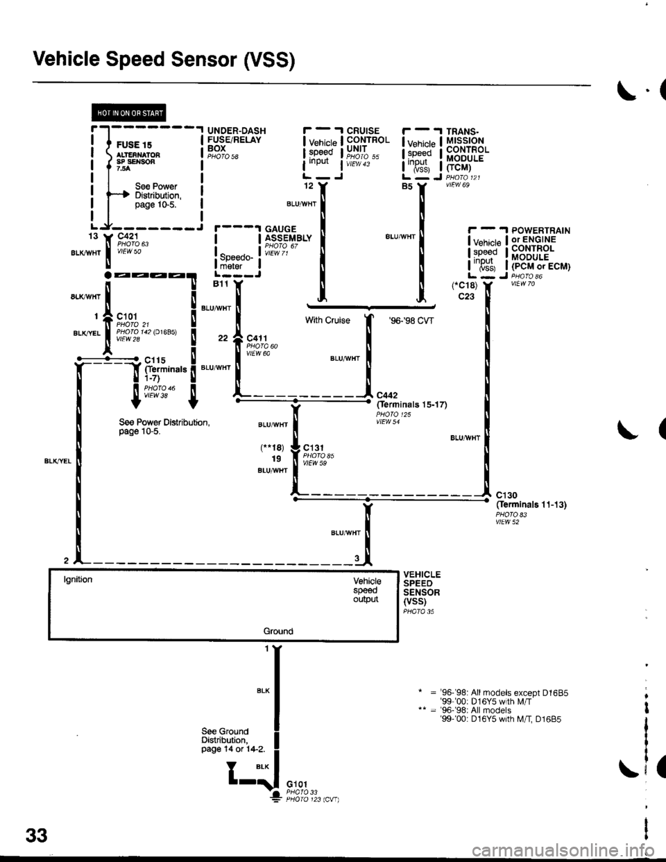
Vehicle Speed Sensor (VSS)
il';;---lI ALTENNATOA I
I I""::,",,", !
Lr_f1l_i
".*,1,[ 9#":1"
\.(
UNDER-DASHFUSE/RELAYBOXPHO|O 5a
I v"ni"t"
l:g9qd
iineilt i
12
CRUISECONTROLUNIT
vtEw 43
I v"ni"p I
l:p"gd I
I'T$, I
TRANS.MtsstoNCONTROLMODULE
FCM)
vtEw 69
! !iio',6T""f
EtuwHr|
!y:ll*!Bb'^i1?'J.'
! so""oo- ! iffiilr*J l;6';irtE!;i#:*! il il iiTs'l, iipEr',r"L---J I I L - J D.^..1*B11 Y [ [ (-C18) Y vtLNTo
l;i"i;'! [ [ l'ffi, liib-r,ro,ecu1
See Power Distribution,page 10-5.(
lgnitjonVohielespeeoouptn
Ground
Y' """-' Oerminats 1.t-13)
vlEw 52
VEHICLESPEEDSENSOR(VSS)PHATA 35
= '96- 98: Allmodels except D1685'99 00: D 1 6Y5 w th Lr/T= '96-'98: All models'99-'00: D16Y5 with M/I D1685
.i,
a33