vehicle speed sensor HONDA CIVIC 1998 6.G Repair Manual
[x] Cancel search | Manufacturer: HONDA, Model Year: 1998, Model line: CIVIC, Model: HONDA CIVIC 1998 6.GPages: 2189, PDF Size: 69.39 MB
Page 1917 of 2189
- How the Gircuit Works
With the ignition switch in ON (ll) or START (lll),
battery voltage is supplied through fuse 15 and
the BLI(WHT and BLK/YEL wire to the vehicle
speed sensor (VSS). The sensor is grounded by
the BLK wire to G1 01 . The speedometer and
other control units in the circuit supply about 5
volts to the BLU/WHT wire. The vehicle soeed
sensor (VSS) intermittently grounds the
BLUMHT wire which generates a pulsed signal
in it. The number of pulses per minute
increases/decreasos with the soeed of the car.
Reter to th€ Service Manual (Section 23, Electrical)
tor specific tosts or troubleshooting procedures.
33-1
Page 1921 of 2189
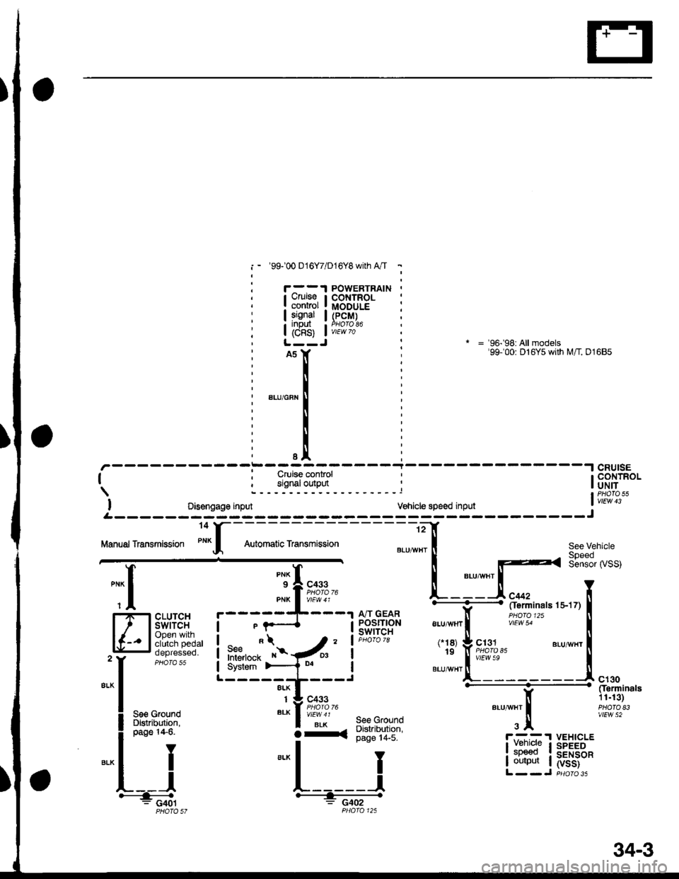
i - '99100 016Y7/D16Y8 with A"/T -
Cruiseconrolsgnal
i8s) i
iil
POWERTRAINCONTROLMODULE(PcM)
* = '96-'98: All models'99100: D16Y5 with M/T, 01685
-----i-----.lcRU|sE
| ; Cruise control ' I CONTROL
signaloutput ' |oNirI PHATO 55
I oisengage input vehicle speed input ' vtEw 13
.--------;---- ---J
See Vehicle
Sensor rySS)
See GfoundDigtribution,page 14-5.
I
J
"{
,--r-s=-.
CLUTCHswtTcHOpen withclutch pedaloepresseo.
A/T GEARPOSITIONswtTcH
L- ----
ALU,ryVHT
3x
ct30Cferminals11.13)PHATO E3vlEw 52See GrolndDlslribution,page 14-6.
IY
ll
L__l#: G401
lI:::1" I
I output I
VEHICLESPEEDSENSOR(vss)
O-a
34-3
Page 1922 of 2189
Gruise Control (cont'd)
- How the Circuit Works
The cruise control system uses mechanical and
electrical devices to maintain the car's sDeed at a
setting selected by the driver.
System Description
The cruise control unit receives command signals
from the crurse control main switch and the cruise
control SeVResume switch. With the ignition switch
in ON (ll) or START (lll), voltage is provided to the
cruise control main switch through fuse 14. When
you push the switch to ON, power is provided to the
cruise control unit and the brake switch.
The cruise control unit receives information about
operating conditions from the brake switch, the
vehicle speed sensor (VSS), and the clutch switch
(manual transmission) or the A,/T gear position
switch (automatic transmission). The cruise control
unit then sends signals to the cruise control actuator
which regulates the throttle position to maintain the
selected speed. The conlrol unit compares the
actual speed of the car to the selected speed. The
control unit then uses the result of that comoarison
to open or close the throttle.
The brake switch releases the system's control of
the throttle at the instant you press on the brake
pedal. The switch sends a signal to the control unit
by removing power from the normally closed brake
input (GRY wire), and providing power at the
normally open brake input (GRN/vVHT wire). The
control unit responds by allowing the throttle to
close. The clutch switch or the A,/T gear position
switch sends a "disengage" signal to the control unit
that also allows the throttle to close.
The cruise control system will set and automatically
maintain any speed above 25 mph (40 km/h). To set
it, make sure the main switch is on and the switch
indicator is on. Then, after reaching the desired
speed, press the SET switch. This sends a "set"
signal to the cruise control unit which, in turn,
controls the cruise control actuator to maintain the
set speed.
When you push the SET switch and the cruise
control system is on, the "cruise control" ON
indicator lights up.
34-4
(
You can cancel the cruise control system by
turning the main switch off . This removes power to
the control unit and erases the set speed from
memory. lf the system is disengaged temporarily
by the brake switch, or clutch switch, and the car's
speed is still above 25 mph, press the resume
switch: the car will automatically return to the
previously set speed.
For gradual acceleration without pressing the
accelerator pedal, push the RESUME switch and
hold it there. This will send an "acceleration" signal
to the control unit. When you release the switch, the
system will be reprogrammed for the new speed. To
slow the car down. oush the SET switch in and hold
it there. This sends a "deceleration" signal to the
control unit, causing the car to coast. When the
desired speed is reached, release the SET switch.
This reprograms the system tor the new speed.
Refer to the Service Manual (Section 23, Electrical)
tor specific tests or troubleshooting procedures.
(
a
Page 1923 of 2189
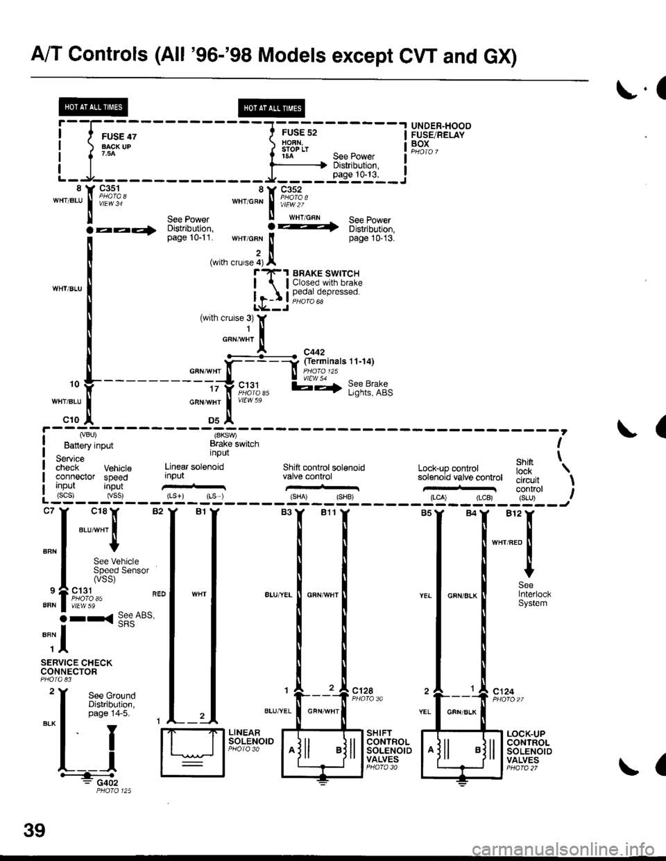
A/T Controls (All '96-'98 Models except CW and GX)
r.(
r5A see power I
--li$"i':,--iL-.At----- __*____..,,53-j"i__8 Y 93^s_1- 8Y C352'"'".u
I iii'i"' ""'o"* | i#?1o.'
ll see power ll wrr cnn See Power
la--- oisirioution, ! -t 6iri,iortion,
[--*
t"*tr*t1,'.':,:;i. wHr GFN lt page 10-13.
,i(with crurse 4) Al"'rl(-1 BRAKE swrrcH
| lClosed.with brake
Ir-I Il,?,|fll,"P'"""oL*--J
c18lr 82
"ar-"t I
I
See VehicleSpeed Sensor(vss)
ct31PHO|O 35vtEw 59
r< See ABs'
UNDER"HOODFUSE/RELAYBOXI
I
I
BFN
9
BFN
o
""il
SERVICE CHECKCONNECTOR
See GroundDistribution,page 14-5.
I
YEL
c124
L__lH:""".: G402
SHIFTCONTROLSOLENOIDVALVES
LOCK-UPCONTROLSOLENOIDVALVES
,. L ---- - - --.#ku" :::::'o f
---------tty"c;11,, l;-,f l;?t?:if,-:;tr *";.!, *"
c10 ,| Ds^'
I Lvou, (SKSV,
! Battery input Brake lwitch I
service nPUt ehin t;;;;i- Vehrcte Linear sotenoid Shift controt sol€noid Lock-up conkol iJ'[
'\
connector speed input valve conhol solenoid vatve controt tliiJ"it \uo trut tconrrol t: (scs) (vss) {Ls}) rLs ) {sHA' {SHB, (LCA) (LCB) {S-U) .--:-'--J
ct28
39
GFN/ALK
(
Page 1927 of 2189

L-L----:-------J----L"egyJ*"" !tr;:tl1tfl i*"?]( 9;%, 8Y ge-q? LJ-------,;li, ! *rr1-....^^ s€s tuwer *"to"n ! if?ror ,r"r,o"n - sse power 14 y g4^1_q --
I
I
o*"clt](/img/13/6068/w960_6068-1926.png)
AIT Controls ('96-'98 CVT)
L-L----:-------J----L"egyJ*"'"' !tr;:tl1tfl' i*"?]( 9;%, 8Y ge-q? LJ-------,;li, ! *rr1-....^^ s€s tuwer *"to"n ! if?'ror' ,r"r,o"n - sse power 14 y g4^1_q --
I
I
o*"'clt. *'"1,!. tad;1di3]
t
-""
I HFr:{tv][[:F I
*l """-tl-.
"*,
*-,-*l
t;
^,.[
"-;;[ 1#E;;;::";mi
.aa4 ;;r;;", : ----+ u,"i.,-uon, i;;;;r.
i {vBt) (sToP sw) (Gl) flc1l
! Battery input Brake switch lgnilion tgniuon| -^-,^^ ' inpui fipr,- i;;i;iSeMce input i;put iiput t
| #;if vehicle Engin€ Drive putley Dnven puttey secondary \-
I cooneaor speed speed speeci sensor speed iens6r gsarshaft'speed t
I
\fa
I input input input input input s€n8or inputI (scsJ {vss} (NE) {ltm) INDN) (vEL)L____-__ -______J".
I
*,ff
I
:l
[
"ili[_==___j
: : : j
I i:isi, fi, &ru"n t$=:{:::==l
[:-,*';|i-.t[d
F'*,Y''"T:."".
H Sig,il H F"ii${* H
$':lry!}Hi"
3lT:T:gl ""lr *=f __-*=!".*,
I ;$f
--l"ur
oFN'BLur !iEi?20
I -rJ-----i.:,-,----=,--^:lrRANsMtsstoN| ;;n's'"
J i$f;:' Si$? $"'":Tiii:e{i.ii'i::^ Is:*",:i !fi8}ltP.n*,;-=:.=-: G402I sround ground grouno I l,llir%lliPHO,O 125 L___-___
39-4
!'cror
Page 1980 of 2189
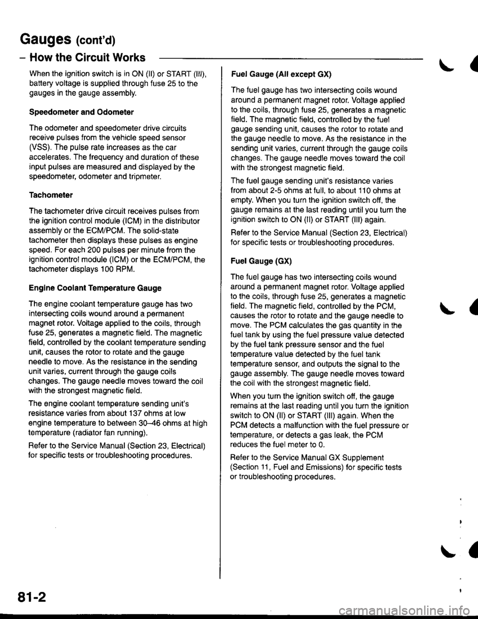
Gauges (cont'd)
- How the Gircuit Works
When the ignition switch is in ON (ll) or START (lll),
battery voltage is supplied through fuse 25 to the
gauges in the gauge assembly.
Speedometer and Odometer
The odometer and soeedometer drive circuits
receive pulses from the vehicle speed sensor
(VSS). The pulse rate increases as the car
accelerates. The frequency and duration of these
input pulses are measured and displayed by the
speedometer, odometer and tripmeter.
Tachometer
The tachometer drive circuit receives pulses from
the ignition control module (lCM) in the distributor
assembly or the ECM/PCM. The solid-state
lachometer then displays these pulses as engine
speed. For each 200 pulses per minute from the
ignition control modul€ (lCM) or the ECM/PCM, the
tachometer displays 100 RPM.
Engine Coolant Temperature Gauge
The engine coolant temperature gauge has two
intersecting coils wound around a permanent
magnet rotor. Voltage applied to the coils, through
fuse 25, generates a magnetic lield. The magnetic
field, controlled by the coolant temperature sending
unit, causes the rotor to rotate and the gauge
needle to move. As the resistance in the sending
unit varies, current through the gauge coils
changes. The gauge needle moves toward the coil
with the strongest magnetic field.
The 6ngine coolant temperature sending unit's
resistance varies from about 137 ohms at low
engine temperature to between 3H6 ohms at high
temperature (radiator fan running).
Refer to the Service Manual (Section 23, Electrical)
for specific tests or troubleshooting procedures.
81-2
(
Fuel Gauge (All except cX)
The fuel gauge has two intersecting coils wound
around a permanent magnet rotor. Voltage applied
to the coils, through tuse 25, generates a magnetic
field. The magnetic field, controlled by the fuel
gauge sending unit, causes the rotor to rotate and
the gauge needle to move. As the resislance in the
sending unit varies, current through the gauge coils
changes. The gauge needle moves toward the coil
with the strongest magnetic field.
The fuel gauge sending unit's resistance varies
from about 2-5 ohms at full, to about 110 ohms at
empty. When you turn the ignition switch off, the
gauge remains at the last reading until you turn the
ignition switch to ON (ll) or START (lll) again,
Refer to the Service Manual (Section 23, Electrical)
for specific tests or troubleshooting procedures.
Fuel Gauge (GX)
The fuel gauge has two intersecting coils wound
around a permanent magnet rotor. Voltage applied
to the coils, through fuse 25, generates a magnetic
field. The magnetic field, controlled by the PCM,
causes the rotor to rotate and the gauge needle to
move. The PCM calculates the gas quantity in the
fuel tank by using the fuel pressure value detected
by the tuel tank pressure sensor and the fuel
temperature value detected by the fuel tank
temperalure sensor, and outputs the signal to the
gauge assembly. The gauge needle moves toward
the coil with the strongest magnetic field.
When you turn the ignition switch off , the gauge
remains at the last reading until you turn the ignition
switch to ON (ll) or START (lll) again. When the
PCM detects a malfunction with the fuel pressure or
temperature, or detects a gas leak, the PCM
reduces the fuel meter to 0.
Refer to the Service Manual GX Supplement
(Section 11 , Fuel and Emissions) for specific tests
or troubleshooting procedures.
a
a
Page 2125 of 2189
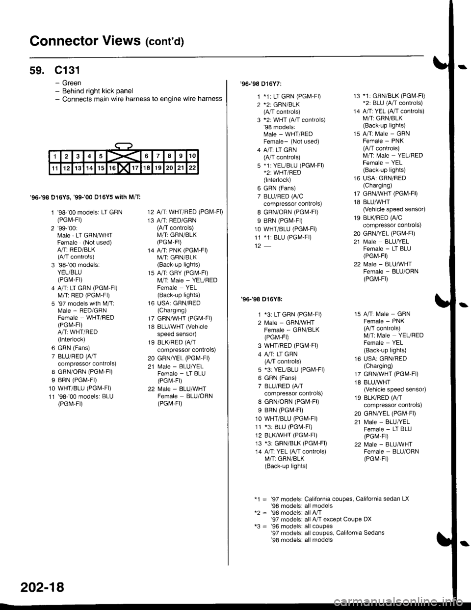
Connector Views (cont'd)
59. Cl31
- Green- Behind right kick panel- Connects main wire harness to engine wire harness
'96.'98 D16Y5,'99-'00 D16Y5 with M/T:
1 '98-'00 models: LT GRN(PGl\4-Fl)
2'991001Male'LT GRNMHTFemale (Not used)A/Tr RED/BLK(A/T controls)
3 '98r00 models:YEL/BLU(PGrV-Fr)
4 A/T: LT GRN (PGl\.4-Fl)
lVl/T: RED (PGi.4-Fl)
5 '97 models with l\4/T:Male - RED/GRNFemale - WHT/BED(PGl\,4-Fl)
A/T: WHT/RED(lnterlock)
6 GRN (Fans)
7 BLU/RED (A/T
compressor controls)
I GFN/OnN (PGl\4-Fl)
I BRN (PGr\,4-Fr)
10 WHT/BLU (PGM-Fl)
11 '98-'00 models: BLU(PGir-Fr)
12 A,/T: WHT/RED (PG|VI-FD
13 A/T: RED/GRN(A/T controls)M/T: GRN/BLK(PGr\,1-Fr)
14 A/T: PNK (PGM-FDM/T; GRN/BLK(Back-up lights)
15 A/T: GRY (PGl\,l-Fl)
l\,4,rT: Male - YEUREDFemale YEL(Back-up lights)
16 USA GRN/RED(Charging)
17 GRN,ryVHT (PGM FD
18 BLUAVHT (Vehicle
speeo senso4
19 BLK/RED (A,IT
compressor controls)
20 GRN/YEL (PGM-FD
21 N,4ale - BLU/YELFemale - LT BLU(PGM-Fr)
22 Male - BLU/WHTFemale BLU/ORN(PGt4,Ft)
202-18
'96.'98 016Y7:
1 *1: LT GRN (PGM-F|)
2 *2: GRN/BLK(A/T controls)
3 *2: WHT (A/T controls)'98 models:[rale - WHT/REDFemale- (Not used)
4 A/Ti LT GRN(A/T controls)
5 *1i YEL/BLU (PGM-Fl)*2: WHT/RED(lnterlock)
6 GRN (Fans)
7 BLU/RED (A/C
compressor controls)
I GRN/ORN (PGlvl-Fl)
9 BRN (PGT,I-FD
10 WHT/BLU (PGM-Fl)
11 *1r BLU (PGL4-F|)
'96-'98 016Y8:
1 *3: LT GRN (PGlvl'Fl)
2 lvlale - GRNIVHTFemale - GRN/BLK(PGr\.4,F1)
3 WHT/RED (PGl\,4-F0
4 A"rT: LT GHN(A/T controls)
5 *3: YEUBLU (PGM-Fl)
6 GRN (Fans)
7 BLU/RED (A/T
compressor controls)
8 GRN/ORN (PGr\4'F|)
9 BRN (PG|\4-F|)
10 WHT/BLU (PG[,4-Fr)
11 *3: BLU (PG[.4-F|)
12 BLK,ryVHT (PGl\4-Fl)
13 *3r GBN/BLK (PGM-Fl)
14 A/T: YEL (A,rT controls)M/T: GRN/BLK(Back-up lights)
13 *1i GFN/BLK (PGl\4'Fl)*2: BLU (A/T controls)
14 A/Ti YEL (A/T conlrols)M/T: GRN/BLK(Back-up lights)
15 A/Ti Male - GRNFemale - PNK(A/T conkols)lvl/tT: Male - YEL/REDFemale - YEL(Back up lights)
16 USA: GRN/BED(Charging)
17 GRN,^/VHT (PGIVI.FD
18 BLU,ryVHT(Vehicle speed sensor)
19 BLI(RED (A/C
compressor controls)
20 GRN/YEL (PGM-Fr)
21 ftIale BLUffELFemale - LT BLU(PGM,Fl)
22 Male - ELUMHTFemale - BLU/ORN(PGrvl,Fr)
15 A/Tr l\,4ale - GRNFemale - PNK(A/T controls)lVl/T: [/ale YEUBEDFemale - YEL(Back'up lights)
16 USA: GRN/RED(Charglng)
17 GRN,ryVHT (PG[r-Fl)
18 BLUAVHT(Vehicle speed senso4
19 BLK/RED (A/T
compressor controls)
20 GRN/YEL (PG[' Fl)
21 Male - BLU//ELFemale - LT BLU(PGr,1-FD
22 l\,4ale - BLUMHTFernale BLU/ORN(PGt
-Ft)
*1 = '97 models: California coupes, Californla sedan LX'98 modelsi all models*2 = '96 models: all A,rT'97 modelsr all A"lT except Coupe DX*3 = '96 models: allcoupes'97 models: all coupes, California Sedans'98 models: all models
Page 2126 of 2189
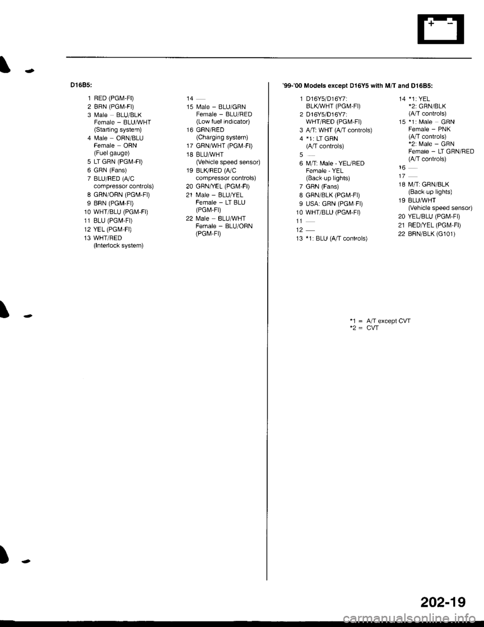
Dt685:
1 RED (PG[,1-F0
2 BRN (PGM,F|)
3 Male BLU/BLKFemale - BLUMHT(Starting system)
4 lrale ORN/8LUFemale ORN(Fuelgauge)
5 LT GRN (PGM-FD
6 GRN (Fans)
7 BLU/RED (r,/C
compressor controls)
8 GRN/ORN (PGM-Fr)
9 BRN (PGM-FD
1O WHT/BLU (PGM.FO
11 BLU (PGM-F|)
12 YEL (PGM-FI)
13 WHT/BED(lnterlock system)
14
15 l\.4ale - BLU/GRNFemale - BLU/RED(Low fuel indicator)
16 GRN/RED(Charging system)
17 GRNA/VHT (PGl\.4 FD
18 BLUAVHT(Vehicle speed sensor)
19 BLTVRED (r,/C
compressor controls)
20 GBN/YEL (PGr\.4-FD
21 N4ale - BLU/YELFemale - LT BLU(PG r\,,r- Fr)
22 l\4ale BLU&VHTFemale - BLU/ORN(PGr,4-Fr)
\
)
'99-'00 Models exceot D16Y5 with M/T and D1685:
1 D16Y5/D16Y7:BLI(WHT (PGM.FI)
2 D16Ys/D16Y7:wHr/RED (PGt\4-Ft)
3 A,rT: WHT (4,/T controls)
4 *1: LT GRN(A/T controls)
6 M/T: Male - YEUREDFemale - YEL(Back up lights)
7 GRN (Fans)
8 GRN/8LK (PG[,4-Fr)
9 USA: GRN (PGf.4 Fl)
1O WHT/BLU (PGM-FD
13 *1: BLU (A/T conkols)
14 *1: YEL*2: GRN/BLK(A/T controls)
15 *1: Male GRNFemale - PNK(A/T controls)*2: Male - GRNFemale - LT GRN/RED(A,fT conkols)
18 M/T: GRN/BLK(Back up lights)
19 BLUMHT(Vehicle speed sensor)
20 YEUBLU (PGI\4-FD
21 RED/YEL (PGt\,'l,FD
22 BRN/BLK (G101)
*1 = A/T except CVT
202-19
Page 2137 of 2189
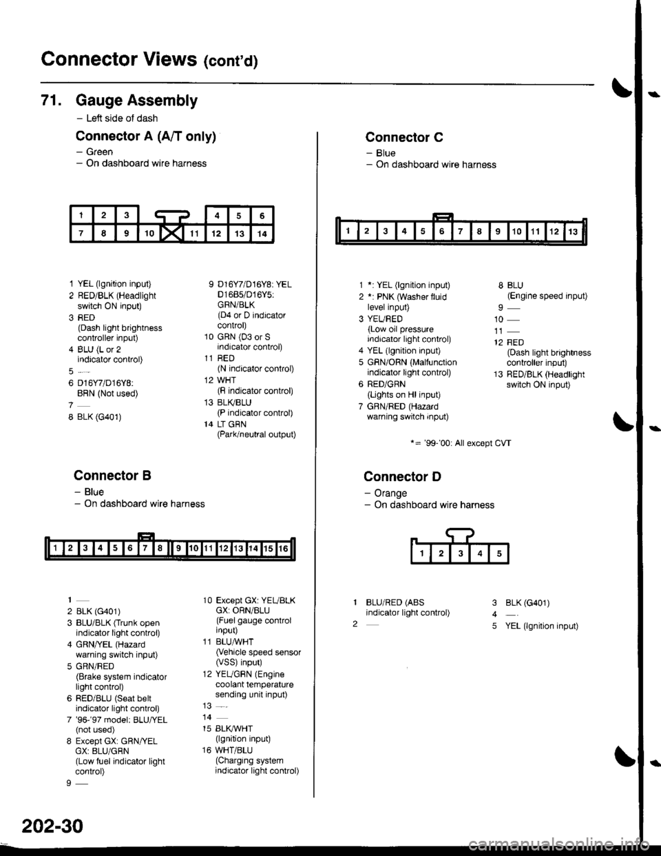
Connector Views (conrd)
71. Gauge Assembly
- Left side of dash
Connector A (A/T only)
- Green- On dashboard wire harness
1 YEL (lgnition input)
2 RED/BLK (Headlight
switch ON input)
3 RED(Dash light brightnesscontroller input)
4 BLU (L or 2indicator control)
6 D16Y7/D16Y8:BRN (Not used)
8 BLK (G401)
Connector B
- Blue- On dashboard wire harness
2 BLK (G401)
3 BLU/BLK (Trunk openindicator light control)
4 GRN/YEL (Hazard
warning switch input)
5 GRN/RED(Brake system indicatorlight control)
6 RED/BLU (Seat beltindicator light control)
7 '96-'97 model: BLU,ryEL(not used)
8 Except GX: GRN/YELGX: 8LU/GRN(Low fuel indicator lightcontrol)
9 D16Y7/D16Y8: YEL01685/016Y5:GRN/BLK(D4 or D indicatorcontrol)
10 GRN (03 or Sindicator control)
11 RED(N indicator control)
12 WHT(F indicator control)
13 BLI(BLU(P indicator control)
14 LT GBN(Park/neutral output)
10 Except GX: YEUBLKcX: ORN/BLU(Fuel gauge controlinput)
11 BLUAVHT(Vehicle speed sensor(VSS) input)
12 YEUGRN (Engine
coolant temperaturesending unit input)
14
15 BLI(IVHT(lgnition input)
16 WHT/BLU(Charging systemindicator light control)
202-30
Connector C
- Blue- On dashboard wire harness
1 *: YEL (lgnition input)
2 *: PNK (Washer lluidlevel input)
3 YEUBED(Low oil pressureindicator light control)
4 YEL (lgnition input)
5 GRN/ORN (Malfunctionindicator light control)
6 RED/GRN
{Lights on Hl input)
7 GBN/RED (Hazardwarning switch input)
*= '99-'00: All except CVT
Connector D
- Orange- On dashboard wire harness
BLU/RED (ABS
indicator light control)
8 BLU(Engine speed input)
10
12 FED(Dash light brightnesscontroller input)
13 RED/BLK (Headlightswitch ON input)
I
2
3
4
5
BLK (G401)
YEL (lgnition input)
Page 2143 of 2189
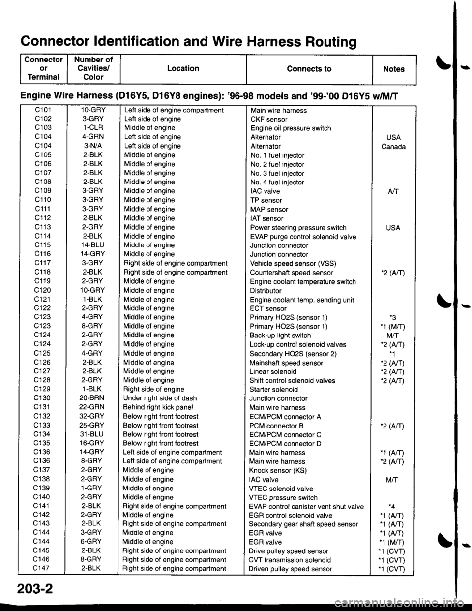
Connector ldentification and Wire Harness Routing
Connector
or
Terminal
Number ot
Cavities/
Golor
LocationConnects toNotes
Engine Wire Harness (Dl6Y5, D16Y8 engines): '96-98 models and '99;00 D16Y5 dM/T
c101
c102
c 103
c104
Q104
c105
c106
c107
cl 08
cl09
cl10
c1l1
cl'12
c113
c114
c'115
c116
c'117
c 118
c119
c120
c121
c122
c123
c123
c124
Q124
c125
c 126
c127
c128
c129
c130
c131
cl32
c 134
c135
c136
c137
c138
c139
c'140
c141
c142
c143
c144
c'|44
c145
c146
c147
1O-GRY
3.GRY
1-CLR
4-GRN
3-N/A
2-BLK
2-BLK
2-BLK
2-BLK
3-GRY
3-GRY
3-GRY
2.BLK
2.GRY
2-BLK
14-BLU
14-GRY
3.GRY
2-BLK
2-GRY
1O-GRY
1.BLK
2.GRY
4-GRY
8-GRY
2-GRY
2.GRY
4-GRY
2.BLK
2.BLK
2-GRY
1.BLK
2O.BRN
22.GRN
32.GRY
25.GRY
31-BLU
16.GRY
14-GRY
8.GRY
2-GFIY
2.GRY
1-GRY
2-GRY
2-BLK
2-GRY
2.BLK
3-GRY
6-GRY
2.BLK
8-GRY
2-BLK
Left side of engine compartment
Left side of engine
Middle of engineI att .i.la ^f an^i^6
Left side ot engine
Middle of engine
Middle of engine
Middle of engine
Middle of engine
Middle of engine
[,liddle of engine
Middle ot engine
Middle ot engine
Middle of engine
Middle of engine
Middle of engine
l\,liddle of engine
Right side of engine compartment
Right side of engine compartment
Middle ot engine
Middle of engine
Middle of engine
Middle of engine
l\,liddle of engine
Nliddle of engine
Middle ot engine
Middle of engine
Middle ot engine
Middle of engine
Middle of engine
Nliddle of engine
Right side of engine
Under right side of dash
Behind right kick panel
Below right front footrest
Below right front footrest
Below right front footrest
Below right front tootrest
Left side ot engine compartment
Left side of engine compartment
Middle of engine
liliddle ot engine
Middle of engine
Nriddle ol engine
Right side of engine compartment
Middle ol engine
Right side of engine compartment
Middle of engine
N,liddle of engine
Right side of engine compartment
Right side of engine compartment
Bight side of engine compartment
Main wire harness
CKF sensor
Engine oil pressure switch
Alternator
Alternator
No. 1 fuel injector
No. 2 fuel injector
No. 3 fuel injector
No.4 fuel injector
IAC valve
TP sensor
MAP sensor
IAT sensor
Power steering pressure switch
EVAP purge control sol€noid valve
Junction connector
Junction connector
Vehicle speed sensor (VSS)
Countershatt speed sensor
Engine coolant temperature switch
Distributor
Engine coolant temp. sending unit
ECT sensor
Primary HO2S (sensor '1)
Primary HO2S (sensor '1)
Back-up light switch
Lock-up control solenoid valves
Secondary HO2S (sensor 2)
lvlainshafl speed sensor
Lanear solenoid
Shift control solenoid valves
Starter solenoid
Junction connector
Main wire harness
ECM/PCM connector A
PCM connector B
ECM/PCNI connector C
ECM/PCl\,,| connector D
Main wire harness
Maln wire harness
Knock sensor (KS)
IAC valve
VTEC solenoid valve
VTEC pressure switch
EVAP control canister vent shut valv€
EGR control solenoid valve
Secondary gear shatt speed sensor
EGR valve
EGR valve
Drive pulley speed sensor
CVT transmission solenoid
Driven pulley speed sensor
USA
Canada
AlT
USA
'2( tr\
'3
-1 (M/r)
t\4/T'2 (Anl'1
'2 (An)'2 (Nr)'2 (AtT)
'2 (Atr)
-1 (An)-2( fi|
M/T
.1 (Arr).1 (A,T)"1 (A/r)-1 (M/r).1 (CVT),1 (cw)'1 (CVT)
203-2