Cvt transmission HONDA CIVIC 1998 6.G Owner's Guide
[x] Cancel search | Manufacturer: HONDA, Model Year: 1998, Model line: CIVIC, Model: HONDA CIVIC 1998 6.GPages: 2189, PDF Size: 69.39 MB
Page 1817 of 2189

Contents
How to Use This Manual ICircuit Schematics (see Circuit Index)Fuse/Relaylnformation 6Ground-to-Componentslndex 6-6ComponentLocationPhotooraohs 201Conriector Views 202
Circuit Index
Accessory power socket 155Air conditionerAir delivery'96198 models 61'99-'00 models 61-2Blower controls'96198 models 60'99100 models 60-1Compressor controls 62Fans 63Anti-lock brake system (ABS) 44A/T gear position indicatorCVT 89All except CVT 89-1Automatic transmission controlsAll '96-'98 models except CVT and GX 39All '99100 models except CVT 39-8All GX models 39-8'96-'�98 CVT 39-4'99100 cw 39-12Back-up lightsCoupe and Sedan 110Hatchback l'10-1Brake lightsAll Coupes and'96-'98 Sedans 110-15'99-'00 Sedans 110-16Hatchback 110-17Brake system indicator light'96198 models 7'1'99100 models 71-1Ceiling light 114-3Charging system 22Condenser fan 63Console lights 114Cruise control 34Dash lights 114Daytime running lights 110- 13Engine coolant temperature gauge 81-1Fog lights 110-10Front parking lights 110-2Fuel gauge 81-1Fuse/relay boxUnder-dash 6Under-hood 6-4Underhood ABS 6-3Gauges 81Ground distribution 14Ground-to-Componentslndex 6-6Hazard warning lightsAll except '99100 Sedans 110-6'99100 Sedans 110-8Headlights 110-12Headlight switch 100Heater - See Air ConditionerHorn'96197 models 40'98 model 40-1'99100 models 40-2lgnition key reminder 73lgnition systemAll '96198 models except Dl685 20All '99100 models except D16Y5 with Mn 2O-2All D1685 engines 20-2'99-'00 D 16Y5 with M/T 20
lndicators 80Integrated control unit 70lnterlock systemAll except'96J98 CVT 138'96198CVT 138-1License plate lightsAll Coupes and '96-'98 Sedans I l0-3'99100 Sedans 1 10-4Hatchback 110-5Low fuel indicator light 74Moonrool'96197 models |22'98-'00 models 122-1Odometer 81Oil pressure indicator light 80-3Power distributionBattery to ignition switch, fuses, and relaysFuses to relays and components 10-2Power door locksAll models without keyless entry 130'96-'98 models with keyless entry 130-2'99100 models with keyless entry 130-12Power mirrorsWithout detogger 141With defogger '141-2
Power windows 120Programmed fuel injection system (PGNr-Fl)All '96-98 models except D1685 23All '99-'00 models except D16Y5with M/T and D1685 24All D1685 engines 25'99100 D16Y5 with M/T 23Radiator fan 63Rear window defogger'96-,98 models 64'99100 models 64-1Seat belt reminder 73Security system'96.'98 USA HX, LX, EX 133'96-'98 Canada EX, Si 133'99TOO USA HX, LX, EX, DX.V Si 133-4'99100 Canada EX, Si 133-4All CX and DX models 133-8Speedometer 81Starting systemA./T (All except Dl685) 21A"/r (D16Bs) 21-1Manualtransmission 21-2Slereo sound system 150Supplemental rastraint system (SRS) 47Tachometer 81TailliqhtsAllboupes and'96-'98 Sedans 110-3'99100 Sedans 1 10-4Hatchback 110-5Trunk light 114-3Turn signal lightsAll except'99100 Sedans 110-6'99-'00 Sedans 1 10-8Vehicle speed sensor (VSS) 33Wiper/washerFront 91Rear 92
10
Page 1840 of 2189

Ground-to-Components I ndex
f.,lONOTE: All ground wires are BLK unless otherwise noted.
GroundPageComponents or Circuit Grounded
Battery (BLKYEL)
Steering pump bracket
t+-rg ITransmission housing
l
G101
(-1)
G101
(-2)
14-2
and
14-3
ano
14-1
Powertrain or engine control module (PG1 and pG2 are BLK: LG1 and LG2 are
BRN/BLK), EGR control solenoid valve (CW, EGR valve and lift sensor (Dt6yS enginewith M,/T), Engine coolant temperature switch, pGM-Fl main relay, power steeringpressure switch (USA), Primary HO2S (D16Y5 engine with l\/,/T), Vehicle speed sensor,VTEC pressure switch (D16Y5/D16Y8 engines), CKF sensor (BRN/BLK), Transmission
control module (CYf) (Pc1 is BLK: LG1 is BRN/BLK)
Shielding betvveen the PCM or ECM and these components (all have BRN/BLK wires):
CKF sensor, TDC/CKP/CYP sensor. Primary and secondary heated oxygen sensors.
Knock sensor (CWDl6YB engine), Mainshaft speed sensor (AiT except CVT),
I Countershaft speed sensor (A/T except CVf)
Shielding between the TCM and these components (CVT) (all have BRN/BLK wires):
Drive pulley speed sensor, Driven pulley speed sensor, Secondary gear shaft
speed sensor
Powertrain or engine control module (PG1 and pG2 are BLK; LG1 and LGz are
BRN/BLK), EGR control solenoid valve (D16Y5 engine), EGR valve (Dt685), Engine
coolant temperature switch, Fuel pressure regulator shut-off solenoid valve (D1685),
PGM-FI main relay, Power steering pressure switch (USA), Vehicle speed sensor, VTECpressure switch (All except D16Y7 engine), CKF sensor (A
except 81642) (BRN/BLK)
Shielding between the PCM or ECM and these components (all have BRN/BLK wires):
CKF sensor, TDC/CKP/CYP sensor, Primary and secondary heated oxygen sensors,
Knock sensor (All except D16Y7 engine), i/ainshaft speed sensor (Arf except CW),
Countershaft speed sensor (A,/T except CVf), Drive pulley speed sensor (CW), Drivenpulley speed sensor (CVT), Secondary gear shaft speed sensor (CVf)
I Badiator fan motor, Right front parking/turn signat tight, Right headtight
G20214-4I Cruise control actuator, Left front parking/turn signal lights, Left headlight, Rear window
I washer motor, Windshield washer motor, Washer fluid level switch (,99-'00 Canada)
G401| +-o
and
14-7
Accessory power socket, Brake fluid level switch, Clutch interlock switch (M/T), Clutchswitch (lillT with cruise/D16Y5 engine with MfD, Combination wiper switch (Z wires),
Cruise control main switch, Cruise control unit, Dash lights brightness controller, Data
link connector, Daytime running lights control unit (Canada), Gauge assembly, Horn('96-'97 models), Integrated control unit, Interlock control unit (ArI), Keyless door lock
control unit ('99-'00 models with keyless), Moonroof close and open relays, Moonroof
switch, Park pin switch (A/r), Power window relay, Rear window defogger relay, Rear
window defogger switch ('96-'98 models), Steering lock, Stereo radio tuner (,96-,98
USA: LX, EX, and HX), Turn signal/hazard relay, Windshield wiper motor.....plus
everything grounded through G402
6-6
Page 1846 of 2189
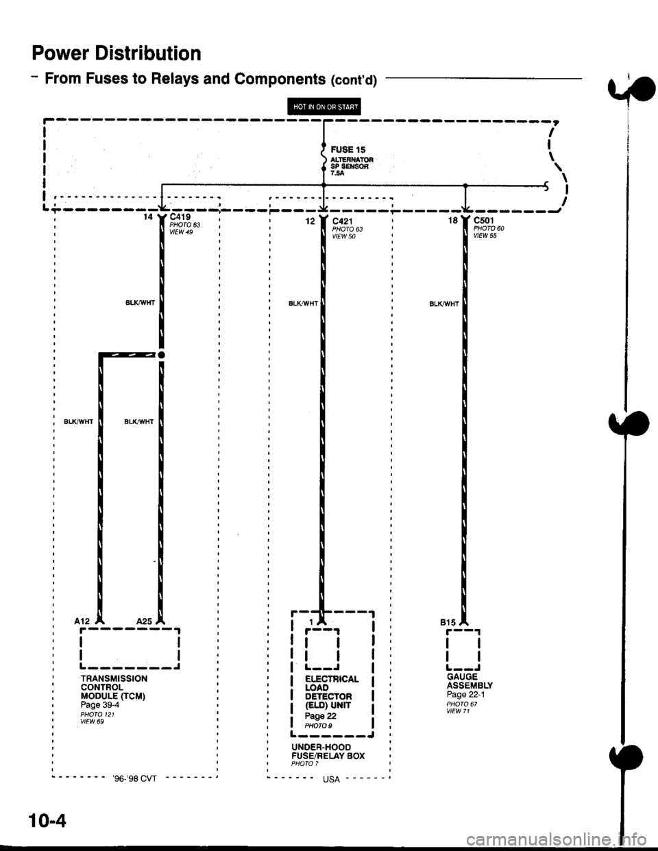
Power Distribution
- From Fuses to Relays and Components (contd)
FUSE 15AIITIFIIATORsP iE soa754
J-l
c4t912 I C421PHO|O 63virtu is-- : : I lj;:o,19^63
l,lll,nl
tl
i ! [8ig*'"*: : LOAD, I DETECTOR, I GLD} UI{17' | (ELDI u
: i Page 22
I
I
\
VEW 5A
{)
I
L-------J
TRANSMISSIONCONTROLMODULE [rCM]Page 39-4
vtEw 69
815
tl
tl
GAUGEASSEMBLYPage 22-1
, a PHO|O S
, UNDER-HOOD' FUSE/RELAY BOXI PHO|O 7
- '96-'�98 CVT
10-4
Page 1983 of 2189
A/T Gear Position Indicator (conrd)
- How the Circuit Works
With the ignition switch in ON (ll) or START (lll),
voltage is applied to the A,/T gear position indicator.
The A,/T gear position switch provides a ground for
each position. As an input is grounded, its indicator
light comes on. lf you select R, for example, ground
will be provided to the input of the A,/T gear position
indicato( and the R indicator will come on.
With the headlight switch in PARK or HEAD, voltage
is applied to the RED/BLK wire terminal. This
changes the indicator panel illumination from fixed
to controlled by the dash lights dimmer input
through the RED wire.
When the powertrain (all except '96-'98 CVT) or
transmission ('96198 CVT) control module (PCM or
TCM) detects an abnormality in the automatic
transmission control system, or when you request
diagnostic trouble codes through the service check
connector, the PCM or TCM will make the D4 (D for
CVT) indicator light blink.
Refer to the Service Manual (Section 14,
Automatic Transmission) for specific tests or
troubleshooting procedures.
\ia
89-2
Page 2100 of 2189

115. Left Side of Trunk Lid (except '99-'00 Sedan)118. Left Rear of Trunk/Cargo Area (except '99-'00 Sed.)b
\
116. Center of Trunk Lid119. Top of Transmission (CVT)
117. Rear Spoiler on Trunk Lid120. Right Side Rear of Engine Compartment (CVT)
L
ffi=
201 -19
Page 2101 of 2189

Gomponent Location
121. Behind Left Kick Panel ('96-'98 CVT)\124. Rear of Engine Compartment (CVT)
TRANSMISSIONCONTROL MODULE(rcM)
122. Right Side Lower Engine Compartment (CVT)125. Behind Right Side of Dash Panel
\
123. Right Front of Engine (CVT)126. Underside of Hatch Lid
k
2A1-20
\
Page 2132 of 2189
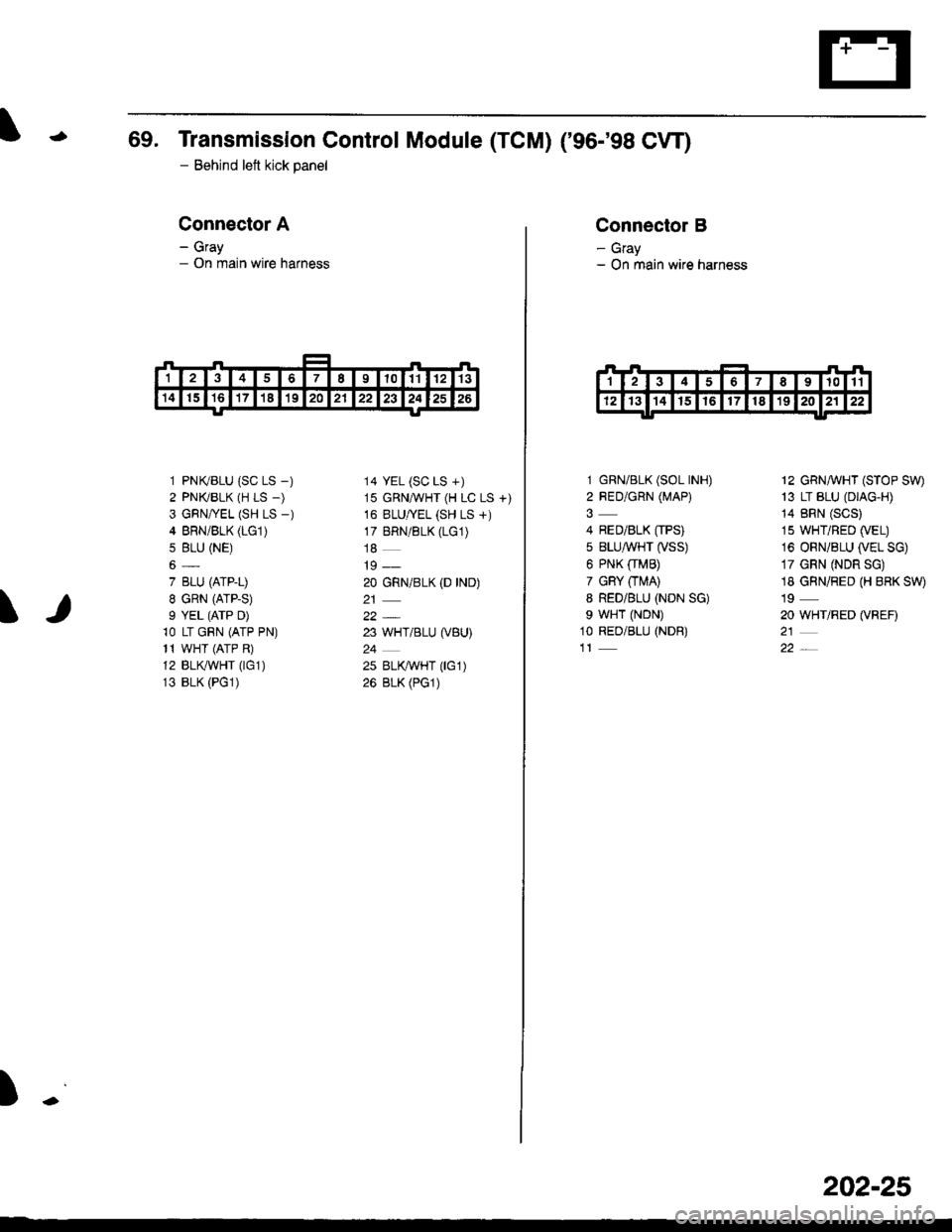
-69. Transmission Control Module (TCM) ('96-'98 CVT)
- Behind left kick panel
Connector A
- Gray- On main wire harness
\
1 PNI(BLU (SC LS -)
2 PN|(BLK (H LS -)
3 GRN/YEL (SH LS _)
4 BRN/BrK (LG1)
5 BLU (NE)
6-
7 BLU (ATP-L)
I GRN (ATP-S)
9 YEL (ATP D)
1O LT GRN (ATP PN)
11 WHT (ATP R)
12 BL(WHr (rG1)
13 BLK (PG1)
14 YEL (SC LS +)
15 GRNMHI (H LC LS +)
16 BLU/YEL (SH LS +)
17 BRN/BLK (LG1)
18
19 _
20 GRN/BLK (D IND)
23 WHT/BLU ryBU)24
2s BLI(WHT (rG1)
26 BLK (PG1)
)
Connector B
- Gray- On main wire harness
1 GRN/BLK (SOL rNH)
2 RED/GRN (MAP)
4 RED/BLK |rPS)5 BLUMHT (VSS)
6 PNK [rMB)7 GRY rrMA)8 RED/BLU (NDN SG)
9 WHT (NDN)
1O RED/BLU (NDR)
12 GRNAVHT (STOP SVV)
13 LT BLU (DIAG-H)
14 BRN (SCS)
15 WHT/RED (VEL)
16 ORN/BLU (vEr SG)
17 GRN (NDR SG)
18 GRN/RED (H BRK SW)
19
20 WHT/RED (VREF)
202-25
Page 2143 of 2189
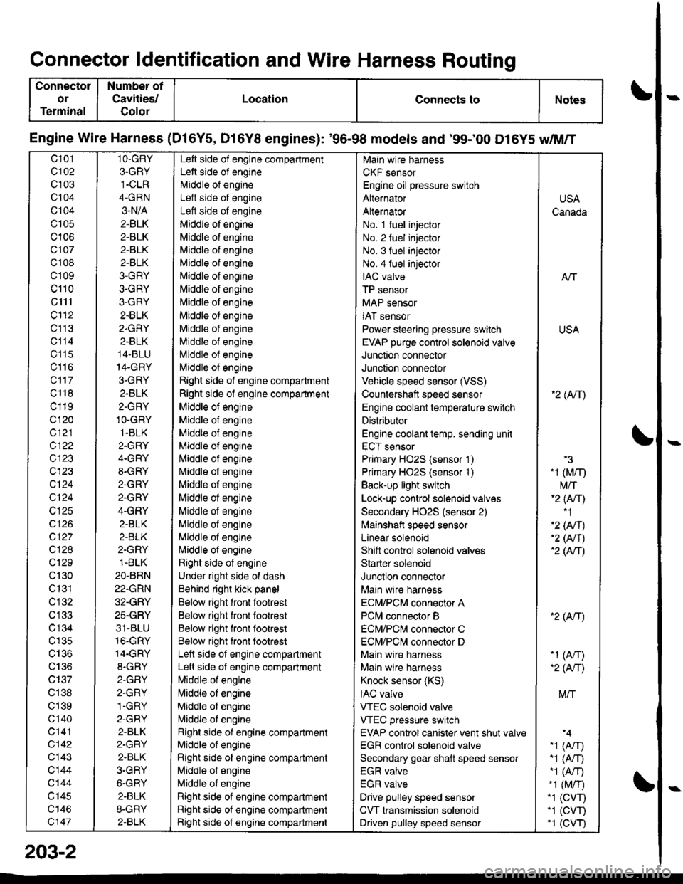
Connector ldentification and Wire Harness Routing
Connector
or
Terminal
Number ot
Cavities/
Golor
LocationConnects toNotes
Engine Wire Harness (Dl6Y5, D16Y8 engines): '96-98 models and '99;00 D16Y5 dM/T
c101
c102
c 103
c104
Q104
c105
c106
c107
cl 08
cl09
cl10
c1l1
cl'12
c113
c114
c'115
c116
c'117
c 118
c119
c120
c121
c122
c123
c123
c124
Q124
c125
c 126
c127
c128
c129
c130
c131
cl32
c 134
c135
c136
c137
c138
c139
c'140
c141
c142
c143
c144
c'|44
c145
c146
c147
1O-GRY
3.GRY
1-CLR
4-GRN
3-N/A
2-BLK
2-BLK
2-BLK
2-BLK
3-GRY
3-GRY
3-GRY
2.BLK
2.GRY
2-BLK
14-BLU
14-GRY
3.GRY
2-BLK
2-GRY
1O-GRY
1.BLK
2.GRY
4-GRY
8-GRY
2-GRY
2.GRY
4-GRY
2.BLK
2.BLK
2-GRY
1.BLK
2O.BRN
22.GRN
32.GRY
25.GRY
31-BLU
16.GRY
14-GRY
8.GRY
2-GFIY
2.GRY
1-GRY
2-GRY
2-BLK
2-GRY
2.BLK
3-GRY
6-GRY
2.BLK
8-GRY
2-BLK
Left side of engine compartment
Left side of engine
Middle of engineI att .i.la ^f an^i^6
Left side ot engine
Middle of engine
Middle of engine
Middle of engine
Middle of engine
Middle of engine
[,liddle of engine
Middle ot engine
Middle ot engine
Middle of engine
Middle of engine
Middle of engine
l\,liddle of engine
Right side of engine compartment
Right side of engine compartment
Middle ot engine
Middle of engine
Middle of engine
Middle of engine
l\,liddle of engine
Nliddle of engine
Middle ot engine
Middle of engine
Middle ot engine
Middle of engine
Middle of engine
Nliddle of engine
Right side of engine
Under right side of dash
Behind right kick panel
Below right front footrest
Below right front footrest
Below right front footrest
Below right front tootrest
Left side ot engine compartment
Left side of engine compartment
Middle of engine
liliddle ot engine
Middle of engine
Nriddle ol engine
Right side of engine compartment
Middle ol engine
Right side of engine compartment
Middle of engine
N,liddle of engine
Right side of engine compartment
Right side of engine compartment
Bight side of engine compartment
Main wire harness
CKF sensor
Engine oil pressure switch
Alternator
Alternator
No. 1 fuel injector
No. 2 fuel injector
No. 3 fuel injector
No.4 fuel injector
IAC valve
TP sensor
MAP sensor
IAT sensor
Power steering pressure switch
EVAP purge control sol€noid valve
Junction connector
Junction connector
Vehicle speed sensor (VSS)
Countershatt speed sensor
Engine coolant temperature switch
Distributor
Engine coolant temp. sending unit
ECT sensor
Primary HO2S (sensor '1)
Primary HO2S (sensor '1)
Back-up light switch
Lock-up control solenoid valves
Secondary HO2S (sensor 2)
lvlainshafl speed sensor
Lanear solenoid
Shift control solenoid valves
Starter solenoid
Junction connector
Main wire harness
ECM/PCM connector A
PCM connector B
ECM/PCNI connector C
ECM/PCl\,,| connector D
Main wire harness
Maln wire harness
Knock sensor (KS)
IAC valve
VTEC solenoid valve
VTEC pressure switch
EVAP control canister vent shut valv€
EGR control solenoid valve
Secondary gear shatt speed sensor
EGR valve
EGR valve
Drive pulley speed sensor
CVT transmission solenoid
Driven pulley speed sensor
USA
Canada
AlT
USA
'2( tr\
'3
-1 (M/r)
t\4/T'2 (Anl'1
'2 (An)'2 (Nr)'2 (AtT)
'2 (Atr)
-1 (An)-2( fi|
M/T
.1 (Arr).1 (A,T)"1 (A/r)-1 (M/r).1 (CVT),1 (cw)'1 (CVT)
203-2
Page 2145 of 2189
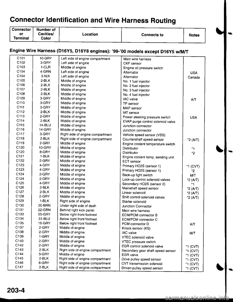
Connector ldentification and Wire Harness Routing
Connector
or
Terminal
Number of
Cavities/
Color
LocationConnects toNotes
Engine wire Harness (Dl6Y5, Dl6Y8 engines): '99-'00 models except D16y5 w/M/T
c 101
c102
c103
cl04
c104
c105
c106
c107
c108
c109
c110
c111
cl12
c1 13
c115
c117
c118
c119
c120
c120
c12'l
cl22
c123
c124
c124
c125
c126
c127
c128
c129
c130
c'131
c133
ct34
c 135
c137
c138
c139
c 140
c142
c143
c144
c'|45
c147
1O-GRY
3.GRY
1-CLR
4-GRN
3-N/A
2.BLK
2.BLK
2-BLK
2.BLK
3-GRY
3-GRY
3.GRY
2-BLK
2.GRY
2-BLK
14-BLU
14-GRY
3-GRY
2-BLK
2-GRY
1O-GRY
8.GRY,1-BLK
2.GRY
4.GRY
4.GRY
2.GRY
2.GRY
4.GRY
2.BLK
2-BLK
2-GRY
1-BLK
2O-BRN
22-GRN
25-GRY
31-BLU
16-GRY
2-GRY
2.GRY
1-GRY
2-GRY
2-GRY
2-BLK
3.GRY
2.BLK
8-GRY
2.BLK
Left side of engine compartment
Left side of engine
Middle of engine
Left side of engine
Left side of engine
Middle ot engine
Middle of engine
N,liddle of engine
l\4iddle of engine
Middle of engine
Niliddle of engine
N,,liddle of engine
Middle of engine
Middle of engine
Middle of engine
Middle of engine
Middle of engine
Rjght side of engine compartment
Right side of engine compartment
Middle of engine
Mlddle of engine
l\4iddle of engine
Middle of engine
Middle of engine
[iliddle of engine
lvliddle of engine
Middle of engine
Middle of engine
l\4iddle of engine
Middle ol engine
Middle of engine
N,liddle of engine
Right side of engine
Under right side of dash
Behind right kick panel
Below right front tootrest
Below right front footrest
Below right lront footrest
[iliddle of engine
l\,liddle of engine
Middle of engine
Middle of engine
L4iddle of engine
Right side of engine compartment
Middle of engine
Right side of engine compartment
Right side of engine compartment
Right side ot engine compartment
Main wire harness
CKF sensor
Engine oil pressure switch
Alternator
Alternator
No. 1 fuel injector
No. 2luel injector
No. 3 fuel injector
No.4 fuel injeclor
IAC valve
TP sensor
MAP sensor
IAT sensor
Power steering pressure switch
EVAP purge control solenoid valve
Junction connector
Junction connector
Vehicle speed sensor (VSS)
Countershaft speed sensor
Engine coolant temperature switch
Distributor
Distributor
Engine coolant temp. sending unit
ECT sensor
Primary HO2S (sensor 1)
Primary HO2S (sensor 1)
Back-up light switch
Lock-up control solenoid valves
Secondary HO2S (sensor 2)
Mainshait speed sensor
Linear solenoid
Shift control solenoid valves
Starter solenoid
Junction Connector
Main wire harness
ECN4/PCM connector B
ECM/PCM connector C
PCM connector D
Knock sensor (KS)
IAC valve
VTEC solenoid valve
VTEC pressure switch
EGR control solenoid valve
Secondary gear shaft speed sensor
EGR valve
Drive pulley speed sensor
CVT transmission solenoid
Driven pulley speed sensor
USA
Canada
ATT
USA
'2 (An\
'1
-1 (cw)
Mft'2 lNr)'1
'2 (Afil'2 (An)'2 (Anl
Atf
t\4/T
-1 (CVr)'1 (CVT).1 (CW)-1 (CVT)'1 (CVT).1 (cw
203-4