Thrust HONDA CIVIC 1998 6.G Owner's Guide
[x] Cancel search | Manufacturer: HONDA, Model Year: 1998, Model line: CIVIC, Model: HONDA CIVIC 1998 6.GPages: 2189, PDF Size: 69.39 MB
Page 669 of 2189
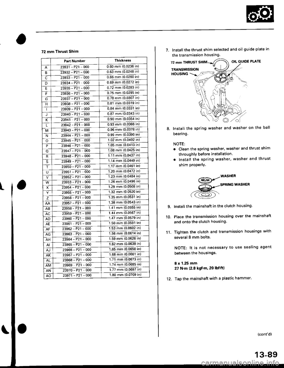
72 mm Thrust Shim
t
Part NumberThickness
23931 - P21 0000.60 mm {0.0236 in}
23932-P21 -0000.63 mm 10.0248 in)
c23933 P21 - 0000.66 mm (0.0260 in)
D23934 - P21 0000.69 mm (0.0272 in)
E2393s-P21-0000.72 mm (0.0283 in)
F23936-P21 -0000.75 mm (0.0295 in)
G23937 -P21-O000.78 mm (0.0307 in)
23938-P21 -0000.81 mm (0.0319 in)
23939-P21 -0000.84 mm (0.0331 in)
J23940-P21 -0000.87 mm (0.0343 in)
K23941 P21 - 0000.90 mm (0.0354 ini
L23942 - P21 0000.93 mm (0.0366 in)
23943-P21 -0000.96 mm 10.0378 in)
N23944 - P21 -0000.99 mm (0.0390 in)
o23945 - P21 0001.02 mm (0.0402 in)
P23946 - P21 0001.05 mm (0.0413 in)
o23947 - P2l 0001.08 mm (0.0425 in)
R23948-P21 -0001.'1 'l mm (0.0437 in)
S23949 - P21 0001.14 mm (0.0449 in)
T23950 - P21 0001.17 mm (0.0461 in)
23951 - P21 -0001.20 mm (0.0472 in)
23952 - P21 -0001.23 mm (0.0484 in)
23953-P21 -0001.26 mm (0.0496 in)
X23954-P21 -0001.29 mm (0.0508 in)
23955 - P21 -0001.32 mm (0.0520 in)
z23956-P21 -0001.35 mm (0.0531 in)
23957-P21 -0001.38 mm 10.0543 in)
AB23958 - P21 -0001.41 mm (0.0555 in)
AC23959 P21 - 0001.44 mm {0.0567 in)
23960 - P21 0001.47 mm (0.0579 in)
AE23961 - P21 -0001.50 mm {0.0591 in)
23962 P21 - 0001.53 mm {0.0602 in)
AG23963-P21 -0001.56 mm (0.0611in)
AH23964-P21 -0001.59 mm {0.0626 in)
23965-P21 -000'1.62 mm {0.0638 in)
23965-P21 - 0001.65 mm (0.0650 in)
AK23967-P21 -0001.68 mm {0.0661 in)
23968 - P21 -0001.71 mm 10.0673 in)
23969 P21 - 0001.74 mm {0.0685 in)
AN23970-P21 -0001.77 mm {0.0697 in)
AO23971 - P21 -0001.80 mm (0.0709 in)
7. lnstallthe thrust shim selected and oil guide plate in
the transmission housing.
72 mm THRUSTOIL GUIDE PLATE
TRANSMISSIONHOUSING
8. Install the spring washer and washer on the ball
beaflng.
NOTE:
. Clean the spring washer, washer and thrust shim
throughly before installation.
. Install the spring washer, washer and thrust
shim properlY.
-WASH€R-<]>-.-'
x -sPRtNG WASHER
-.-sK((9r'
lnstallthe mainshaft in the clutch housing.
Place the transmission housing over the mainshaft
and onto the clutch housing.
Tighten the clutch and transmission housings with
several 8 mm bolts.
NOTE: lt is not necessary to use sealing agent
between the housings.
8 x 1.25 mm
27 N.m (2.8 kgf.m. 20 lbf'ft)
Tap the mainshaft with a plastic hammer.
(cont'd)
9.
10.
'I l.
12.
13-89
Page 670 of 2189
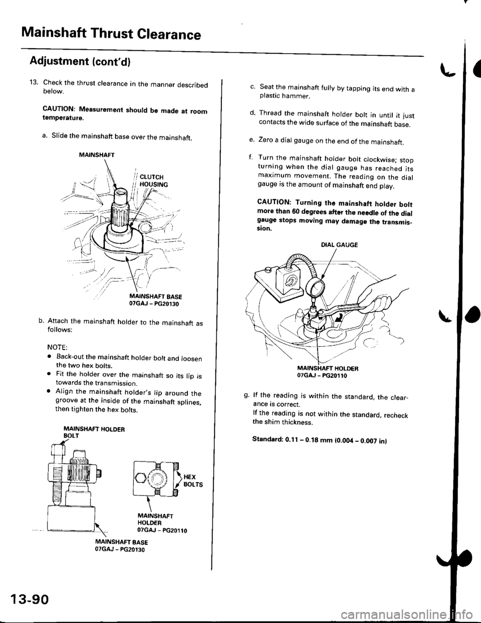
Mainshaft Thrust Clearance
Adjustment (cont'd)
13. Check the thrust clearance in the manner describedoetow.
CAUTION: Measuremenl should be made at roomtempetature.
a. Slide the mainshaft base over the mainshaft.
MAINSHAFT EASE07GAJ - PG20.130
b. Attach the mainshaft holder to the mainshaft asfollows:
NOTE:
. Back-out the mainshaft holder bolt and loosenthe two hex bolts.. Fit the holder over the mainshaft so its lip istowards the transmission.. AIign the mainshaft holder.s Iip around thegroove at the inside of the mainshaft splines,then tighten the hex bolts.
MAINSHAFT HOLOERBOLT
MAINSHAFT
[--F-e
l6fffi l
rx| - \-/ I/ Borrs
ff
MAINSHAFTHOLDER07GAJ - PG20110
MAINSHAFT BASE07GAJ - PG20130
13-90
c. Seat the mainshaft fully by tapping its end with aplastic hammer.
d. Thread the mainshaft holder bolt in untjl it justcontacts the wide surface of the mainshaft base.
e. Zero a dial gauge on the end ofthe mainshaft.
f. Turn the mainshaft holder bolt clockwise; stooturning when the dial gauge has reached itsmaxtmum movement. The reading on the dialgauge rs the amount of mainshaft end Dlav.
CAUTION: Turning tho mainshaft holder boltmore than 60 degrees after the needle of the dialg€uge stops moving may damage the transmis_ston.
07cAJ _ PG20110
g. lf the reading is within the standard, the clear-ance is correct.
lf the reading is not within the standard. recheckthe shim thickness.
Standard: 0.11 - O.18 mm {0.004 - 0.007 in}
DIAL GAUGE
Page 673 of 2189
tl
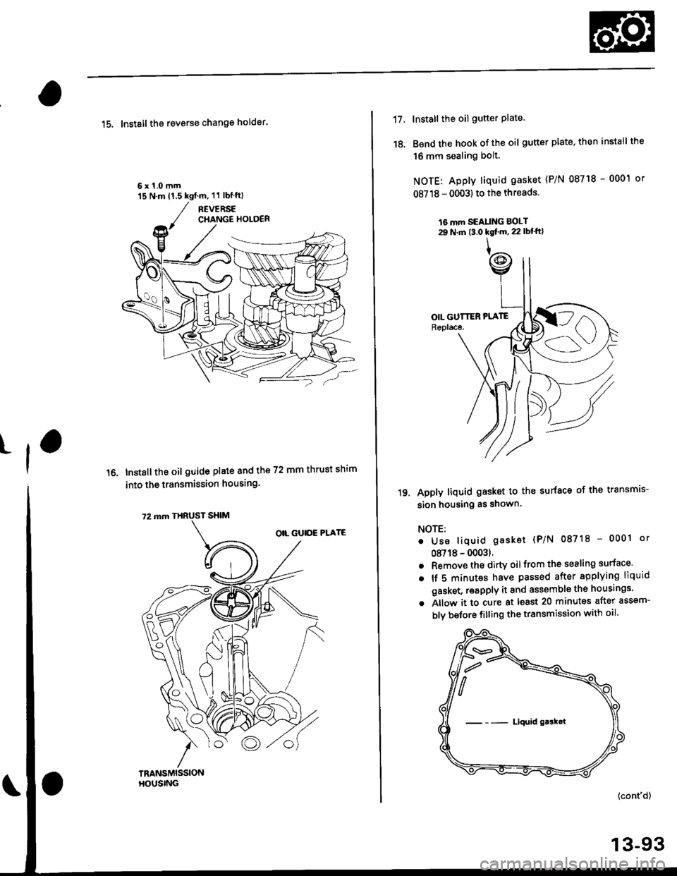
15. Install the reverse change holder.
6x1.0mm'15 N.m 11.5 kgim, 11 lblftl
Instsll the oil guide plate and the 72 mm thrust shim
into the transmission housing.
17.
18.
Install the oil gutter plate.
Bend the hook of the oil gutter plate, then install the
16 mm sealing bolt.
NOTE: Apply liquid gasket {P/N 08718 - 0001 or
08718 - 0003) to the threads.
16 mm SEALING BOLT29 N.m t3.0 kgl'm, 22 lbt'ft}
Apply liquid gasket to the surface of the transmis-
sion housing as shown'
NOTE:
. Use liquid gasket (P/N 087'18 - 0001 or
08718 - 00031.
. Remove the dirty oilfrom the sealing surface'
. lf 5 minut€s have passed after applying liquid
gasket, reapply it and assemble the housings'
. Allow it to cure at least 20 minutes after assem-
blv bsfore fitling the transmission with oil'
19.
(cont'd)
13-93
--- Liqui.l gask€t
Page 805 of 2189
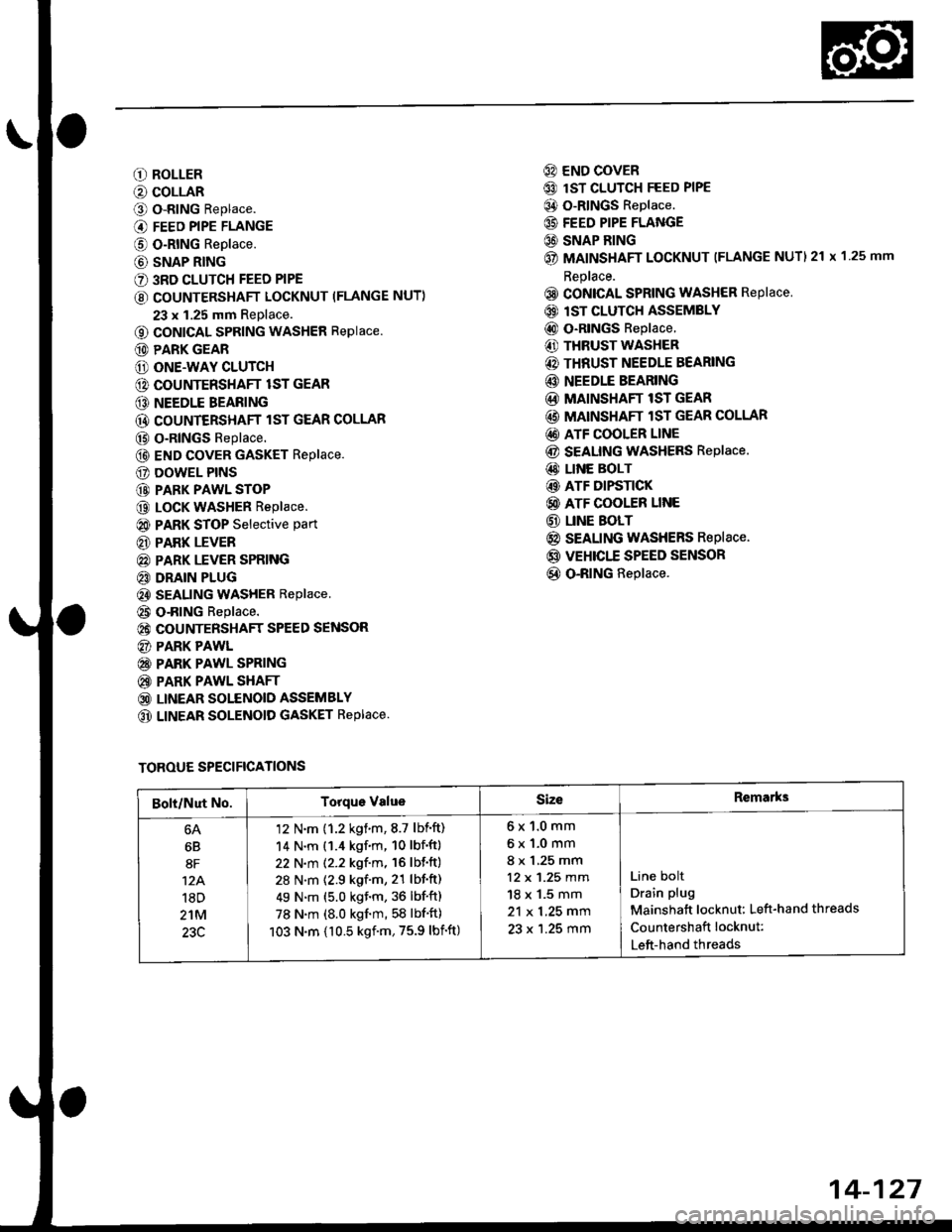
O ROLLER
O COLLAR
O o-RING Replace.
@ FEED PIPE FLANGE
@ O-RING Replace.
@ SNAP RING
€) 3RD CLUTCH FEED PIPE
€) COUNTERSHAFT LOCKNUT (FLANGE NUT)
23 x 1.25 mm Replace.
o coNlcAL SPRING WASHER Replace.
@ PARK GEAR
@ ONE.WAY CLUTCH
@ COUNTERSHAFT lST GEAR
@ NEEDLE BEARING
@ COUNTERSHAFT lST GEAR COLLAR
@ o-RlNGs Replace.
@ END covER GASKET Replace.
E) DOWEL PINS
@ PARK PAWL STOP
@ LocK WASHER Replace.
@ PARK STOP Selective part
€D PARK LEVER
@ PARK LEVER SPRING
€D DRAIN PLUG
€) SEALING WASHER Replace
@ o-RING Replace.
@ COUNTERSHAFT SPEED SENSOR
@) PARK PAWL
@ PARK PAWL SPRING
@ PARK PAWL SHAFT
@ LINEAR SOLENOID ASSEMBLY
@ LINEAR SOLENOID GASKET REPIACE.
@) END COVER
@ lsT CLUTCH FEED PIPE
@ O-RINGS Replace.
@ FEED PIPE FLANGE
C) SNAP BING
@ MAINSHAFT LOCKNUT (FLANGE NUTI 21 x 1 25 mm
Replace.
@ CONICAL SPRING WASHER RePlace
@) lST CLUTCH ASSEMBLY
@ o-RlNGs Replace.
€) THRUST WASHER
@) THRUST NEEDLE BEARING
@ NEEDLE BEARING
@ MAINSHAFT lST GEAR
@ MAINSHAFT lST GEAR COLLAR
@) ATF COOLER LINE
@ SEAUNG WASHERS Replace.
@ LINE BOLT
@ ATF DIFSTICK
@ ATF COOLER LINE
@ UNE BOLT
@ SEALING WASHERS Replace.
@ VEHICTT SPEED SENSOR
@ O-RING Replace.
TOROUE SPECIFICATIONS
Bolt/Nut No.Torque ValueSizeRemarks
6B
8F
12A.'l8D
2'tM
23C
'12 N'm (1.2 kgim,8.7 lbift)
14 N.m (1.4 kgf.m, 10 lbf'ft)
22 N.m (2.2 kgf.m, 16 lbf'ft)
28 N.m (2.9 kgf.m, 21 lbf'ft)
49 N.m (5.0 kgf.m, 36 lbf'ft)
78 N.m (8.0 kgf'm, 58 lbf'ft)
103 N.m {10.5 kgf'm,75.9 lbift)
6x1.0mm
6x1.0mm
8 x 1,25 mm
12 x 1.25 mm
18 x 1.5 mm
21 x 1.25 mm
23 x 1.25 mm
Line bolt
Drain plug
Mainshatt locknut: Left-hand threads
Countershaft locknut:
Left-hand threads
14-127
Page 807 of 2189
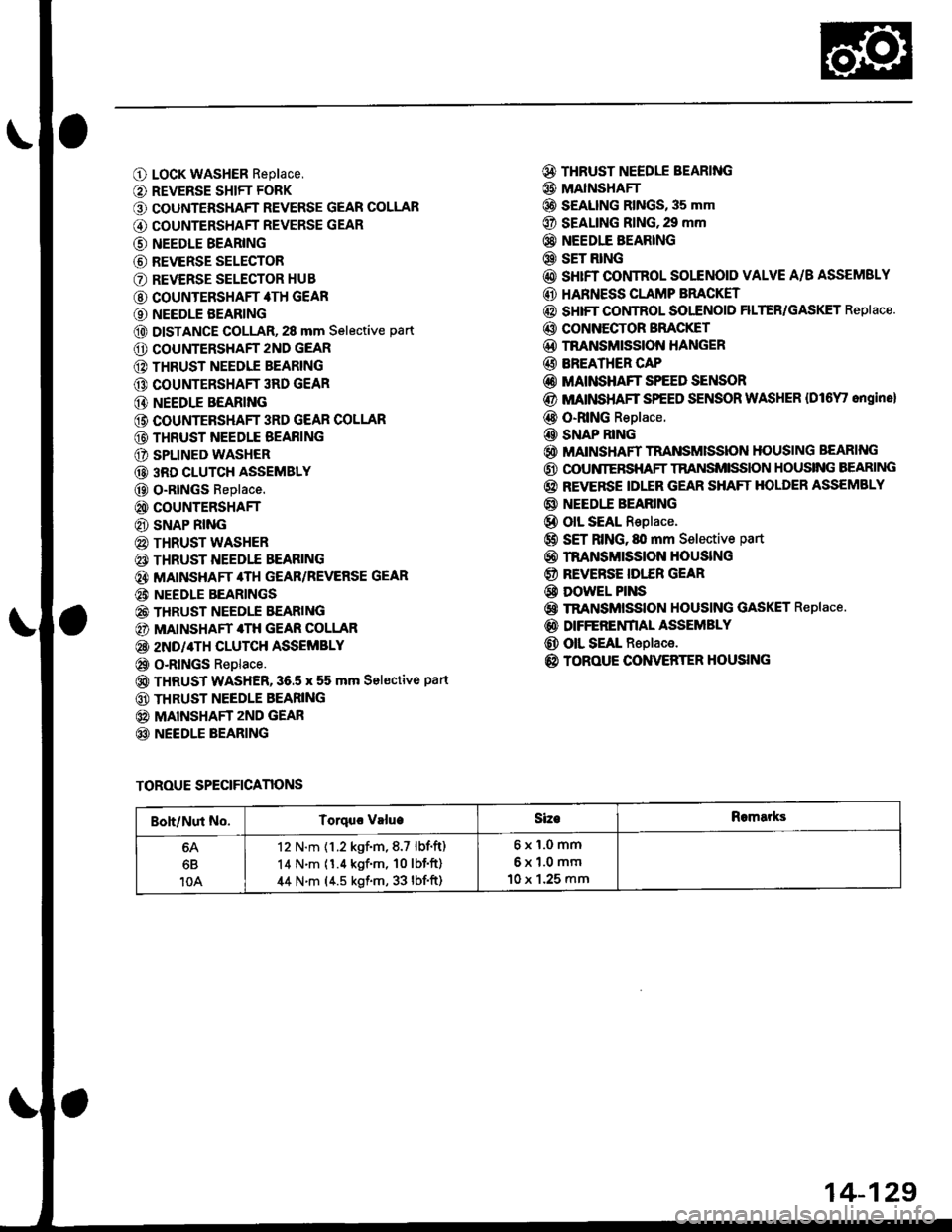
O LocK WASHER Replace,
O REVERSE SHIFT FORK
O COUNTERSHAFT REVERSE GEAR COLLAR
G) COUNTERSHAFT REVERSE GEAR
@ NEEDLE BEARING
@ REVERSE SELECTOR
O REVERSE SELECTOR HUB
@ COUNTERSHAFT 4TH GEAR
O NEEDLE BEARING
@ DISTANCE GOLLAR, 28 mm Selective part
O COUNTERSHAFT 2ND GEAR
@ THRUST NEEDIE BEARING
@ COUNTERSHAFT 3RD GEAR
@ NEEDLE BEARING
@ COUNTEBSHAFT 3RD GEAR COLLAR
@ THRUST NEEDLE BEAFING
O SPLINED WASHER
@ 3RD CLUTCH ASSEMBLY
@ O-RtNGs Replace.
@ COUNTERSHAFT
@ SNAP RING
@ THRUST WASHER
€) THRUST NEEDTE BEARING
@} MATNSHAFT 4TH GEAR/REVERSE GEAR
@i NEEDLE BEARINGS
@ THRUST NEEDLE EEARING
@) MAINSHAFT 4TH GEAR COLLAR
@ 2ND/4TH CLUTCH ASSEMBLY
@ o-RlNGs Replace.
@ THRUST WASHER,36.5 x 55 mm Sel€ctive part
@ THRUST NEEDLE BEARING
@ MAINSHAFT zND GEAR
@ NEEDLE BEARING
@ THRUST NEEDLE BEARING
@ MAINSHAFI
@ S€ALING RINGS, 35 mm
@ SEALING RING,29 mm
@} NEEDIE BEARING
@ SET RING
@ sHrFT CONTROL SOLENOID VALVE A/B ASSEMSLY
@ HARNESS CLAMP BRACKET
@ SHIFT COI,ITROL SOI"ENOID FILTER/GASKET Replace.
@ CONNECTOR BFACKET
@D TNANSMISSION HANGER
@ BREATHER CAP
@ MAINSHAFT SPEED SENSOR
@ MATNSHAFT SPEED SENSOR WASHER {Dl6Y' ongine}
@ O-RING Replace.
@ SNAP RING
@ MAINSHAFT TRANSMISSION HOUSING BEARING
@ OOUNIERSHAFT TRANSMISSION HOUSING BEARING
@ REVERSE IDLER GEAR SHAFT HOLDER ASSEMBLY
@ NEEDI.E BEARING
@ olL SEAL Replace.
@ SET RING, fll mm Selective part
@ rnANsMrssloN HouslNG
@ REVERSE IDI."ER GEAR
@ DowEL PINS
@ TRANSMISSION HOUSING GASKET Replace.
@ DIFFERENfIAL ASSEMBLY
@ OIL SEAL Replace.
@ TOROUE CONVERTER HOUSING
TOROUE SPECIFICANONS
Boh/Nut No.Torquo valueSizeRomarks
6B
10A
12 N.m {1.2 kgf.m,8.7 lbf.ft)
14 N.m (1.4 kgf'm, 10lbf'ft)
44 N.m (4.5 kgf.m, 33 lbf'ft)
6x1.0mm
6x1.0mm
10 x 1.25 mm
14-129
Page 819 of 2189
ATF Pump
Inspection
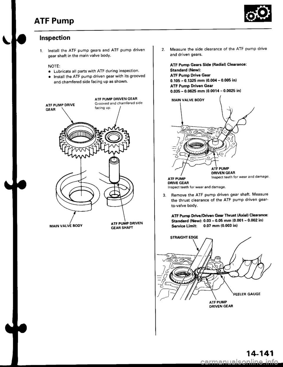
1. Install the ATF pump gears and ATF pump driven
gear shaft in the main valve body
NOTE:
. Lubricate all parts with ATF during inspection.
. Install the ATF pump driven gear with its grooved
and chamfered side facing up as shown.
MAIN VALVE BODY
ATF PUMP ORIVEN GEAR
Grooved and chamfe.ed side
2. Measure the side clearance of the ATF pump drave
and driven gears.
ATF Pump Gears Side {Radial) Clearance:
Standard (New):
ATF Pump Drive Gear
0.105 - 0.1325 mm {0.004 - 0.q)5 in}
ATF Pump Drivsn Gear
0.035 - 0.0625 mm (0.0014 - 0.0025 inl
MAIN VALVE SOOY
YZ]
o?
ATF PUMPDRIVE GEAR
ATF PUMPDRIVEN GEARInspect teeth for wear and damage
lnspect teeth for wear and damage.
3. Remove the ATF pump driven gear shaft. Measure
the thrust clearance of the ATF pump driven gear-
to-valve bodY.
ATF Pump Drive/Drivon Gear Thrust {Axial} Cloarance:
Standard (Now): 0.03 - 0.05 mm 10'001 - 0.002 inl
Sorvice Limit: 0.07 mm (0.003 in)
1+141
Page 826 of 2189
Mainshaft
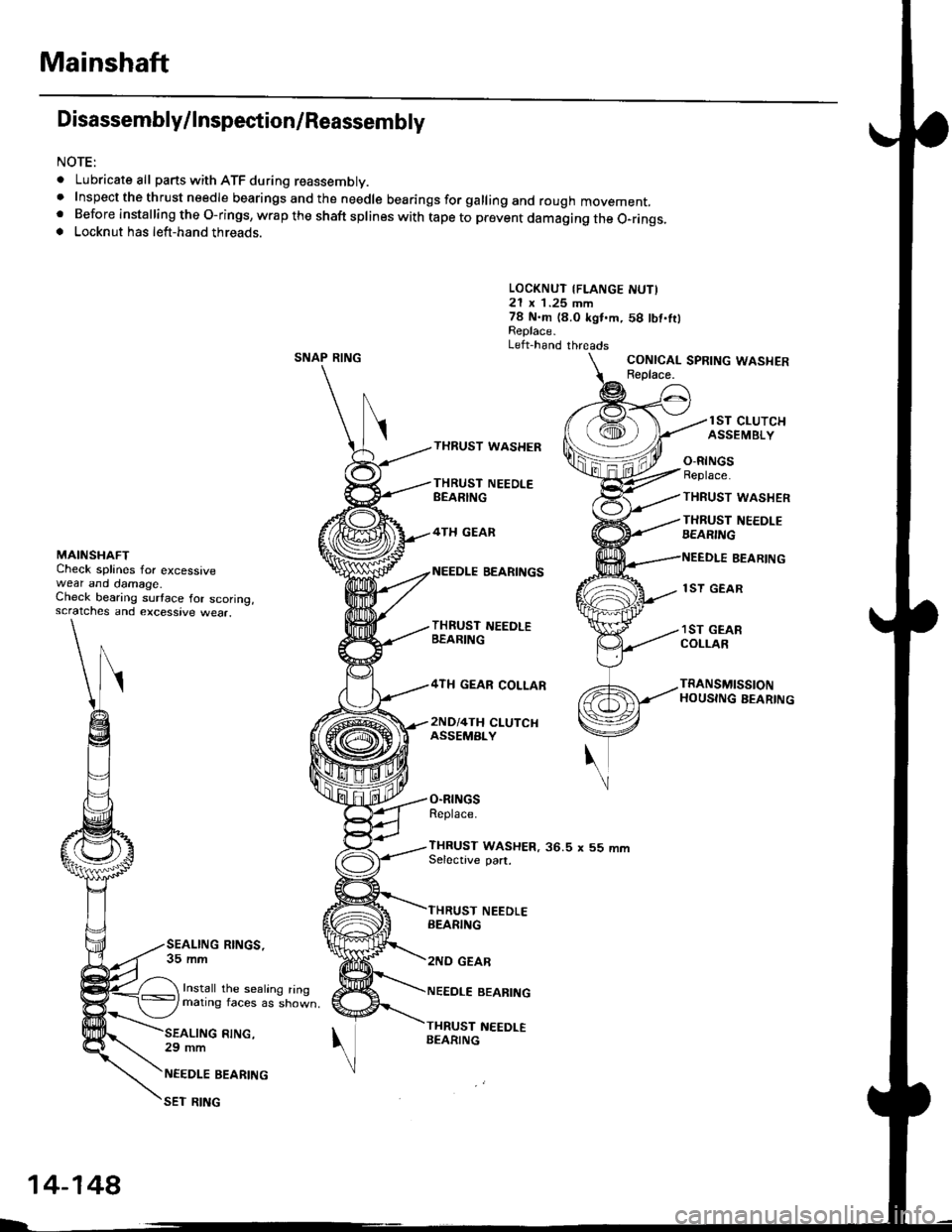
Disassembly/lnspestion/Reassembly
NOTE:
. Lubricate all parts with ATF during reassembly..Inspectthethrustneedlebearingsandtheneedlebearingsforgallingandroughmovement,
. Before installing the O-rings, wrap the shaft splines with tape to prevent damaging the O_rings.. Locknut has left-hand threads.
LOCKNUT {FLANGE NUTI21 x 1.25 mm78 N.m (8.0 kgl.m,58 lbt.fttReplace.Left-hand threadsSNAP RINGCONICAL SPRING WASHERReolace.
lST CLUTCHASSEMBLYTHRUST WASHER
THRUST NEEOI.EBEARING
4TH GEAN
O-RINGSReplace.
THRUST WASHER
THRUST NEEDLEBEARING
MAINSHAFTCheck splines for excessivewear and oamage.Check bearing surtace for scoring,scratches and excessive wear.
BEARINGBEARINGS
THRUST NEEDLEBEABING
4TH GEAR COLLAR
2ND/4TH CLUTCHASSEMBLY
THRUST NEEDLEEEARING
2NO GEAB
NEEDLE BEABING
THRUST NEEDLEBEARING
1ST GEAR
1ST GEARCOLLAR
TRANSMISSIONHOUSING BEARING
O-RINGSReplace.
THRUST WASHER, 36.5 x 55 mmSelective part.
SEALING RINGS,35 mm
Install the sealing ringmating faces as shown,
RING,29 mm
NEEDLE BEARING
SET RING
14-148
Page 827 of 2189
Inspection
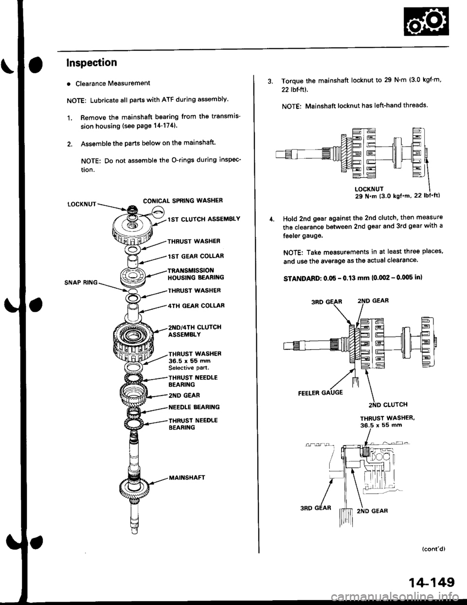
a Clearance Measurement
NOTE: Lubricate all parts with ATF during assembly.
1, Remove the mainshaft bearing from the transmis-
sion housing (see Page 14-1741.
2. Assemble ths parts below on the mainshaft.
NOTE: Do not assemble the O-rings during inspec-
tlon.
LOCKNUTCONICAL SPRIIIG WASHER
SNAP RING
lST CLUTCH ASSEMBLY
TXRUST WASHER
1ST GEAR COLLAR
TRA SMISSIONHOUSII{G BEARING
THRUST WASHER
4TI{ GEAR COLLAR
2ND/4TH CLUTCHASSEMBLY
THRUST WASHER36.5 x 55 mmSelective part.
THBUST NEEDLEBEARING
2ND GEAR
AEABII{G
IHRUST NEEDLEBEARING
MAINSHAFT
3. Torque the mainshaft locknut to 29 N'm (3.0 kgf'm,
22 tbt,ftl.
NOTE: Mainshaft locknut has left-hand threads.
29 N'm t3.0 kgl'm, 22 lbt'ft)
Hold 2nd gear against the 2nd clutch' then measure
the clearance between 2nd gear and 3rd gear with a
feeler gauge.
NOTE: Take measurements in at least three places,
and use the av€rage as the actual clearance'
STANDARD: 0.05 - 0.13 mm 10.002 - 0.005 in)
THRUST WASHER,36.5 x 55 mm
(cont'd)
1+149
Page 828 of 2189
Mainshaft
Inspection (cont'd)
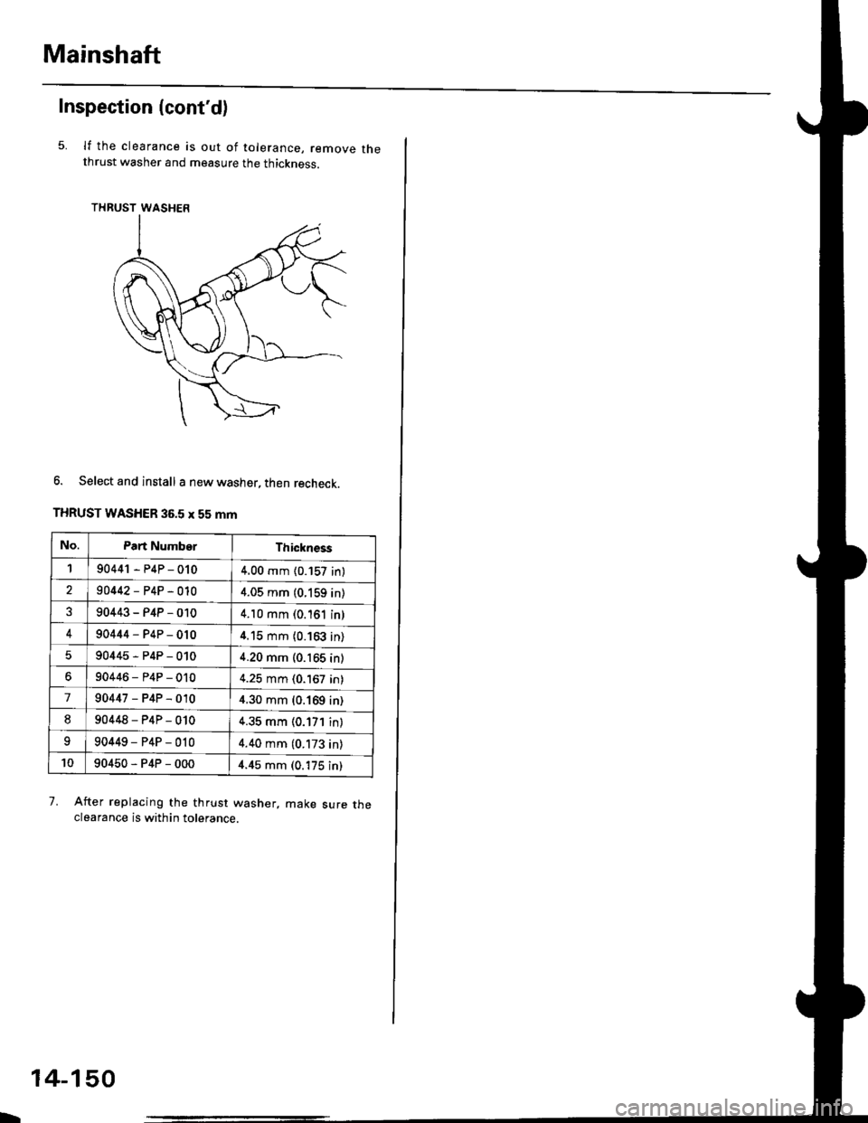
5.lf the clearance is out of tolerance, remove thethrust washer and measure the thickness.
THRUST WASHER
6. Select and install a new washer, then recheck.
THRUST WASHER 36.5 x 55 mm
After replacing the thrust washer, make sure theclearance is within tolerance.
7.
No.Part NumberThickness
190441 - P4P - 0104.00 mm (0.157 in)
90442-P4P-0104.05 mm (0.159 in)
90443-P4P-0104.10 mm (0.'161 in)
490444-P4P-0104.15 mm (0.163 in)
90445-P4P-0104.20 mm (0.165 in)
90446-P4P-0104.25 mm (0.167 in)
790447-P4P-0104.30 mm (0.169 in)
890448-P4P-0104.35 mm (0.171 in)
90449-P4P-0104.40 mm (0.173 in)
1090450-P4P-0004.45 mm (0.175 in)
b
14-150
Page 829 of 2189
Countershaft
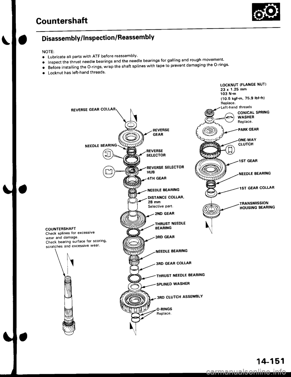
Disassembly/lnspection/Reassembly
NOTE:
. Lubricate all parts with ATF before reassembly'
. tnrp"",,n",t -"t needle bearings and the needle bearings for galling and rough movement'
. Before installing the O-rings. wrap the shaft splines with tape to prevent damaging the O-rings
. Locknut has left-hand threads
LOCKNUT (FLANGE NUT}
23 x 1.25 mm103 N.m
{10.5 kgf'm, 75.9 lbf'tt)
Replace.Left'handlhreads
CONTCAL SPRING
WASHERReplace.
GEAR
CLUTCH
1ST GEAR
BEARING
lST GEAR COLLAR
TRANSMISSIONHOUSING BEARING
REVERSE GEAR
NEEDLEBEARING
SELECTOR
SELECTOR
4TH GEAR
NEEDLE BEARING
DISTANCE COLLAS,
28 mmSelective pa .
COUNYERSHAFTCheck splines lor excesslve
wear and damage
2'{D GEAR
THRUST NEEDLEBEARING
3RD GEAB
NEEDLE BEARING
3RD GEAR COLLAR
THRUST NEEDLE EEARING
SPLINEO WASHER
3RD CLUTCH ASSEMBLY
Check bearing surface for scoring'
scratches and excessive wear'
Replace.
1+151