check engine HONDA CIVIC 1998 6.G Service Manual
[x] Cancel search | Manufacturer: HONDA, Model Year: 1998, Model line: CIVIC, Model: HONDA CIVIC 1998 6.GPages: 2189, PDF Size: 69.39 MB
Page 162 of 2189
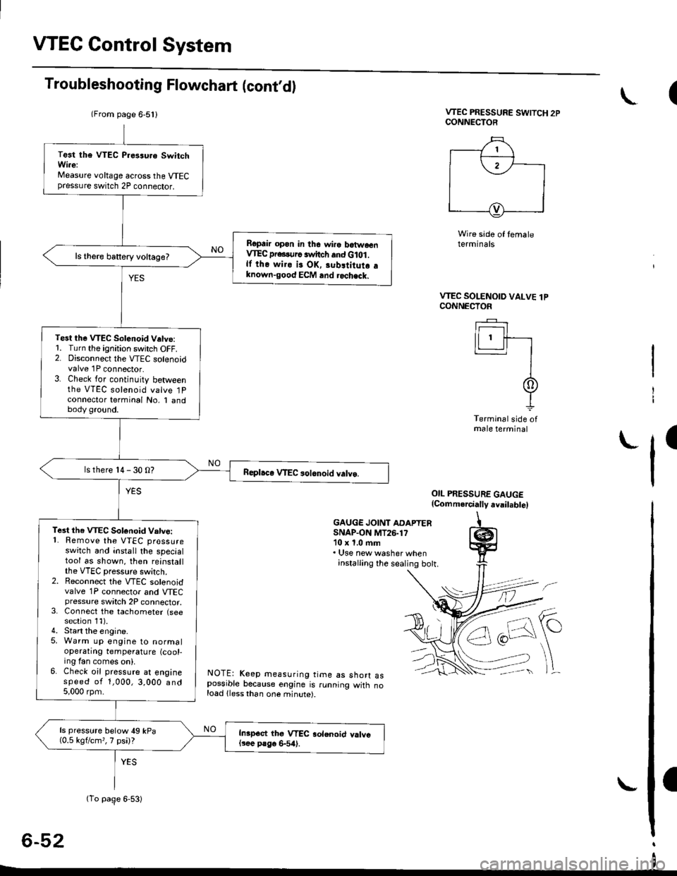
VTEC Control System
Troubleshooting Flowchart (cont,d)
VTEC PRESSURE SWITCH 2PCONNECTOR
Wire side of temaleterminals
OIL PRESSURE GAUGE(Comm.rcially avail.bte)
GAUGE JOINT ADAPTERSNAP.ON MT26.1710 x 1.0 ftm. Use new washer wheninstalling the sealing bott.
NOTE: Keep measuring time as shorr aspossible because engine is running witn noload lless than one minute).
6-52
(
VTEC SOLENOID VALVE lPCONNECTOF
Ir------r I
lLl.ll-r
II
It
Terminal side ofmale terminal
I
(From page 6-5l l
(To page 6-53)
Test tha VTEC P.es3uro SwitchWi.e:Measure voltage across the VTECpressure switch 2P connector.
Ropair opon in the wiro batwoenVIEC pr...urc switch and G lot .lf the wiro is OK, 3ubltitutr aknown-good ECM and rochack.
ls there battery voltage?
Test the VTEC Solenoid V.tve:1. Turn the ignition switch OFF.2. Disconnect the VTEC solenoidvalve 1P connector.3. Check for continuity betweenthe VTEC solenoid valve 1Pconnector terminal No, I andbody ground.
ls there 14 - 30 O?
Te3t the VTEC Sotonoid Vatve:'1. Remove the VTEC pressureswitch and install the specialtool as shown. then reinstallthe VTEC pressure switch.2. Reconnect the VTEC solenoidvalve 1P connector and VTECpressure switch 2P connector,3. Connect the tachometer (seesection 1l).4. Start the engine.5. Warm up engine to normaloperatrng temperature (cool-ing fan comes on).6. Check oil pressure at enginespeed of 1,000,3,000 and5,000 rpm.
ls pressure below 49 kPa(0.5 kgflcm,,7 psi)?Inipoct thg VTEC aolenoid valvel3ee P8go 6-54).
I
Page 163 of 2189
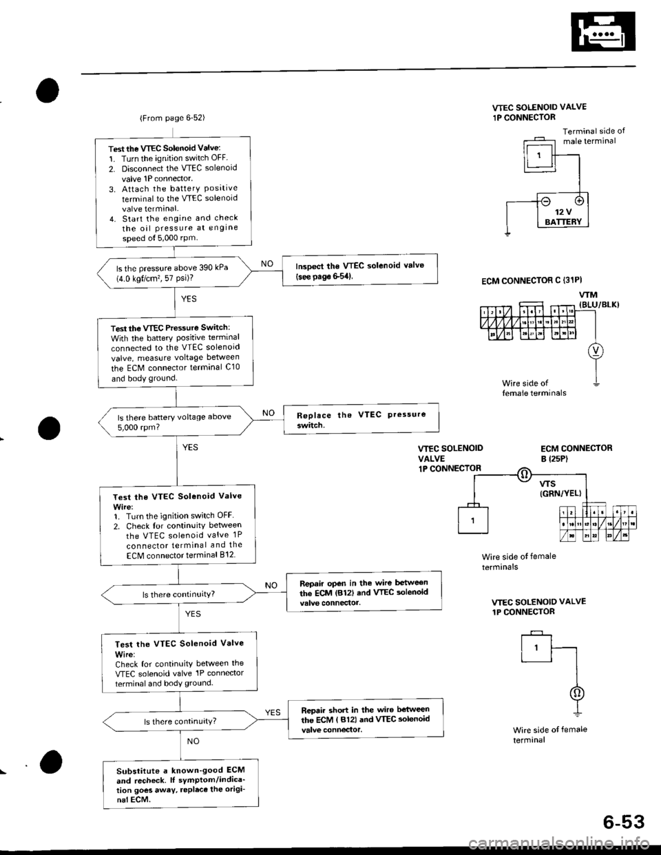
(From page 6-52)
Test the VTEC Solenoid Valve:
1. Turn the ignition switch OFF
2. Disconnect the VTEC solenoid
valve 1P connector,
3. Attach the batterY Posrtrveterminal to the VTEC solenoid
valve terminal.4. Start the engine and check
the oil Pressure at engine
speed ol5,000 rPm
lrcoect the VTEC solenoid valve(see page S54)ls the pressure above 390 kPa(4.0 kgt/cm?, 57 Psi)?
Test the VTEC Pressure Switch:
With the battery Positive terminal
connected to the VTEC solenoid
valve, measure voltage between
the ECM connector terminal C10
and body ground.
ls there battery voltage above
5,000 rpm?
Test the VTEC Solenoid Valve
Wire:1. Turn the ignition switch OFF
2. Check for continuitv between
the VTEC solenoid valve 1P
con nector terminal and the
ECM connector terminal 812
Repair open in the wire between
the ECM lB12| and VTEC aolenoid
Test lhe VTEC Solenoid Valve
Wire:Check for continuity between the
VTEC solenoid valve'lP connector
terminal and body ground.
Repair short in the wiro b€'tween
the ECM ( 812) and VTEC aolenoid
Substitute a known'good ECM
and recheck. lI sYmptom/indica'tion goes away. repleca the origi-
nal ECM.
VTEC SOLENOID VALVE
1P CONNECTOR
Terminal side ofmale terminal
VIEC SOLENOIDVALVE1P CONNECIOR
ECM CONNECTORB l2sP)
ECM CONNECTOR C (31PI
WM
Wire side ot female
termrnals
VTEC SOLENOID VALVE
1P CONNECTOR
I'ft
I
I
Wire side of female
termanal
6-53
Page 164 of 2189
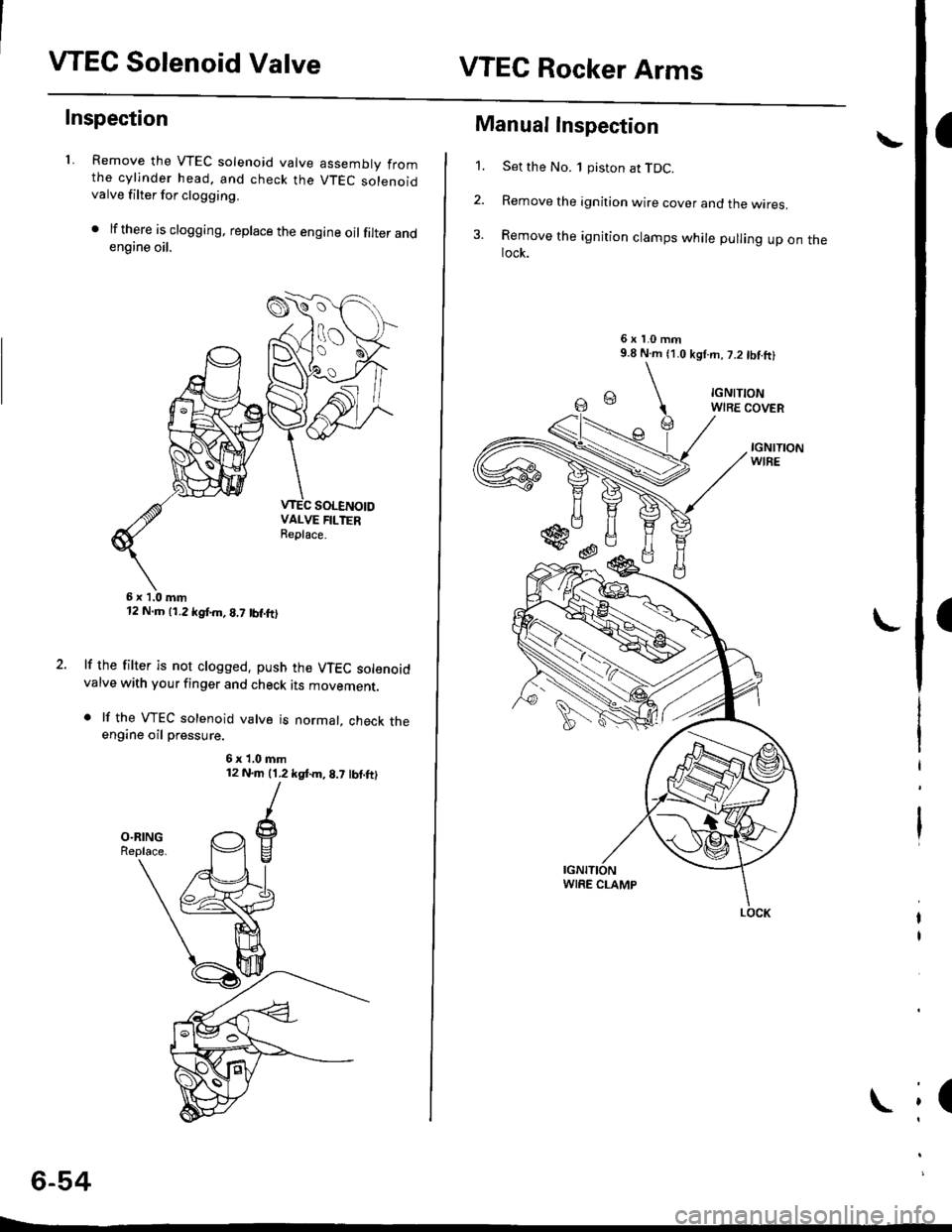
VTEC Solenoid ValveVTEC Rocker Arms
a
I
(
Inspection
1. Remove the VTEC solenoid valve assembly fromthe cylinder head. and check the VTEC solenoidvalve filter for clogging.
. lf there is clogging, replace the engine oilfilter andengine oil.
6x1.0mm12 N.m (1.2 kgf.m, B,7 tbf.ftl
lf the filter is not clogged. push the VTEC solenoidvalve with your finger and check its movemenr.
. lf the VTEC solenoid valve is normal, check theengine oil pressure.
6x1.0mm12 N.m (1.2 kgtm,8.7 lbt.ft)
6-54
L-
SOLENOID
Manual Inspection
1. Set the No. 1 piston at TDC.
2. Remove the ignition wire cover and the wires.
3. Remove the ignition clamps while pulling up on theIock.
6xl.0mm9.8 N.m (1.0 kgl.m, 7.2 tbtftl
IGNITIONWIRE COVER
IGNITIONWIRE
\
LOCK
Page 191 of 2189
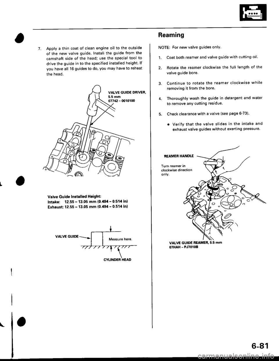
7. Apply a thin coat of clean engine oil to the outside
of the new valve guide. Install the guide from the
camshaft side of the head; use the special tool to
drive the guide in to the specified installed height. lf
you have all l6 guides to do, you may have to reheat
the head,
VALVE GUIDE DRIVER,5.5 mm077i12 - (x)l01(x)
tr A\
Valve Guide Installed Hoight:
lntake: 12.55 - 13.05 mm {0.,194 - 0.514 in)
Exhaust: 12.55 - 13.05 mm 10.494 - 0.51'l in)
VALVE GUIDE
\
Reaming
NOTE: For new valve guides onlY.
1. Coat both reamer and valve guide with cufting oil.
2. Rotate the reamer clockwise the full length of the
valve guide bore.
Continue to rotate the reamer clockwise while
removing it from the bore
Thoroughly wash the guide in detergent and water
to remove any cutting residue.
Check clearance with a valve lsee page 6-73)
. Verify that the valve slides in the intake and
exhaust valve guides without exertlng pressure.
REAMER HANDLE
Turn r6amer in
clockwise direction
a
VALVE GUIOE REAMER. 5.5 mm
OTHAH - PJTO1IIB
6-81
Page 196 of 2189
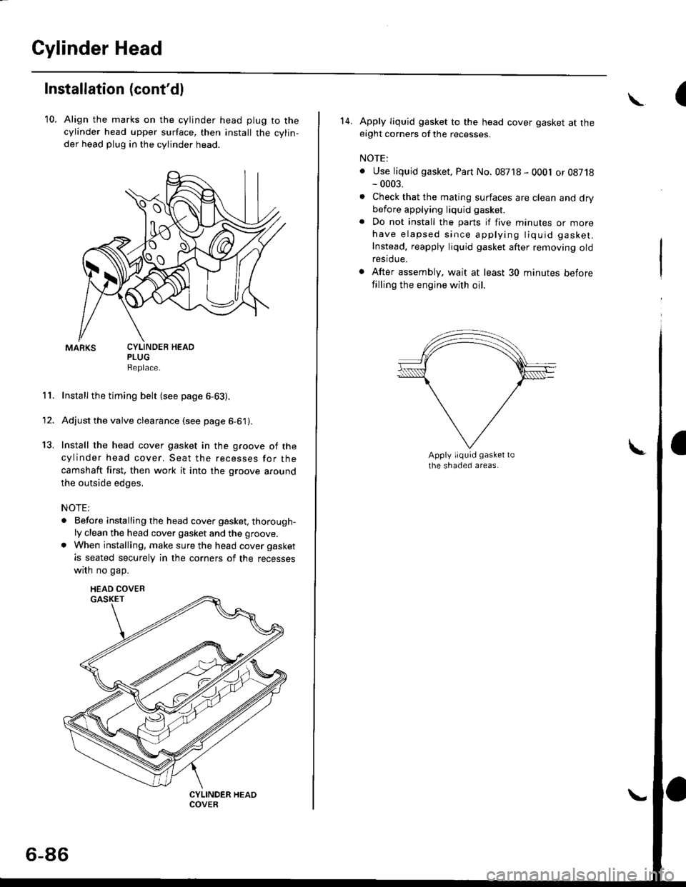
Cylinder Head
Installation (cont'dl
10. Align the marks on the cylinder head plug to thecylinder head upper surface, then install the cylin,
der head plug in the cylinder head.
PLUGReplace.
Install the timing belt (see page 6-63).
Adjust the valve clearance (see page 6-61).
Install the head cover gasket in the groove of the
cylinder head cover. Seat the recesses for the
camshaft first, then work it into the groove around
the outside edges,
NOTE:
. Before installing the head cover gasket, thorough-ly clean the head cover gasket and the groove.
. When installing, make sure the head cover gasket
is seated securely in the corners of the recesses
wrrn no gap.
11.
13.
1'
CYLINDEB HEAD
HEAD COVEB
6-86
(\
14. Apply liquid gasket to the head cover gasket at theeight corners of the recesses.
NOTE:
. Use liquid gasket, Part No. 08718 - 0001 or 08718- 0003.
. Check that the mating surfaces are clean and drybefore applying liquid gasket
. Do not install the parts if five minutes or morehave elapsed since applying tiquid gasket.
Instead, reapply liquid gasket after removing oldrestdue.
. After assembly. wait at least 30 minutes before
filling the engine with oil.
Page 197 of 2189
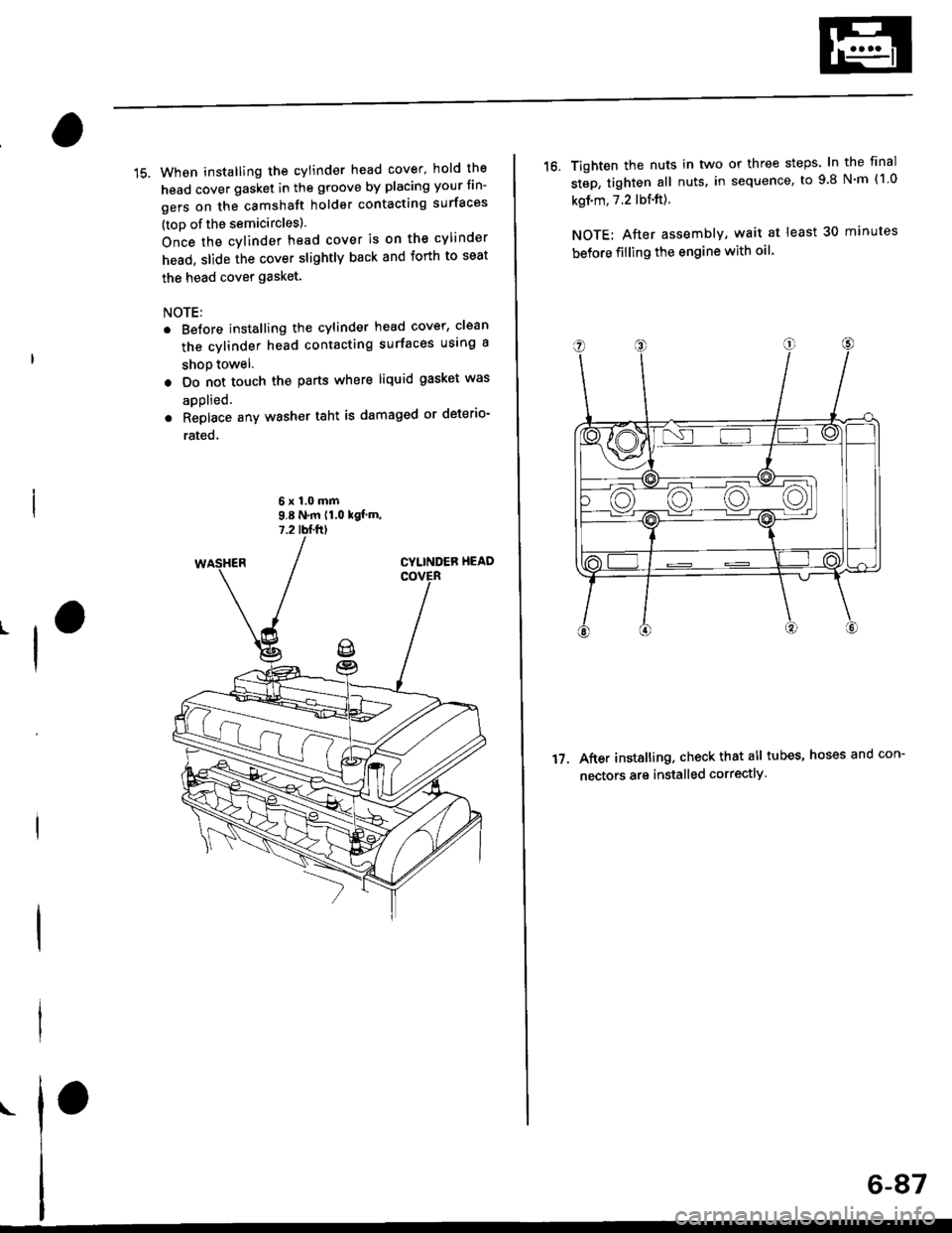
15. When installing the cylinder head cover, hold the
head cover gasket in the groove by placing your fin-
gers on the camshaft holder contacting surfaces
(toD of the semicircles).
Once the cylinder head cover is on the cylinder
head, slide the cover slightly back and forth to seat
the head cover gasket.
NOTE:
. Be{ore installing the cylinder head cover, clean
the cvlinder head contacting surfaces using a
shoP towel.
. Oo not touch the parts where liquid gasket was
applied.
. Replace any washer taht is damaged or deter'o-
rated.
t
\
6-A7
16. Tighten the nuts in two or three steps. In the final
step, tighten all nuts, in sequence, to 9 8 N'm {1 0
kgf.m, 7.2 lbf.ft).
NOTE: After assembly, wait at least 30 minutes
before filling the engine with oil.
After installing, check that all tubes' hoses and con-
nectors are installed correctly.17.
Page 200 of 2189
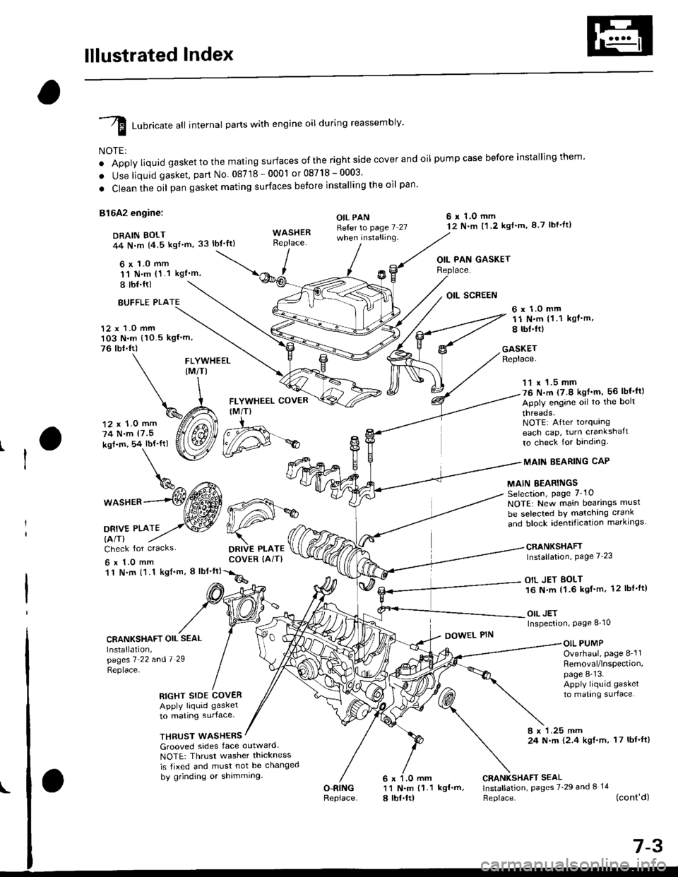
lllustrated Index
I runricate att internal parts with engine oil during reassembly'
NOTE:
o Apply liquid gaskettothe mating surfaces ofthe right side cover and oil pumpcase before installingthem'
. Use liquid gasket, part No 08718-0001 or08718-0003'
. Clean the oil pan gasket mating surfaces betore installing the oil pan
81642 engine:
DRAIN BOLT44 N,m {4.5 kgf'm,33 lbt'ft)
6 x 1.0 mm'11 N.m (1.1 kgI'm,
I tbl.ft)
OIL PANReter to page 7 27when installing.
6 r 1.O mm12 N.m t1.2 kgl'm, 8 7 lbf'lt)
OIL PAN GASKET
BUFFLE PLA
12 x 1.0 mm103 N.m {10.5 kgf'm,
76 tbr.ft)
6 x 1.0 mm11 N.m (1 .1 kgf.m,
8 tbI.fr)
GASKETReplace.FLYWHEEL(M/TI
12 x 1.0 mm
74 N.m (7.5
kof.m, 54 lbf'ft)
1^c{Eb\%^ t*^
*o"rr^--(Wffi
oa*,trto2,.w
FLYWHEEL COVER
IM/T)
DRIVE PLATECOVER (AiT)
11 x 1.5 mm76 N.m (7.9 kgf'm, 56 lbf'ft)
Apply engine oil to the bolt
threads.NOTE: After torqurngeach cap, turn crankshaft
to check for binding.
MAIN EEARING CAP
MAIN BEARINGSSelection, page 7_10
NOTE: New main bearings musl
be selected bY matching crank
and block identification markrngs
CRANKSHAFTInstallation, Page 7'23
OIL JET BOLT16 N.m 11.6 kgf'm, 12 lbl'ft)
OIL JETInspection, Page 8_10
Check for cracks
6x1.0mm11 N.m {1.1 kgf'm, I lbf'ft}
CRANKSHAFT OIL SEAL
Installation,pagesl 22 andl 29
Replace-
DOWEL PINOIL PUMPOverhaul, page 8-'l1Removal/lnspection,page 8-13.Apply liquid gasket
to mating surlace.RIGHT SIDE COVERApply liquid gasket
to mating surface.
THRUST WASHERS8 x 1.25 mm24 N.m {2.4 kgf.m, 17 lbf'ft)Grooved sides face outward
NOTE: Thrusr washer thickness
is tixed and must not be changed
by grinding or shimming
O-RINGReplace
CRANKSHAFT SEAL11 N.m {1.1 kgf'm, lnstallation, pages 7'29 and I 14
a lbt.ltl Heplace. (cont'd)
d#*
Page 201 of 2189
lllustrated Index
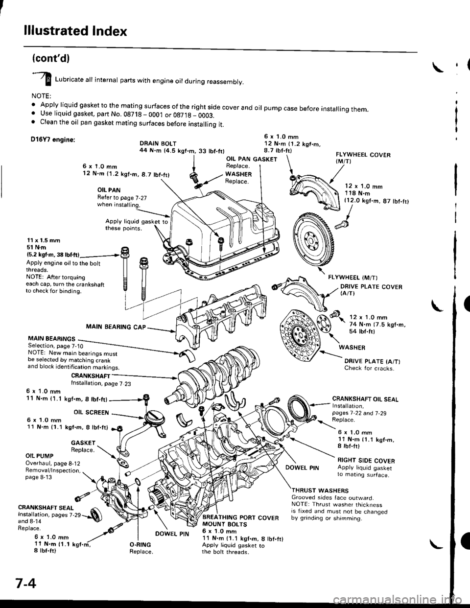
(cont'dl
I Luoricate att internal parts with engine oil during reassembly.
NOTE:
' Apply liquid gasket to the mating surfaces ofthe rightside coverand oil pumpcase before installingthem.. Use liquid gasket, part No. 08718 - 0001 or 087,18 _ OOO3.. Clean the oil pan gasket mating surfaces before installing it.
D16Y7 engine:6 x 1.0 mm12 N.m (1.2 kgt.m.8.7 tbf.tr)DRAIN BOLT44 N.m {4.5 kgt.m.33 tbt.ttl
,(
I
I
OIL PAN GASKETFLYWHEEL COVERIM/T)6x 1.0 mm12 N.m ('l .2 kgt.m, 8.7 tbt.trl
OIL PANRefer to page 7-27
Apply liquid gasker tothese points.
Replace.
WASHERReplace.12 x '1.0 mm118 N.m{12.0 kgt.m, 87 tbf.tr}
11 x 1.5 mm51 N.m15.2 kgl.m,38lbtftl
Apply engine oilto the boltthreads.NOTE: After torquingeach cap, turn the crankshaftto check for binding.
MAIN BEARINGSSelection, page 7-10
MAIN BEARING CAP
CRANKSHAFTInstallation, page 7 23
NOTE: New main bearings mustbe selected by matching crankand block identification markings.
6 r 1.0 mm11 N.m {1.1
6 x 1.0 mm11 N.m 11.1
ksI.m, 8 lbt.ft)
OIL SCREEN
kgt.m, 8 lbf.trl
Check for cracks.
CRANKSHAFT OIL SEALInstallation,pages 1 22 a^d 7-29
\:eprace'
GASKETReplace.
6 x 1.O mm11 N.m {1.1 kgt.m,8 rbt.frl
RIGHT SIDE COVERApply liquid gasker1o matrng surface,
OIL PUMPOverhaul, page 8-12Bemoval/lnspection,page 8-13
DOWEL PIN
WASHERSGrooved sides face outward.NOTE: Thrust washer thicknessis fixed and must not be changedby grinding or shimming.
CRANKSHAFT SEAL
l.j"Ji:l"^ pages z.2e --.S)
Replace.
6 x 1.0 mm11 N.m {1.18 tbt.fr)
7-4
BREATHING PORT COVERMOUNT BOLTS6 x 1.0 mm11 N.m {1.1 kgt.m, 8 tbf.fr}Apply liquid gasker tothe boh threads.
DOWEL PIN
Page 202 of 2189
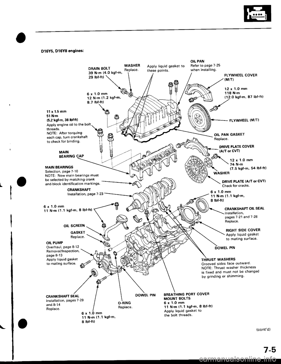
D16Y5, D16Y8 engines:
DRAIN BOLT39 N.m 14.0 kgt'm,
Apply liquid gasket to
these points.
OIL PANRefer to page 7-25
when installing.WASHERReplace.
29 lbl.tt)
\
\^
6 x 1.0 mm q%
P
I
FLYWHEEL COVER(M/T}
12 x 1.0 mm118 N.m(12.0 kgt.m, 87 lbt'ft)
FLYWHEEL (M/TI
t2 N.m 11.2 kgf'm,
8.7 lbl.ftl
11 x 1.5 mm
51 N.m(5.2 kgf'm, 38 lbf ftl
Apply engine oiltothe bolt
threads.NOTE: Aftertorquingeach cap, turn crankshaft
to check for binding.
MAINBEARING
MAIN BEARINGSSelection, page 7-10NOTE: New main bearings must
be selected by matching crank
"nJ lr."i io"irriti"",ion-markings. --------*-i6{\
CRANKSHAFTInstallation, page 7-23
6 r 1.0 mm11 N.m (1 1 kgf'm, I lbf'ttl
OII PAN GASKETReplace.
DRIVE PLATE COVER
{A/T or CVT)
12 r 1.0 mm
74 N.m
17.5 kgl.m, 54 lbf'ft)
DBIVE PLATE {A/T or CVTI
Check for cracks
6 x 1.O mm11 N.m {1.1 kgl'm,
8 tbl.ftl
CRANKSHAFT OIL SEAL
lnstallation,pages 7'?1 and '1 '28
Replace.
RIGHT SIDE COVER
Apply liquid gasket
to mating surface.
OIL SCREEN
GASKETReplace.
OIL PUMPOverhaul, page 8_12Removal/lnspection,page 8-13Apply liquid gasket
to mating surface.
DOWEL PIN
WASHEFS
Grooved sides tace outward
NOTE: Thrust washer thickness
is fixed and must not be changed
bV grinding or shimming.
CRANKSHAFT SEALInstallation, pages 7 29
and 8-14Replace.
BREATHING PORT COVER
MOUNT BOLTS6 x 1.O mm11 f{..n (1.1 kgf'm, 8 lbf'fl)
Apply liquid gasket to
the bolt threads.
O.RINGReplace.
6 x 1.0 mm
11 N.m (1 1 kgl'm,
8 tbr.ftl
(cont'd)
7-5
\
OOWEL PIN
Page 203 of 2189
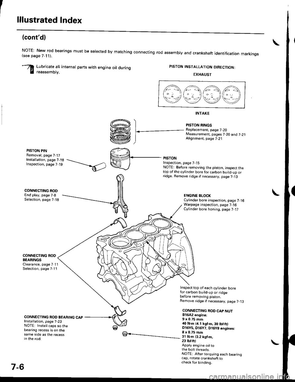
lllustrated Index
(cont'd)
NOTE: New rod bearings must be selected by matching connecting rod assembly and crankshaft(see page 7,11).identification markings
Lubricate all internal parts with engine oil duringreassembtv.
PISTON INSTALLATION DIRECTION:
EXHAUST
4\/=\6\z\
\e/!rqrf/
INTAKE
PISTON RINGSReplacement. page 7-20Measurement, pages 7 20 andj-21Alignment, page 7-21
PISTON PINRemoval, page 7,17Installation, page 7-18Inspection, page 7,19
CONNECTING RODEnd play, page 7-8Selection, page 7,18
CONNECTING RODBEARINGSClearance, page 7 11Selection, page 7-11
CONNECTING ROD BEARING CAPInstallation, page 7-23NOTE: lnstall caps so thebearing recess is on thesame side as the recessin the rod.
PISTONInspectron, page 7-15NOTE: Betore removing the piston, inspect thetop of the cylinder bore for carbon build-up orridge. Bemove ridge if necessary, page 7-13
ENGINE BLOCKCylinder bore inspection, page 7-16Warpage inspection, page 7,'16Cylinder bore honing, page 7,17
Inspect top of each cylinder borefor carbon build-up or ridgebefore removing piston.Remove ridge if necessary, page 7-13
CONNECTING ROD CAP NUT816A2 €ngin6:9 x 0.75 mm{0 N.m (4.1 kgt m, 30 tbf.ftlD16Y5, Dl6Y7. D16Y8 engines:8 x 0.75 mm3l N.m {3.2 kg{.m,23 tbt.fr)Apply engine oiltothe bolt threads.NOTE: After torquing each bearingcap, rotate crankshaft tocheck for binding.
7-6