check engine HONDA CIVIC 1998 6.G Repair Manual
[x] Cancel search | Manufacturer: HONDA, Model Year: 1998, Model line: CIVIC, Model: HONDA CIVIC 1998 6.GPages: 2189, PDF Size: 69.39 MB
Page 224 of 2189
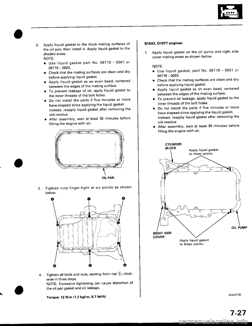
2. Apply liquid gasket to the block mating surfaces of
the oil pan, then install it. Apply liquid gasket to the
shaded areas.
NOTEI
. Use liquid gasket part No. 087 18 - 0001 or
08718 - 0003.
. Check that the mating surfaces are clean and dry
before apPlying liquid gasket.
. Apply liquid gasket as an even bead, centered
between the edges ol the mating surface'
. To prevent leakage of oil, apply liquid gasket to
the inner threads of the bolt holes
. Do not install the parts if five minutes or more
have elapsed since applying the liquid gasket
lnstead, reapply liquid gasket after removing the
old residue
. After assembly, wait at least 30 minutes before
filling the engine with oil.
Tighten nuts finger-tight
below.
OIL PAN
at six points as shown
I
3.
4. Tighten all bolts and nuts, starting from nut @, clock-
wise in three steps.
NOTE: Excessive tightening can cause distortion of
the oil pan gasket and oil leakage.
Torque: 12 N'm {1.2 kgt'm,8.7 lbf'ft|
816A2, D16Y7 engines:
1. Apply liquid gasket on the oil pump and right side
cover mating areas as shown below.
NOTE:
. Use liquid gasket, part No. 08718 - 0001 or
08718 - 0003.
. Check that the mating surfaces are clean and dry
before applying liquid gasket
. Apply liquid gasket as an even bead, centered
between the edges ol the mating surface'
. To prevent oil leakage, apply liquid gasket to the
inner threads of the bolt holes
. Do not install the parts if five minutes or more
have elapsed since applying the liquid gasket
Instead, reapply liquid gasket after removing the
old residue.
. Aftel assembly, wait at least 30 minutes before
filling the engine with oil.
CYLINDERELOCKApply liquid gasket
to these pornts-
Apply liquid gasket
to these pornts.
(cont'd)
7 -27
Page 226 of 2189
Oil Seals
lnstallation
NOTE:
. Engine removal is not required.
. The crankshaft oil seal housing should be dry.
Apply a light coat of grease to the crankshaft and to
the lips of the seals.
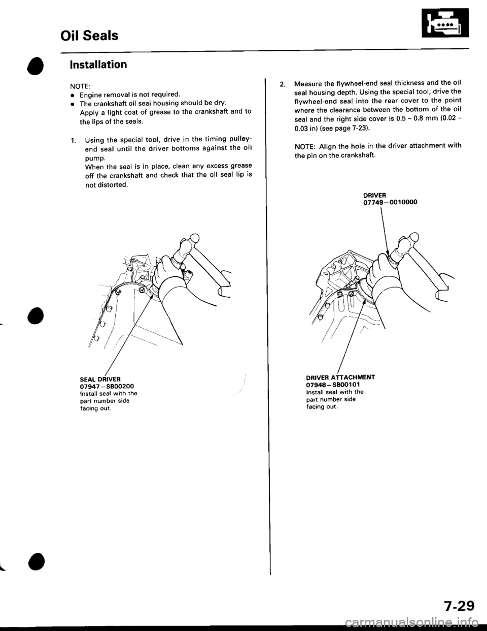
1. Using the special tool, drive in the timing pulley-
end seal until the driver bottoms against the oil
pump.
When the seal is in place, clean any excess grease
off the crankshaft and check that the oil seal lip is
not distorted.
07947 -S800200
lnstall seal with thepart number sadefacing out.
I
2. Measure the flvwheel-end seal thickness and the oil
seal housing depth. Using the special tool. drive the
flywheel-end seal into the rear cover to the point
where the clearance between the bottom of the oil
seal and the right side cover is 0.5 - 0.8 mm (0.02 -
0.03 in) (see page 7-23).
NOTE: Align the hole in the driver attachment with
the Din on the crankshaft.
DRIVER ATTACHMENT0794a-s800101lnslall seal with thepart number sidefacing out.
DRIVER07749-0010000
7 -29
Page 233 of 2189
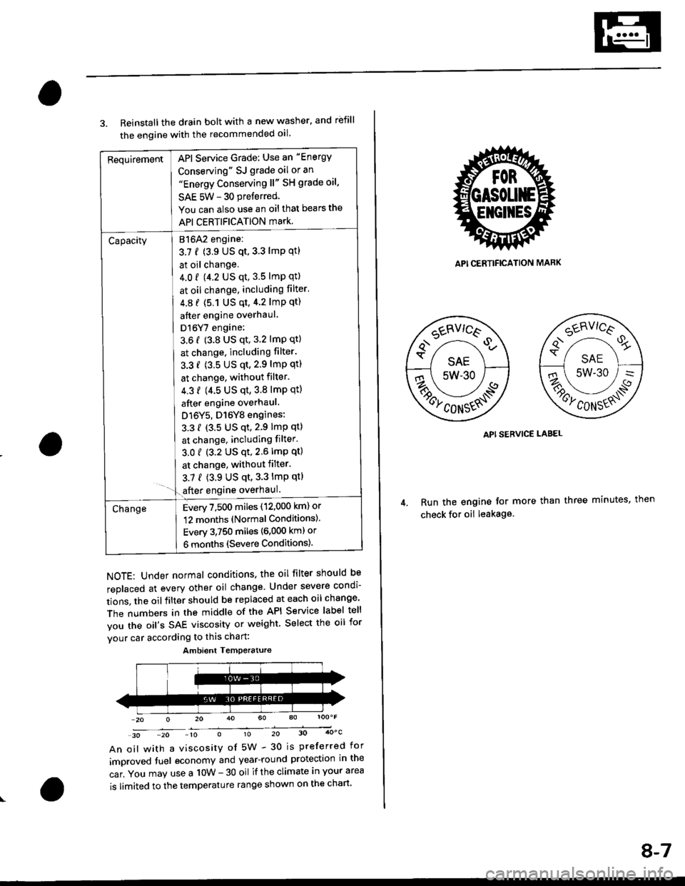
RequirementAPI Service Grade: Use an "Energy
Conserving" SJ grade oil or an"Energy Conserving ll" SH grade oil,
SAE 5W - 30 preferred
You can also use an oil that bears the
API CERTIFICATION mark.
Capacity[atolz engine:
3.7 f (3.9 US qt,3.3 lmp qtl
I at oil change.
J 4.0 r 9.2 US qt, 3.5 lmp qtl
I at oil change, including filter'
| 4.8 f (5.1 Us qt,4.2 lmp qt)
I after engine overhaul
I Dl6Y7 engine:
3.6 f (3.8 US qt, 3.2 lmP qt)
I at change. including filter.
I 3.3 f (3.5 US qt,2.9 lmP qtl
I at change, without filter.
I 4.3 f (4.5 us qt,3.8 lmp qtl
I after engine overhaul.
J D16Y5, D16Y8 engines:
L 3.3 { {3.5 US qt,2.9 lmp qt}
I at change, including filter.
3.01 (3.2 US qt,2.6lmp qt)
I at change, withoutfilter.
3.7 { (3.9 US qt,3.3 lmp qt}- '1.€fter engine overhaul.
ChangeEvery 7,500 miles (12,000 km) or
12 months (Normal Conditions).
Every 3,750 miles (6,000 kml or
6 months (Severe Conditions).
3. Reinstall the drain bolt with a new washer. and rbfill
the engine with the recommended oil.
NOTE: Under normal conditions, the oil filter should be
replaced at every other oil change Under severe condi-
tions, the oilfilter should be replaced at each oil change'
The numbers in the middle of the API Service label tell
you the oil's SAE viscosity or weight Select the oil for
vour car according to this chart:
30 20 -10 010 20 30 4OoC
An oil with a viscosity of 5W - 30 is preferred for
improved tuel economy and year-round protection in the
car. You may use a 10W - 30 oil if the climate in your area
is limited to the temperature range shown on the chart'
Ambient Temoerature
API CERTIFICATION MARK
API SERVICE LABEL
Run the engine tor more than three minutes, then
check for oii leakage
8-7
Page 235 of 2189
Oil Pressure
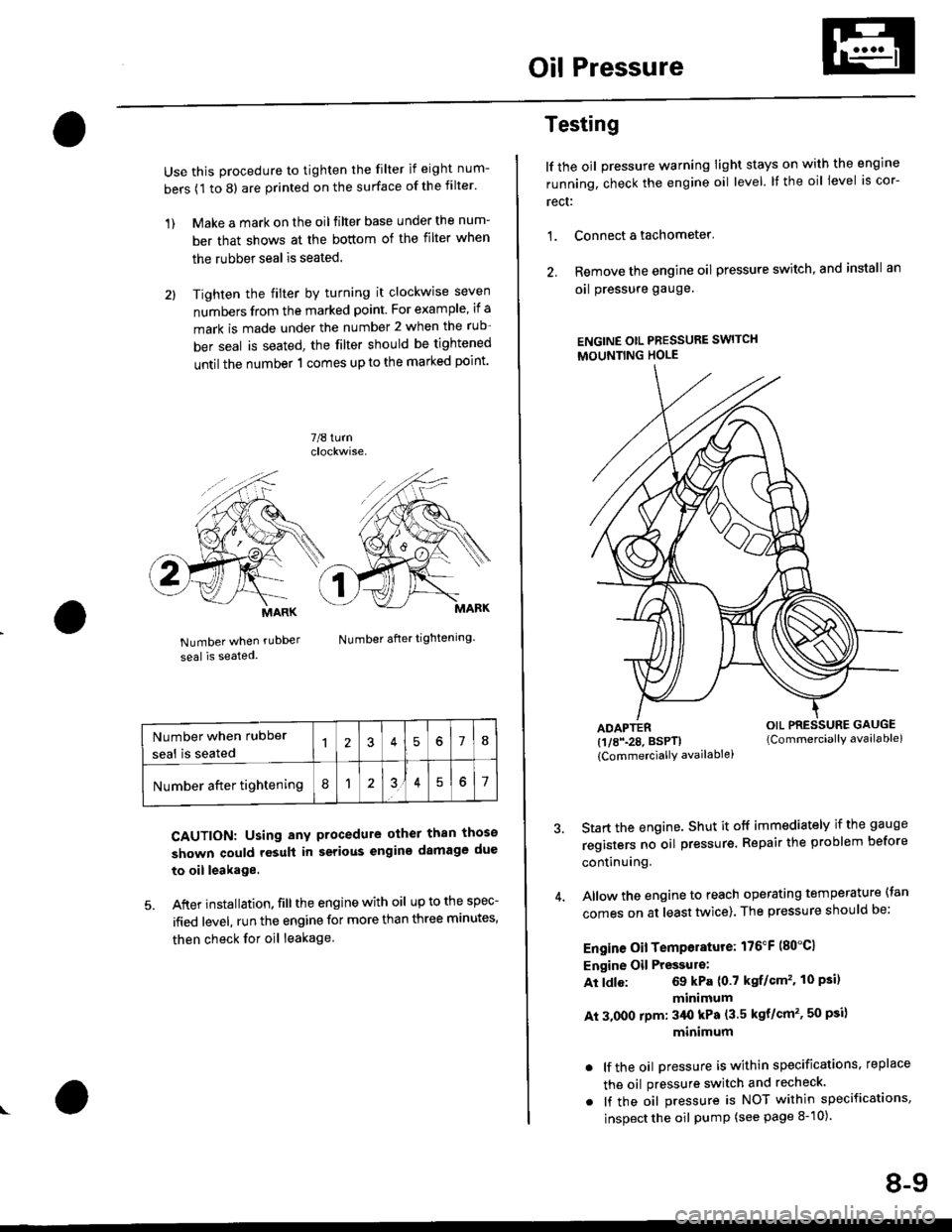
Use this procedure to tighten the filter if eight num-
bers (1 to 8) are printed on the surface of the filter.
1) Make a mark on the oil filter base under the num-
ber that shows at the bottom of the filter when
the rubber seal is seated.
2l Tighten the filter by turning it clockwise seven
numbers from the marked point. For example, if a
mark is made under the number 2 when the rub
ber seal is seated, the filter should be tightened
until the number 1 comes up to the marked point'
7/8 turn
Number when rubDer
seal is seated
Number after tightening.
CAUTION: Using any procedure other than those
shown could rosult in serious engins damage due
to oil leakage
5. After installation. fill the engine with oil up to the spec-
ified level, run the engine for more than three minutes,
then check for oil leakage
MARK
Number when rubber
seal is seated578
Number after tightening8151
Testing
lf the oil pressure warning Iight stays on with the engine
running, check the engine oil level. It the oil level is cor-
rect:
1. Connect a tachometer'
2. Remove the engine oil pressure switch, and install an
oal pressure gauge.
ENGINE OtL PRESSURE SWITCH
MOUNTING HOLE
ADAPTER(1/8\28. BSPTI
{CommerciallY availablei
Start the engine. Shut it off immediately if the gauge
registers no oil pr€ssure. Repair the problem before
continuing.
Allow the engine to reach operating temperature (tan
comes on at least tlivice). The pressure should be;
Engine Oil Temperature: 176"F (80"C1
Engine Oil Pressulo:
At ldle: 69 kPa (0.7 kgf/Gm'�. 10 Psi)
minimum
At 3.000 rpm: 3/Ut kPa (3.5 kgt/cm'�, 50 psi)
minimum
. lf the oil Dressure is within specifications, replace
the oil pressure switch and recheck.
. lf the oil pressure is NOT within specifications,
inspect the oil pump (see page 8-10).
OIL PRESSURE GAUGE(Commerciallv available)
8-9
Page 236 of 2189
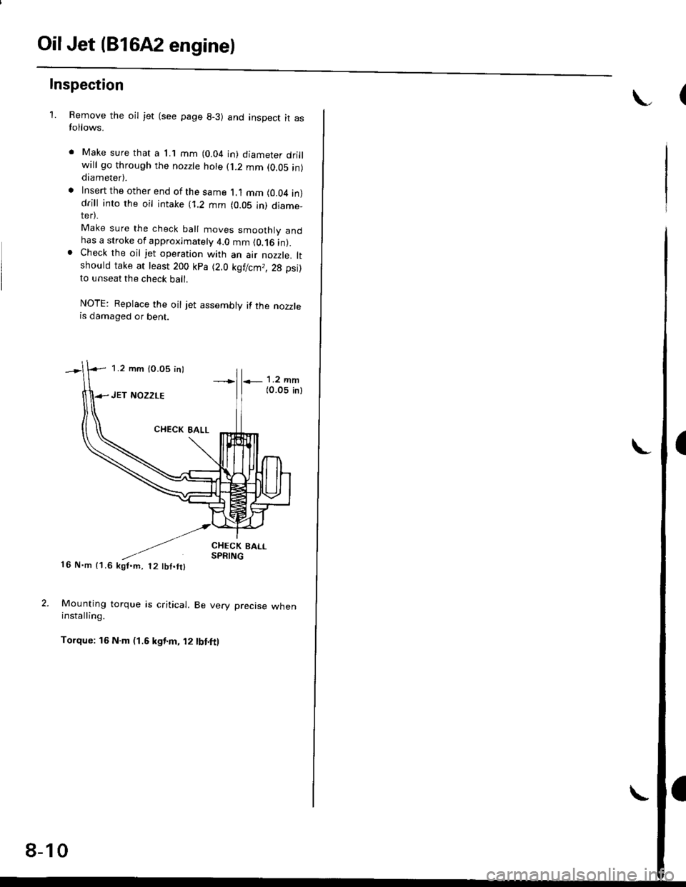
OilJet (B1642 engine)
Inspection
1.Remove the oil jet (see page 8-3) and inspect it asfollows.
Make sure that a 1.1 mm (0.04 in) diameter drillwill go through the nozzte hole (j.2 mm (0.05 in)diameter).
Insert the other end of the same 1.1 mm (0.04 in)drill into rhe oil intake (i.2 mm (0.05 in) diame_ter).
Make sure the check ball moves smoothly andhas a stroke of approximately 4.0 mm (0.16 in).Check the oil jet operation with an air nozzle. ltshould take at least 200 kPa (2.0 kgf/cm,, 28 psi)to unseat the check ball.
NOTE: Replace the oil jet assembly if the nozzlers damaged or bent.
CHECK BALLSPRING16 N.m 11.6 kgf,m, t2 tbf.fil
Mounting torque is critical. Be very precise wheninstalling.
Torque: 16 N.m (1.6 kgt.m, 12 tbt.ft)
1.2 mm (0.05 inl
8-10
Page 237 of 2189
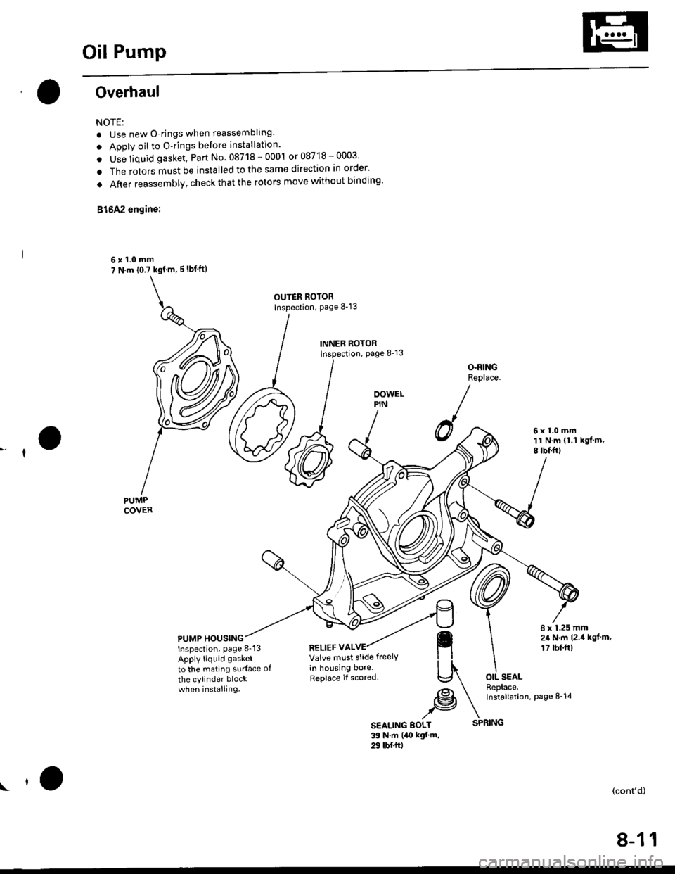
Oil Pump
Overhaul
NOTE:
. Use new O rings when reassembllng.
. Apply oil to O-rings before installation.
. Use liquid gasket, Part No. 08718 - 0001 or 08718 - 0003
. The rotors must be installed to the same direction in order'
o After reassembly, check that the rolors move without binding'
B15A2 engine:
6x1.0mm7 N.m (0.7 kgf m, 5 lbf ft)
OUTER ROTORInspection, page 8-13
INNER ROTORpage 8-13
OOWELPIN
O-RINGReplace.
6x1.0mm11 N.m (1.1
8 tbtfrlkgf.m,
PUMP HOUSINGInspection, page 8-13
Apply liquid gasket
to the mating surface of
the cylinder blockwhen installing.
8 x 1.25 mm24 N,m {2.i1 kgl.m.
17 tbf.ft)RELIEF VALVEValve mlst slide freeiy
in housing bore.Replace if scored.OIL SEALReplace.lnstallation,page 8-14
SEALING BOLT39 N.m l4O kgt'm,29 tbt frl
\(cont'd)
SPRING
8-11
Page 238 of 2189
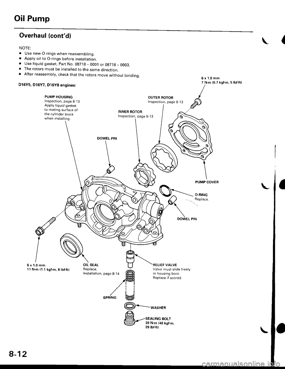
Oil Pump
Overhaul (cont'dl
NOIE:
. Use new O rings when reassembling.. Apply oil to O rings before instalraUon.. Use liquid gasket, Parr No. 08718 - 0001 or08718_0003.. The rotors must be installed to the same direction.. After reassembly, check that the rotors move without binding.
D16Y5, D16Y7, D16Y8 engines:
(
6x1.0mm7 N.m (0.7 kgI.m, 5 lbf ftl
PUMP HOUSINGInspection, page 8 13Apply liquid gasketto mating surface ofthe cylinder biockwhen installing.
INNER ROTORInspectron, page 8 13
DOWEL PIN
PUMP COVEB
O-RING
_.feor,""
\6x1.0mm11 N.m {1.1 kgf.m,8lbl.ft)RELIEF VALVEValve must slide freelyin housing bore.Replace if scored
OIL SEAL
[".?li;:;"". *,", ,.rg
""rc
@.-*or"."
9''ggttt*
8-12
Page 239 of 2189
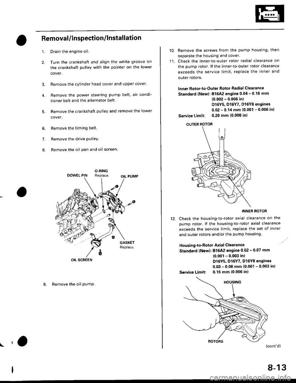
4.
Removal/lnspection/lnstallation
2.
3.
1.
5.
6.
1.
8.
Drain the engine oil.
Turn the crankshaft and align the white groove on
the crankshaft pulley with the pointer on the lower
cover.
Remove the cylinder head cover and upper cover'
Remove the power steering pump belt, air condi-
tioner beit and the alternator belt
Remove the crankshaft pulley and remove the lower
cover.
Remove the timing belt.
Remove the drive pulley.
Remove the oil pan and oil screen.
O.RINGReplaceOOWEL PIN
OIL SCREEN
9. Remove the oil PumP.
!'a
10.Remove the screws from the pump housing, then
separate the housing and cover'
Check the inner-to-outer rotor radial clearance on
the pump rotor. lf the inner-to outer rotor clearance
exceeds the service limit, replace the inner and
outer rotors.
lnner Rotor-to-Outer Rotor Radial Clearance
Standard {New}: 815A2 engine 0.04 - 0.16 mm
(0 002 - 0'006 in)
D16Y5, D16Y7, D16Y8 engines
0.02 - 0.14 mm 10.001 - 0.006 in)
Service Limit: 0.20 mm (0 008 inl
OUTER ROTOR
INNER ROTOR
Check the housing-to-rotor axial clearance on the
pump rotor. lf the housing-to rotor axial clearance
exceeds the service limit, replace the set of inner
and outer rotors and/or the pump housing
Housing-to-Rotor Axial Clearance
Standard (N€w): 816A2 engine 0.02 - 0.07 mm
(0.001 - 0.003 inl
D16Y5, D16Y7, D16Y8 engines
0.03 - 0.08 mm (0.001 - 0.003 inl
S€rvice Limit: 0.15 mm 10.006 in)
11.
't2.
(cont'd)
8-13
Page 240 of 2189
Oil Pump
RemovaUlnspection/lnstallation (cont'dl
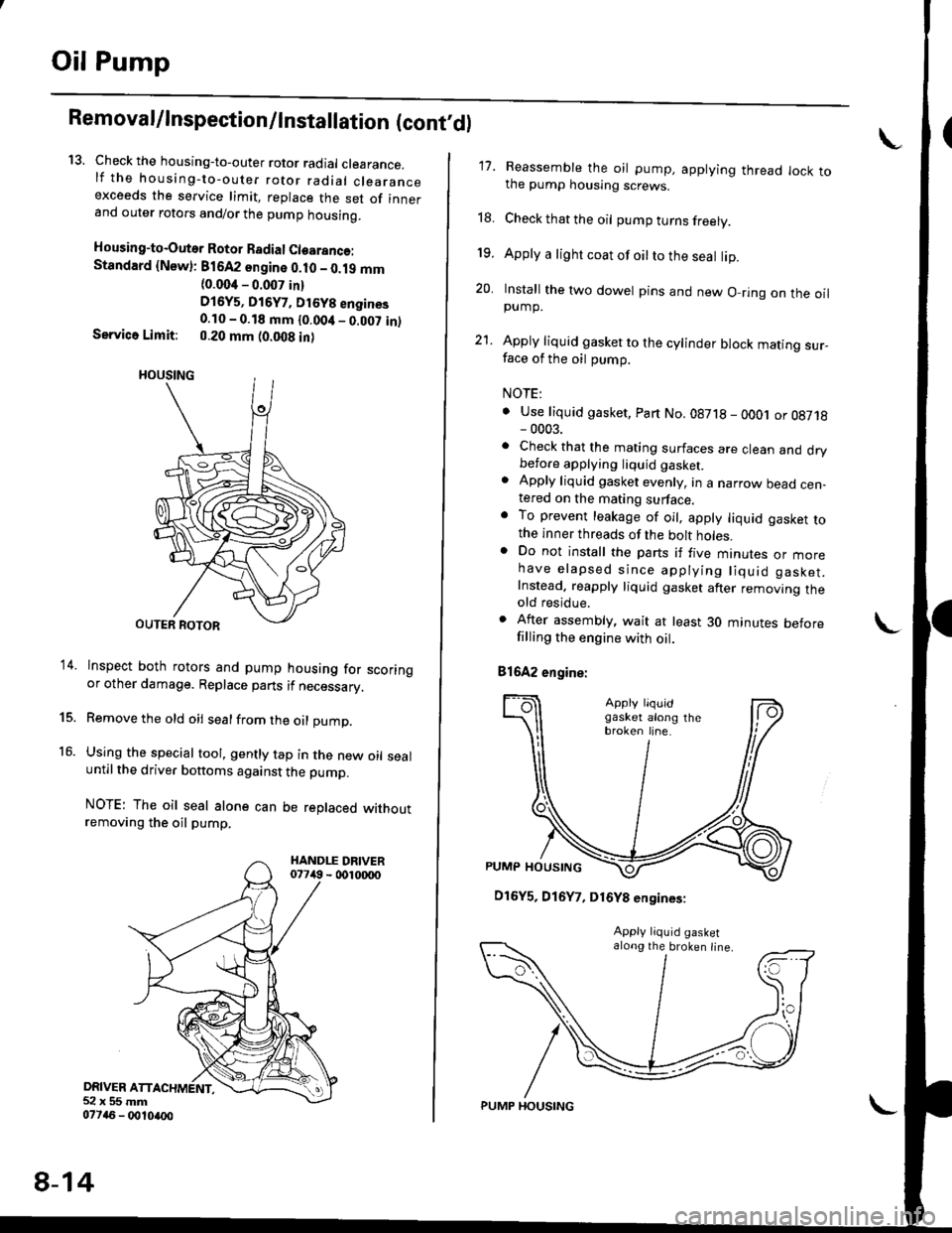
13. Check the housing-to-outer rotor radial clearance.lf the housing-to-outer rotor radial clearanceexceeds the service limit, replace the set of innerand outer rotors and/or the pump housing.
Housing-to-Outer Rotor Badial Clearanco:Standard {Newl: 816A2 sngine 0.10 - 0.19 mm(0.004 - 0.007 in)
D16y5, Di6y7, Dt6y8 engines0.10 - 0.18 mm {0.00it _ 0.007 in)Service Limit: 0.20 mm (0.008 in)
lnspect both rotors and pump housing for scoringor other damage. Replace parts if necessary.
Remove the old oil sealfrom the oil pump.
Using the special tool, gently tap in the new oil sealuntil the driver bottoms against the pump.
NOTE: The oil seal alone can be replaced withoutremoving the oil pump.
DRIVER ATT52x55mm077a6 - 0010ao0
14.
15.
16.
8-14
PUMP HOUSING
17. Reassemble the oil pump, applying thread lock tothe pump housing screws.
18. Check that the oil pump turns freely.
19. Apply a light coat of oilto the seal lip.
20. Install the two dowel pins and new O-ring on the oilpump.
21. Apply liquid gasket to the cylinder block mating sur_face of the oil pump.
NOTE:
. Use liquid gasket, Part No.08718 - oOOj or 08718- 0003.. Check that the mating surfaces are clean and drybefore applying liquid gaskel. Apply liquid gasket evenly, in a narrow bead cen-tered on the mating surface.o To prevent leakage of oil, apply liquid gasket tothe inner threads of the bolt holes.. Do not install the parts if five mtnures or morehave elapsed since applying liquid gasket.Instead. reapply liquid gasket after removing theold residue.
. After assembly, wait at least 30 minutes beforefilling the engine with oil.
81642 engine:
\
D16Y5, D16Y7, D16Y8 engines:
along the broken line.
Page 241 of 2189
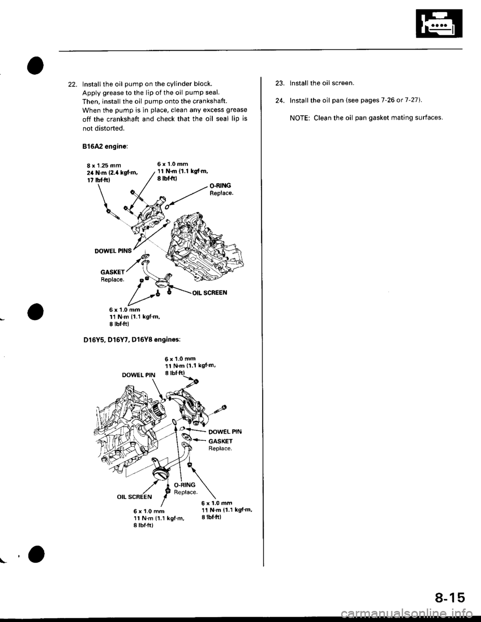
22. Installthe oil pump on the cylinder block.
Apply grease to the lip ot the oil pump seal.
Then. install the oil pump onto the crankshaft.
When the pump is in place, clean any excess grease
off the crankshaft and check that the oil seal lip is
not distorted.
81642 engine:
8 x 1.25 mm6x1.Omm
24 N.m (2.i4 kg[.m,17 tbl.trl
11 N.m {1.1 kg{.m,8 rbt ft)O.RI GReplace.
DOWEL PINS
GASKETReplace.
OIL SCREEN
6x1.0mmrl N.m {1.1 kgf'm,I tbf.ftl
D16Y5, D16Y7. D16Y8 enginos:
OOWEL PIN
6x1.0mm11N'm (1.1 kgf m'
O.RINGReplace.
DOW€L PIN
GASKETReplace.
6x1.0mm
6 x 1.0 mm '11 N'm {1 1 kgf'm,
11 N.m (1.1 kgf.m, I lbf ftl
8 lbf.ft)
!o
8-15
lnstall the oil screen.
Install the oil pan (see pages 7-26 or 7-27).
NOTE: Clean the oil pan gasket mating surfaces.