idle control system HONDA CIVIC 1998 6.G Workshop Manual
[x] Cancel search | Manufacturer: HONDA, Model Year: 1998, Model line: CIVIC, Model: HONDA CIVIC 1998 6.GPages: 2189, PDF Size: 69.39 MB
Page 39 of 2189
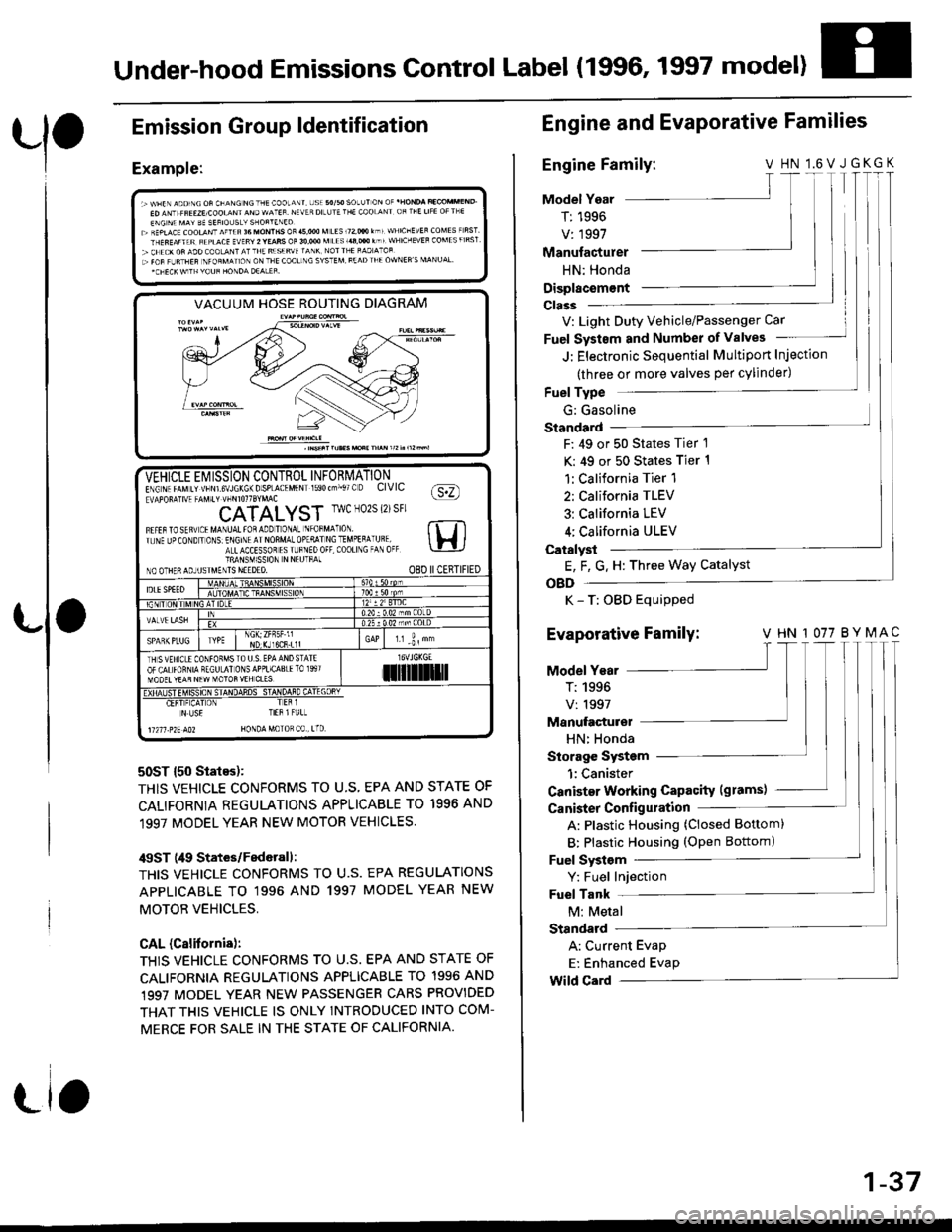
Under-hood Emissions Control Label (1996, 1997 model)
Emission
Example:
Group ldentification
VACUUM HOSE ROUTING DIAGRAM
50ST {50 States):
THIS VEHICLE CONFORMS TO U.S, EPA AND STATE OF
CALIFORNIA REGULATIONS APPLICABLE TO 1996 AND
1997 MODEL YEAR NEW MOTOR VEHICLES.
/$ST (49 States/Federall:
THIS VEHICLE CONFORMS TO U.S. EPA REGULATIONS
APPLICABLE TO '1996 AND 1997 MODEL YEAR NEW
MOTOB VEHICLES,
CAL (Calitornis):
THIS VEHICLE CONFORMS TO U.S. EPA AND STATE OF
CALIFORNIA REGULATIONS APPLICABLE TO 1996 AND,1997 MODEL YEAR NEW PASSENGER CARS PROVIDED
THAT THIS VEHICLE IS ONLY INTROOUCED INTO COM-
MERCE FOR SALE IN THE STATE OF CALIFORNIA.
-VEHICLE Ei/ ISSION CONTROL INFORMATIONE\G\. rrMrr vtsNrs\JLK6\Dsp-A(.MFN 590(--,. O CIVIC fa:n!APOF!]V4 -AV.t' !-rirorrSrMAc \Y:/
CATALYST IwcN02S{2)sFr
Fl.tarostq! tMA\uAttoaaooTo\a- \'oFM^ ro rt Tlr. \F Jo(O\D ' O\S E\Gr\l AINOnMA-OolqllNCTMoEqA Uql lH ia-LACCESSoT rS r-F\Eo0F C00ll\G -A 0( \-!-lJTRANSM1SSION N NEUTFAINO OTHERAOJUSIMENTS NEEDEO. O8D IICERTIFIED
IDLESPEEOATDC
NDr(Jl6CR.L1lr.r -i, "
TH SVEH CLE CONfOFMSTO U S. EPA AND STATEOF CALfORNIA RECULAI ONSAPPLICA8IElO 1997MOOET YEAR NEW MOTOR VEH CL'Silil]]lrl
Er!4#_"E!!ifl 4q!sq+HT-q4E!rL
N US€ TIEB l FULL
11211 .?2E AO2 HONDA MoTOR C0 , tTD
Engine and EvaPorative Families
Engine Family:V HN l.6VJGKGK
Model Year
T: 1996
V: 1997
T I
T|I
Manufacturer
HN: Honda
Displacem€nt
V: Light Duty Vehicle/Passenger Car
Fuel Systsm and Number of valves
J: Electronic Sequential Multiport Injection
(three or more valves per cylinder)
Fuel Type
G: Gasoline
Standard
F: 49 or 50 States Tier 1
K: 49 or 50 States Tier 1
1:California Tier 1
2: California TLEV
3: California LEV
4; California ULEV
Catalyst
E, F, G. H: Three Way Catalyst
OBD
K - T: OBD Equipped
Evaporative Family: v HN 1077 BYMAc'|T
Model Year
T:1996 |V:1997 lManufacturel
HN: Honda
Storage System
1:Canister
Canister Working Capacity (grams)
Canister Configulation
A: Plastic Housing (Closed Bottom)
B: Plastic Housing (oPen Bottom)
Fuel Systsm
Y: Fuel Injection
Fuel Tank
M: Metal
Standard
A: Current Evap
E: Enhanced Evap
Wild Card
1-37
Page 289 of 2189
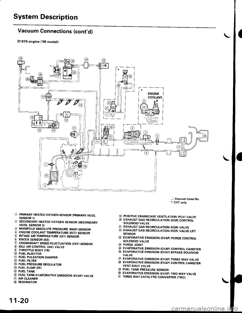
System Description
Vacuum Connections (cont'd)
D16Y5 engine ('98 modet):
-: Vacuum hose No,*: CW only
(9 POSITIVE CRANKCASE VENTILATION {PCV} VALVE?!J EXHAUST GAS BECIRCULATION (EGR}CONTROLSOLENOIO VALVE'1 ExHAUST GAs RECIRCULATIoN IEGRI VALVE22 EXHAUST GAS RECIRCULATION {EGR} VALVE LIFISENSOR€J EvApoRATtvE EMtsstoN {EvAp} puRGE coNTRoLSOLENOID VALVEq4 PURGE JOINT@ EVAPoRATIVE EMIssIoN {EVAP) coNTRoL CANISTER@� EVAPORATIVE EMISSION IEVAP} BYPASS SOLENOIDVALVE?? EVAPORATIVE EMISSION {EVAP) THREE WAY VALVEITII EVAPORATIVE EMISSION IEVAP} CONTROL CANISTERVENT SHUT VALVEO FUEL TANK PRESSURE sENsoRQlI EVAPORATIVE EMISSION {EVAP}TWO WAY VALVE8' THREE WAY CATALYTIC CONVERTER {TWCI
il) PRIMAFY HEATED OXYGEN SENSOR IPRIMARY HO2S.SENSOR 1)O SECoNDARY HEATEo oxYGEN sENsoR {sEcoNDARYHO2S. SENSOB 2)iq] MANIFOLD ABSOLUTE PRESSURE (MAPI SENSORO ENGINE COOLANT TEMPERATURE IECT) SENSOR5 INTAKE AIR TEMPERATURE {IATI SENSOR! KNOCK SENSOR tKSlO CRANKSHAFT SPEED FLUCTUATIoN {cKF) sENsoFO IDLE AIR coNTRoL {IAc) vALvE99 THROTTLE BODY ITBI@ FUEL INJECToRO FUEL PULSATION DAMPER@ FUEL F -TER@ FUEL PRESSURE REGULAToR[4 FUEL PUMP IFPI(9 FUEL TANK(D FUEL TANK EVAPoRATIVE EMIssIoN IEVAPI VALVEO' AIR CLEANER(D RESoNAToR
11-20
Page 291 of 2189
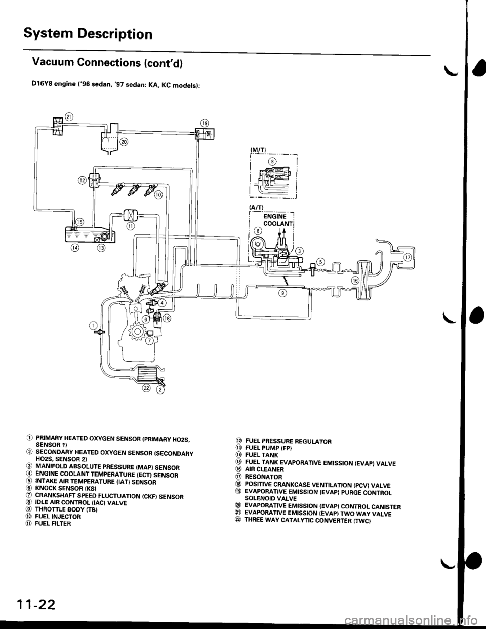
System Description
Vacuum Connections (cont'd)
D16Y8 engine ('96 sedan, '97 sedan: KA, KC modelsl:
PRIMARY HEATED OXYGEN SENSOR (PRIMARY HO2S.SENSOR SECONOARY HEATED OXYGEN SENSOR {SECONDARYHO2S, SENSOR 2lMANIFOLD ABSOLUTE PRESSUBE {MAPI SENSORENGINE COOLANT TEMPERATURE {ECTI SENSORINTAKE AIR TEMPERATUFE IIATI SENSORKNOCK SENSOR IKSICRANKSHAFT SPEED FLUCTUATION {CKFI SENSORIDLE AIR CONTROL IIACI VALVETHROTTLE EODY (T8)FUEL INJECTORFUEL FILTER
FUEL PRESSURE REGULATORFUEL PUMP {FPIFUEL TANKFUEL TANK EVAPORATIVE EMISSION IEVAP} VALVEAIR CLEANERRESONATORPOSITIVE CRANKCASE VENTILATION {PCV} VALVEEVAPORATIVE EMISSION IEVAP) PURGE CONTROLSOLENOID VALVEEVAPORATIVE EMISSION IEVAPI CONTROL CANISTEREVAFORATIVE EMISSION IEVAP} TWO WAY VALVETHREE WAY CATALYTIC CONVERTER (TWC'
{M/T}
i@l: F@i
HiiFl
(A/T)
I ENGINE I
I coor-rruri
i@ i+ il/A. nfi |(Or)l /U[ |)l#t,/,6
0)
t;
-l
@
!o,(t
@@@
@@@(9
@@@(D
@A)@
11-22
Page 293 of 2189
![HONDA CIVIC 1998 6.G Workshop Manual System Description
Vacuum Connections (contdl
D16Y8 engine l99 - 00 modetsl:
(]-i PAIMARY HEATEO OXYGEN SENSOR {PRIMARY HO2S,SENSOR 1)..2r SECONOARY HEATEO OXycEN SENSOB ISECONDARYHO2S, SENSOR 2li3) HONDA CIVIC 1998 6.G Workshop Manual System Description
Vacuum Connections (contdl
D16Y8 engine l99 - 00 modetsl:
(]-i PAIMARY HEATEO OXYGEN SENSOR {PRIMARY HO2S,SENSOR 1)..2r SECONOARY HEATEO OXycEN SENSOB ISECONDARYHO2S, SENSOR 2li3)](/img/13/6068/w960_6068-292.png)
System Description
Vacuum Connections (cont'dl
D16Y8 engine l'99 - 00 modetsl:
(]-i PAIMARY HEATEO OXYGEN SENSOR {PRIMARY HO2S,SENSOR 1)..2r SECONOARY HEATEO OXycEN SENSOB ISECONDARYHO2S, SENSOR 2li3) MANIFOLD ABSOLUTE PBESSURE {MAPI SENSORO ENGINE cooLANT TEMPERATURE (ECTI sENsoR(5) INTAKE AIR TEMPERATURE {IAT} sENsoRG] KNOCK SENSOR IKSI?r CRANKSHAFT SPEEo FLUCTUATTON {CKF) SENSOR.O IDLE AIR coNTRoL {IAc)vALvEi-9] THROTTLE BOOY {TB)(O FUEL INJECToRI]'i FUEL FILTER.O FUEL PRESSURE REGULAToR[t FUEL PUMP {FPl.D FUEL TANKil' AIR CLEANERTD RESONATORO FUEL TNJEC oN AtR tFtA) coNTRoL vAt_vE.19 POSITIVE CRANKCASE VENTILATION {PCVI VALVE
.19) EVAPORATIVE EMIssIoN {EVAP) PURGE coNTBoLSOLENOID VALVE€g PURGE JorNTtj EVApoRATtvE EMtsstoN {Evap} coNTRoL cANtsTERC4 EVAPONANVE EMISSION (EVAP) BYPASS SOLENOIDVALVE
?3 EVAPORATIVE EMISSION {EVAP} CONTROL CANISTERFILTERA4 EVAPoBATIVE EMIssIoN (EVAP) coNTRoL CANISTERVENT SHUT VALVEC! FUEL TANK PRESSURE sENsoREO EVAPOBATIVE EMISSION (EVAP) TWO WAY VALVEe? oNBoARD REFUELtiIG vApoR REcovERy {oRvR} VENTSHUT VALVE@ oNBoARD REFUELTNG vapoR REcovERy (oRvR) vapoRRECIRCULATION VALVEiP THREE WAY CATAI.YTIC CONVEBTER {TWCI
'- *o'*- -
COOLANT
]L
nrl
L
ii8'x'", *
--j IIM TTI ^n 14 [l(2i)-fr l-1ry|
11-24
Page 297 of 2189
I
a
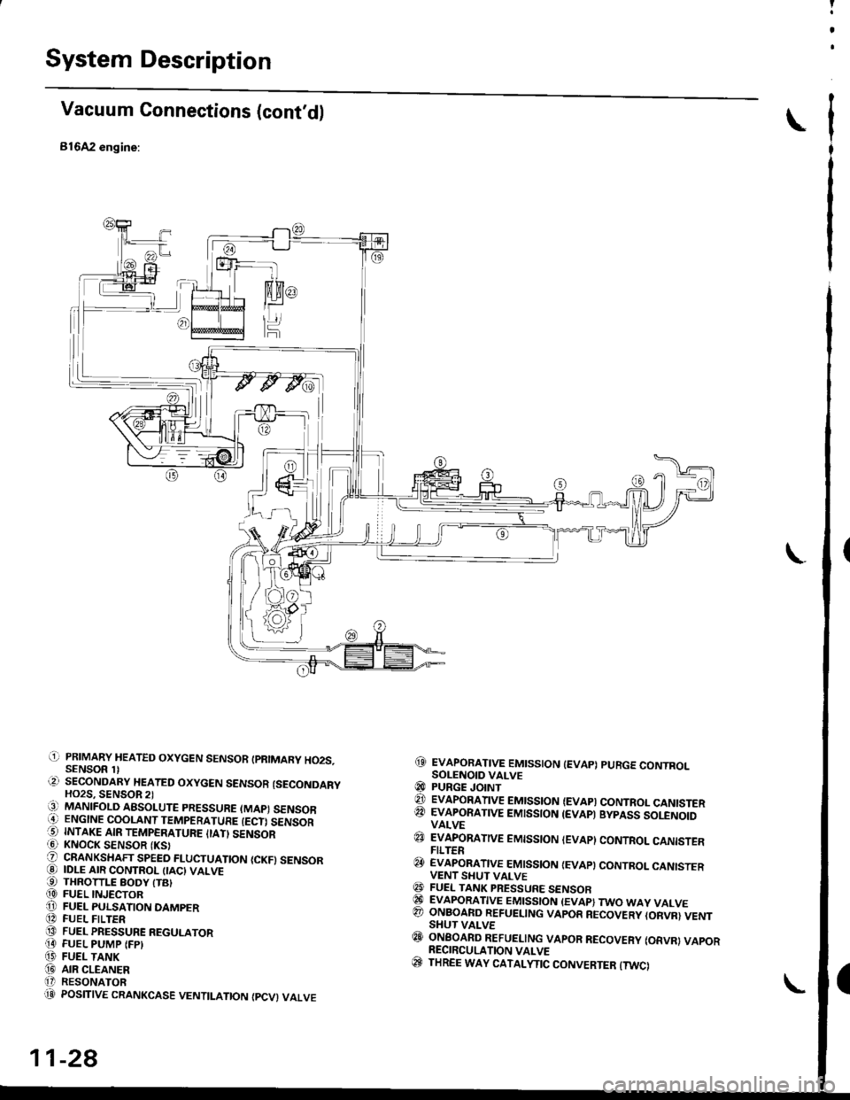
System Description
Vacuum Connections (cont'd)
816A2 engine:
@ EvApoRATtvE EMtsstoN tEvAp) puRGE coNTRoLSOLENOID VALVE@ PURGE JoINT€t EvApoRATtvE EMtsstoN (EVApt coNTRoL caNtsTERQA EVAPORATIVE EMISSION (EVAP) BYPASS SOLENOIDVALVE
@ EVApoRATtvE EMtsstoN lEvApl coNTRoL caNtsrERFILTER@ EvApoRATtvE EMtsstoN {EvApt coNrRoL cANtsrERVENT SHUT VALVE@ FUEL TANK PRESSURE sENsoRGI EVAPORATIVE EMISSION (EVAP} TWO WAY VALVE@ ONBOARD REFUETING VAPOR RECOVERY {ORVR} VENTSHUT VALVE@ oNBoAnD REFUELING vApoR REcovERy (oRvRl vApoR. RECIRCULATION VALVE(c} THREE WAY CATALYTIC CONVERTER {TWCI
(' PRIMARY HEATED OXYGEN SENSOR IPRIMARY HO2S.SENSOR 1l.?) SECONDARY HEATED OXYGEN SENSOR {SECONDARYHO2S, SENSOR 2)13] MANIFOLD ABSoLUTE PRESSURE (MAP) sENsoBi' ENGINE COOLANT TEMPERATURE IECT) SENSORO INTAKE AIR TEMPERATURE ITATI SENSORi6l KNOCK SENSOR {KS}O oRANKSHAFT SPEED FLUCTUATIoN {cKF} sENsoR@ IDLE AIR coNTRoL (IAc} VALVE€) THRoTTLE BoDy trB|(D FUEL INJECToRO FUEL PULSATIoN DAMPER[D FUEL FILTER@ FUEL PRESSURE REGULAToR!I FUEL PUMP IFP)f,' FUEL TANK(iD ArR CLEANERt' RESONAToR'.1]i POSITIVE cRANKcAsE VENTILATIoN {Pcv} VALVE
11-28
Page 373 of 2189
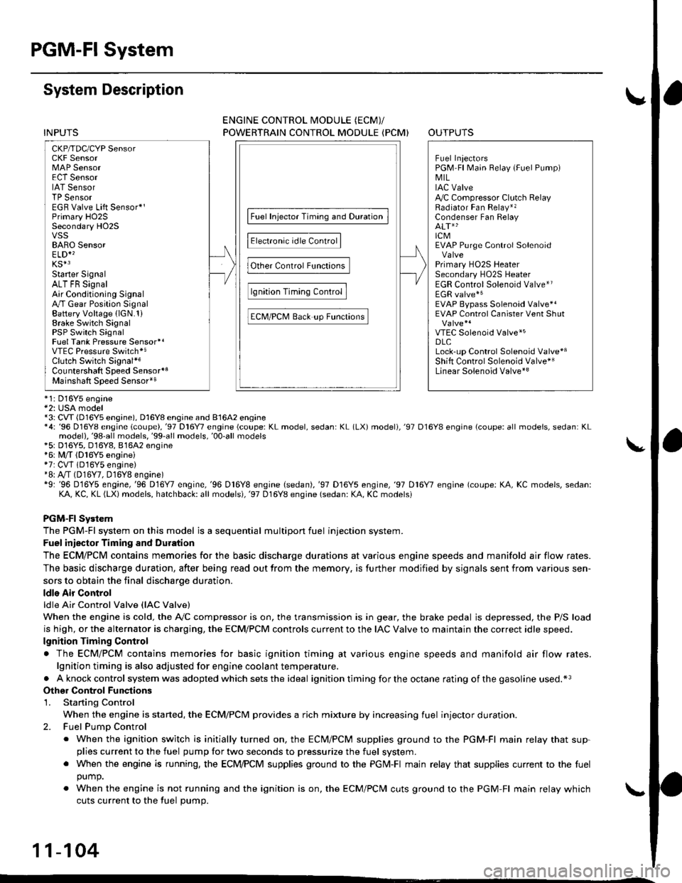
PGM-FI System
System Description
CKP/TDC/CYP Sensor
MAP Sensor
IAT SensorTP SensorEGR Valve Lift Sensor*'Primary H02SSecondary HO2SVSSBARO SensorELD*'KS€Starter SignalALT FR SignalAir Conditioning SignalA/T Gear Position SignalBattery Voltage {lGN.1}Erake Switch SignalPSP Switch SignalFuel Tank Pressure Sensor*iVTEC Pressure Switch*5Clutch Switch Signal*6Countershaft Speed SensornBMainshaft Speed Sensorrs
-\
----t /
F;ilrr j"-----fi-tri-'r.;l
Fb"t."'i" d" c;;il
F,h"'c;;tr*".io";-l
@."r.l"sc;;ll
EaM/PcM B""k-p F"""till
r\
-:/
Fuel IniectorsPGM-Fl Main Belay {Fuel Pump)MILIAC Valve!y'C Compressor Clutch RelayRadiator Fan Relay*,Condenser Fan RelayALT*'lcMEVAP Purge Control Solenoid
Primary HO2S HeaterSecondary H02S HeaterEGR Control Solenoid Valve*rEGR valve*6EVAP Bypass Solenoid Valve*'EVAP Control Canister Vent Shut
VTEC Solenoid Valve*5DLCLock-up Control Solenoid Valve*aShift Control Solenoid Valve*3Linear Solenoid Valve*3
*1: Dl6Y5 engine*2: USA model*3: CW (D16Y5 ensine), D16Y8 engine and 81642 ensine*4: '96 D16Y8 engine lcoupe),'97 Dl6Y7 engine (coupe: KL model, sedan: KL (LX) model),'97 D16Y8 engine {coupe: all models, sedan: KLmodel),'98-all models,'99'all models,'00-all models+5: D16Y5, D16Y8,816A2 engine*6: M/T (D16Y5 enginei*7: CVT 1D'l6Y5 engine)+8: A/T (D16Y7, D16Y8 engine)*9: '96 D16Y5 engine,'96 D16Y7 engine,'96 Dl6Y8 engine (sedan),'97 D16Y5 engine,'97 Dl6Y7 engine (coupe: KA, KC models, sedan:KA, KC, KL (LX) models, hatchback: all models),'97 D16Y8 engine (sedan: KA, KC modelsi
PGM-FI Sy3lem
The PGM-Fl system on this model is a sequential multipon fuel injection system.
Fuel iniector Timing and Duration
The ECM/PCM contains memories for the basic discharge durations at various engine speeds and manifold air flow rates.
The basic discharge duration, after being read out from the memory. is further modified by signals sent from various sen-
sors to obtain the final discharge duration.
ldle Air Control
ldle Air Control Valve llAC Valve)
When the engine is cold. the A,/C compressor is on, the transmission is in gear, the brake pedal is depressed, the P/S load
is high, or the alternator is charging, the ECM/PCM controls current to the IAC Valve to maintain the correct idle speed.
lgnition Timing Control
. The ECM/PCM contains memories for basic ignition timing at various engine speeds and manifold air flow rates.
lgnition timing is also adjusted for engine coolant temperature.
. Aknockcontrol system was adopted which sets the ideal ignition timing for the octane rating ofthegasoline used.*3
Othgr Control Funqtions
1. Starting Control
When the engine is started, the ECM/PCM provides a rich mixture by increasing fuel injector duration.
2. Fuel Pump Control
. When the ignition switch is initially turned on, the ECM/PCM supplies ground to the PGM-Fl main relay that sup-plies current to the fuel pump for two seconds to pressurize the fuel system.. When the engine is running, the ECI\4PCM supplies ground to the PGM-FI majn relay that supplies current to the fuel
oumo.
. When the engine is not running and the ignition is on, the ECM/PCM cuts ground to the PGM-FI main relay which
cuts current to the fuel pump.
11-104
INPUTS
ENGINE CONTROL MODULE (ECMY
POWERTRAIN CONTROL MODULE (PCM) OUTPUTS
Page 374 of 2189
3.
5.
6.
1.
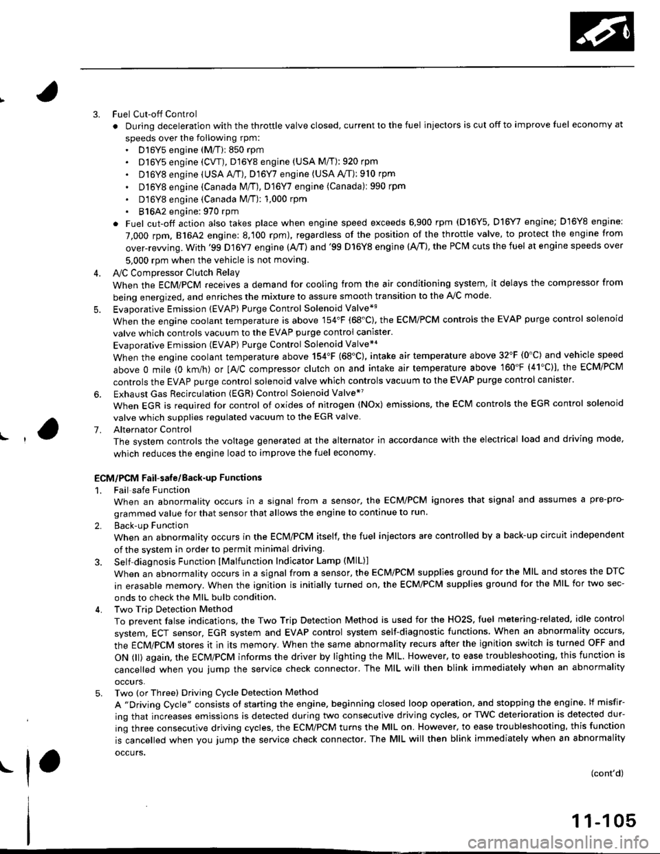
Fuel Cut-off Control
. During deceleration with the throttle valve closed, current to the fuel injectors is cut off to improve fuel economy at
speeds over the following rpm:. D16Y5 engine (M/T):850 rpm. D]6Y5 engine (CVT), D'16Y8 engine (USA M/T): 920 rpm
. Dl6Y8 engine (USA A,/I), D16Y7 engine (USA A,/T);910 rpm
. D16Y8 engine (Canada M/T), D16Y7 engine (canada): 990 rpm
' D16Y8 engine (Canada M/T): 1,000 rpm
. 816A2 engine: 970 rpm
. Fuel cut-off action also takes place when engine speed exceeds 6,900 rpm (D16Y5, D16Y7 engine; D'16Y8 engine:
7,000 rpm. 816A2 engine: 8.100 rpm), regardless of the position of the throttle valve, to protect the engine from
over-rewing. With '99 Dl6Y7 engine (A,/T) and '99 D16Y8 engine (A./T), the PCM cuts the fuel at engine speeds over
5,000 rpm when the vehicle is not moving.
IVC Compressor Clutch Relay
When the ECM/PCM receives a demand for cooling from the air conditioning system, it delays the compressor from
being energized, and enriches the mixture to assure smooth transition to the A,/C mode
Evaporative Emission (EVAP) Purge Control Solenoid Valve*'
When the engine coolant temperature is above 154'F (68'C). the ECM/PCM controls the EVAP purge control solenoid
valve which controls vacuum to the EVAP purge control canister.
Evaporative Emission (EVAP) Purge Control Solenoid Valve*a
When the engine coolant temperature above 154"F (68"C), intake air temperature above 32"F (0'C) and vehicle speed
above 0 mile (0 km/h) or [Ay'C compressor clutch on and intake air temperature above 160"F (41'C)], the ECM/PCM
controls the EVAP purge control solenoid valve which controls vacuum to the EVAP purge control canister.
Exhaust Gas Recirculation (EGR) Control Solenoid Valve*?
When EGR is required for control of oxides of nitrogen (NOx) emissions. the ECM controls the EGR control solenoid
valve which supplies regulated vacuum to the EGR valve
Alternator Control
The system controls the voltage generated at the alternator in accordance with the electrical load and driving mode,
which reduces the engine load to improve the fuel economy.
ECM/PCM Fail-safe/Back-up Functions
1. Fail safe Function
When an abnormality occurs in a signal from a sensor, the ECM/PCM ignores that signal and assumes a pre-pro-
grammed value for that sensor that allows the engine to continue to run.
2. Back-uD Function
When an abnormality occurs in the ECM/PCM itself, the fuel injectors are controlled by a back-up circuit independent
of the system in order to permit minimal driving.
3. Self diagnosis Function lMalfunction Indicator Lamp (MlL)l
When an abnormality occurs in a signal from a sensor, the ECM/PCM supplies ground for the lvllL and stores the DTC
in erasable memory. When the ignition is initially turned on, the ECM/PCM supplies ground for the MIL for two sec-
onds to check the MIL bulb condition.
4. Two Trip Detection Method
To prevent false indications, the Two Trip Detection Method is used for the HO2S, fuel metering-related. idle control
system, ECT sensor, EGR system and EVAP control system self-diagnostic functions. When an abnormality occurs,
the ECM/PCM stores it in its memory. When the same abnormality recurs after the ignition switch is turned OFF and
ON 0l) again, the ECM/PCM informs the driver by lighting the MlL. However, to ease troubleshooting, this function is
cancelled when you jump the service check connector. The MIL will then blink immediately when an abnormality
occurs,
5. Two (or Three) Driving Cycle Detection Method
A "Driving Cycle" consists ot starting the engine. beginning closed loop operation, and stopping the engine. lf misfir-
ing that increases emissions is detected during two consecutive driving cycles, or TWC deterioration is detected dur-
ing three consecutive driving cycles, the ECM/PCM turns the MIL on. However, to ease troubleshooting, this function
is cancelled when you jump the service check connector. The MIL will then blink immediately when an abnormality
occurs.
(cont'd)
1 1-1 05
.1.
Page 459 of 2189
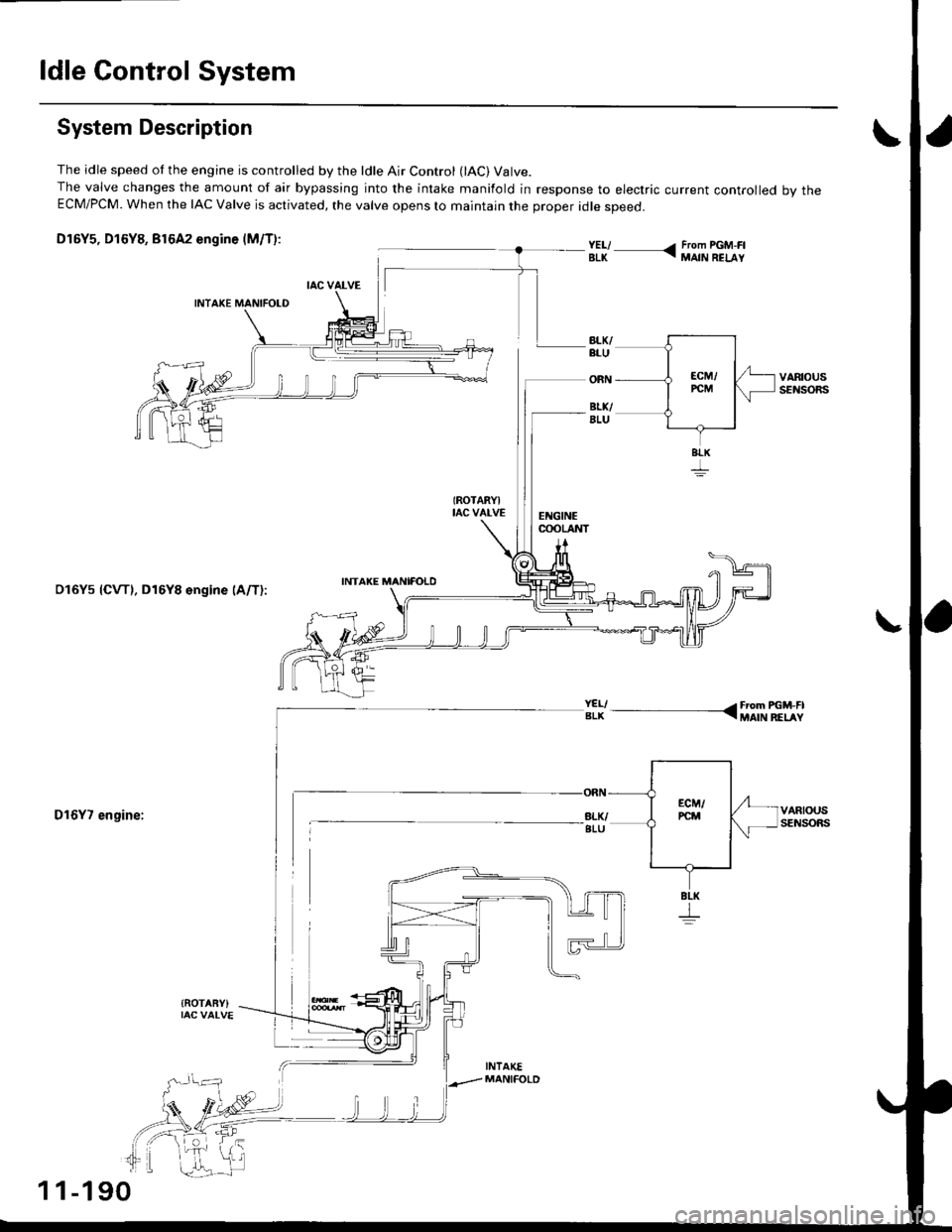
ldle Control System
System Description
The idle speed ot the engine is controlled by the ldle Air Control (lAC) Valve.The valve changes the amount of air bypassing into the intake manifold in response to electric current controlled bv theECM/PCM. When the IAC Valve is activated, the valve opens lo maintain the proper idle speed.
D16Y5, D16Y8, Br6A2 engine (M/T):
(ROTARYItac vat-vEEI{GINEcooLAI{T
VARIOUSsEI{SORS
VARIOUSSENSORS
INTAKE MANIFOTDDl6Ys {CVTl, D16Y8 engine lA/T):
D16Y7 engine:
{ROTABY)
;iy--, - ---
11-190
Page 461 of 2189
ldle Control System
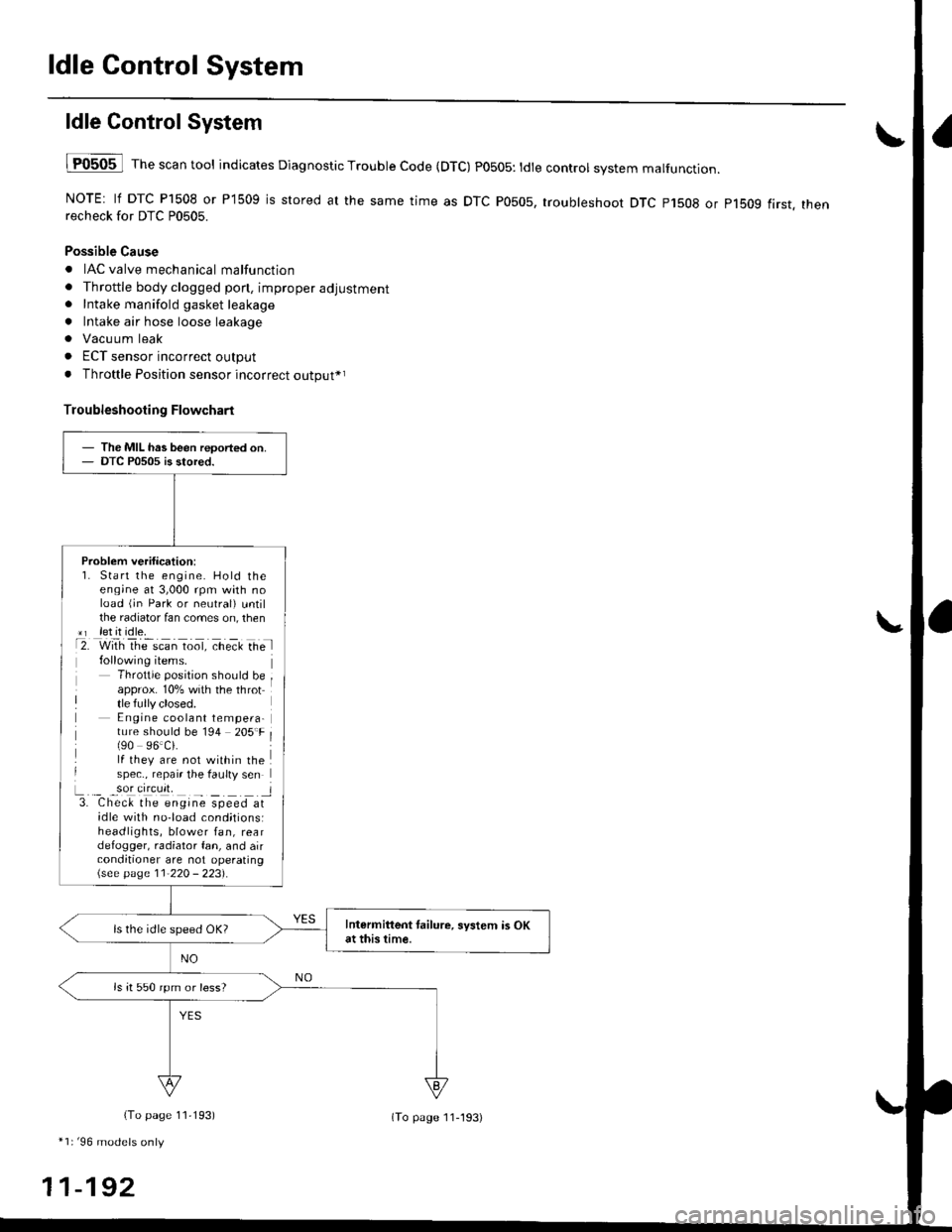
ldle ControlSystem
lF0505 l Th" """n tool indicates Diagnostic Trouble Code (DTC) PO5O5: tdte controt system malfunction.
NOTE: lf DTC P1508 or P1509 is stored at the same time as DTC P0505, troubleshoot DTC p1508 or p1bog first. thenrecheck for DTC P0505.
Possible Cause
. IAC valve mechanical malfunction
. Throttle body clogged pon, improper adjustment. Intake manifold gasket leakage
. Intake air hose loose leakage
. Vacu um leak
. ECT sensor incorrect output
. Throttle Position sensor incorrect output*r
Troubleshooting Flowchart
The MIL has been reoorted on.DTC P0505 is stored.
Problem verification:1. Start the engine. Hold theeng;ne at 3,000 rpm with noload (jn Park or neutral) untilthe radiator fan comes on, then*r let it idle.t2. with rhe scan toot, ct'eit Ge l
Throttle position should beapprox. 10% with the throttle fully closed.E ngine coolant tempera-ture should be 194 205'F(90 96.Ci.lf they are not within thespec., repair the faulty sen
L._ _9oI9[cr]41 l3. Chec& the engine speed atidle with no-load cond;tionsiheadlights, blower fan, reardefogger, radiator fan, and airconditioner are not operating\see page l1-22O - 223).
Intermittent tailure, system is OKat this time.ls the idle speed OK?
ls it 550 rpm or less?
(To page 11,193)
*1r'96 models only
11-192
(To page ll-193)
Page 463 of 2189
ldle Control System
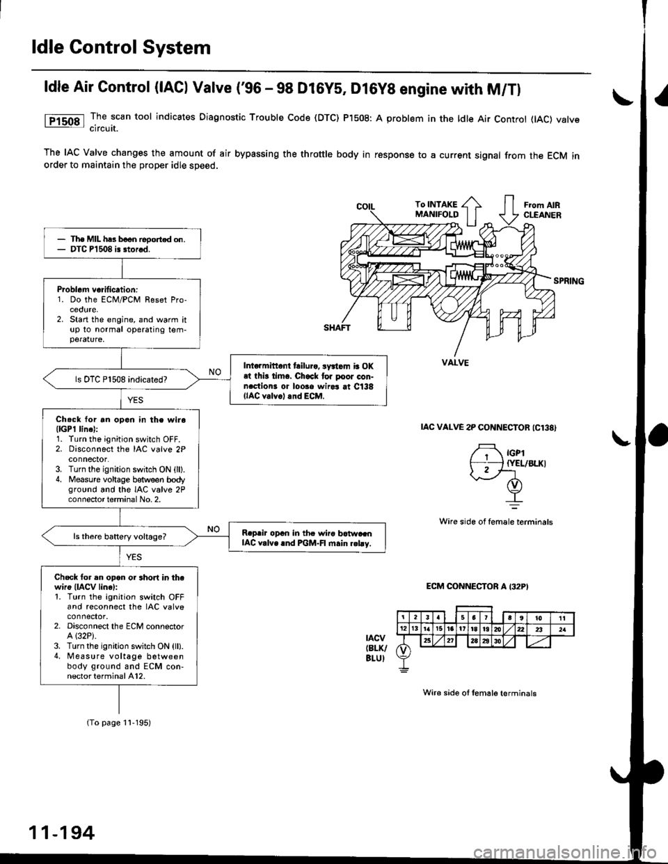
ldle Air Control (lACl Vatve ('96 - 98 Dl6ys, Dl6yB engine with M/Tl
The scan tool indicates Diagnostic Trouble Code (DTC) P1508: A problem in the ldle Air Controt flAC) varvecircuit.
The IAC Valve changes the amount of air bypassing the throttle body in response to a current signal from the ECM inorder to maintain the proper idle speed.
IAC VALVE 2P CONNECTOR ICl3A)
,flrcerh-:J iYEL/BLKI
!.__-,/ -lt(v)
-T-=
Wire side of female terminals
tAcv(BLK/
ELUI
ECM CONNECTOR A I32PI
Wire side oI lemal€ terminals
VALVE
6a10ll12t3r5t6l7t8t920232a
t*25&a2A3o
The MIL hss b€on repo.ted on.DTC P'l508 i. itorod.
Problem vorification:1. Do the ECM/PCM Reset Pro-cedure,Start the engine, and warm ituP to normal operating tem-perature.
Intormittont t!llur., sy.tcm b OKat thb tim6. Chsck fol poor con-ncctionr or loo3e wirot at C138(lAC valv.l.nd ECM.
ls DTC P1508 indicated?
Check for an opcn in the wiro(lGPl line):1. Turn the ignition switch OFF.2. Disconnect the IAC valve 2Pconnector.3. Turn the ignition switch ON (ll).
4. Measure vohage between bodyground and the IAC valve 2Pconnectorterminal No. 2.
R.prir opan in the wiro botwa.nIAC valv..nd PGM-FI main r.l.y.
Chock for an opon or sho in thewire (IACV linal:1. Turn the ignition switch OFFand reconnect the IAC valveconnector.2. Disconnect the ECM connectorA (32P).
3. Turn the ignit;on switch ON (ll).4. Measure voltage betweenbody ground and ECM con-nector terminal A12.
(To page 1l-195)
11-194