mat HONDA CIVIC 1999 6.G Workshop Manual
[x] Cancel search | Manufacturer: HONDA, Model Year: 1999, Model line: CIVIC, Model: HONDA CIVIC 1999 6.GPages: 2189, PDF Size: 69.39 MB
Page 1140 of 2189
Front Suspension
L
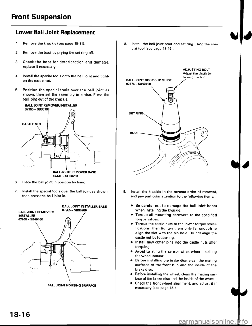
Lower Ball Joint Replacement
Remove the knuckle (see page 18-11).
Remove the boot by prying the set ring off.
Check the boot for deterioration and damage.
replace if necessary.
Install the special tools onto the ball joint and tight-
en the casfle nut.
Position the special tools over
shown. then set the assembly in
ball joint out of the knuckle,
BALL JOINT REMOVER/INSTALLER07965 - SB00r00
CASTLE NUT
the ball joint as
a vise. Press the
lf
7.
BALL JOINT REMOVER BASE07JAF - SH20200
Place the ball joint in position by hand.
Install the special tools over the ball joint as shown,
then press the ball joint in.
BALL JOINT INSTALLEB BASE07965 - 5800200
BALL JOINT HOUSING SURFACE
18-16
8. Install the ball joint boot and set ring using the spe-
cial tool (see page 18-16).
ADJUSTING BOLTAdjust rhe depth byturning the bolt.
Install the knuckle in the reverse order of removal,
and pay particular attention to the following items:
. Be careful not to damage the ball joint boots
when installing the knuckle,
. Torque all mounting hardware to the specified
torque values.
. Torque the castle nuts to the lower torque speci-
fications. then tighten them only far enough to
align the slot with the pin hole. Do not align the
castle nut by loosening.
. Install new cotter pins into the castle nuts after
torquang.
. Avoid twisting the sensor wires when installing
the wheel sensor.
. Before installing the brake disc. clean the mating
surfaces of the front hub and the inside of the
brake disc.
. Before installing the wheel, clean the mating sur-
face of the brake disc and the inside of the wheel.. Check the front wheel alignment, and adjust it if
necessary {see page 18-4).
Page 1141 of 2189
Front Damper
!Ball Joint Boot RePlacement
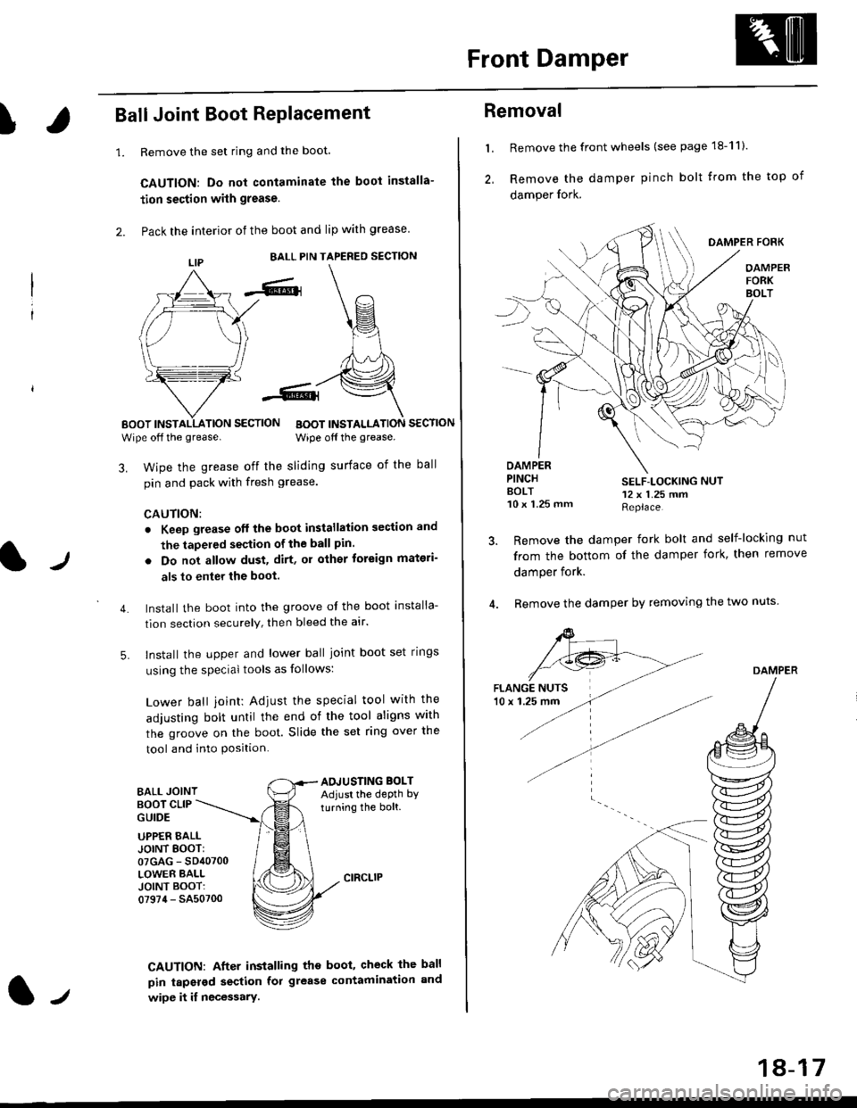
1.Remove the set ring and the boot.
CAUTION: Do not contaminate the boot installa-
tion section with grease.
Pack the interior of the boot and lip with grease
EALL PIN TAPERED SECTION
EOOT INSTALLATION SECTION
Wipe off the grease.BOOT INSTALLATION SECTION
Wipe off the grease.
lJ
3. Wipe the grease off the sliding surface of the ball
pin and pack with fresh grease.
CAUTION:
. Keep grease off the boot installation section and
the tapeled section of the ball pin.
5.
. Do not allow dust, dirt, or other toreign materi-
als to enter the boot.
Install the boot into the groove of the boot installa-
tion section securely, then bleed the atr.
Install the upper and lower ball joint boot set rings
using the special tools as follows:
Lower ball joint: Adiust the special tool with the
adjusting bolt until the end of the tool aligns with
the groove on the boot. Slide the set ring over the
tool and into Position.
BALL JOINTAOJUSTING BOLTAdjust the depth by
turning the bolt.BOOT CLIPGUIDE
4.
UPPER EALLJOINT EOOT:07GAG - SD40700LOWER BALLJOINT BOOT:07974 - SA50700
CAUTION: After installing the boot, check the ball
pin tapsrod section fol grease contamination and
wipe it if necessary.lt
18-17
Removal
l. Remove the front wheels (see page 18-11).
2, Remove the damper pinch bolt trom the top of
damper fork.
DAMPER FORK
OAMPERFORKBOLT
OAMPERPINCHAOLT10 x 1.25 mm
SELF-LOCKING NUT12 x 1.25 mmReplace.
Remove the damper fork bolt and self-locking nut
from the bottom of the damper fork, then remove
damper fork.
Remove the damper by removing the two nuts
DAMPER
Page 1147 of 2189
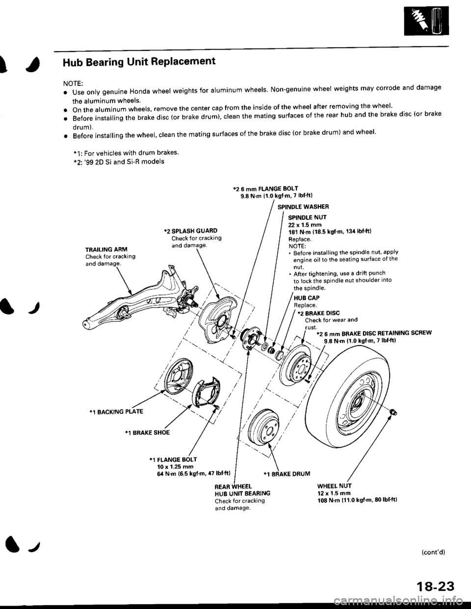
IHub Bearing Unit RePlacement
For vehicles with drum brakes.'99 2D Si and Si-B models
NOTE:
o Use only genuine Honda wheel weights for aluminum wheels Non-genuine wheel weights may corrode and damage
the aluminum wheels.
.onthea|uminumwhee|s,removethecentercapfromtheinsideoftheWhee|afterremovingthewhee|'
. Before insta||ing the brake disc (or brake drum), c|ean the mating surfaces of the rear hub and the brake disc (or brake
orum,.
. Before installing the wheel, clean the mating surfaces ofthe brake disc(or brake drum) andwheel'
*1:
*2'.
12 6 mm FLANGE BOLT
9.8 N.m {1.0 kgf m, 7 lbf'ft|
*2 SPLASH GUAROCheck for crackingand damage.
SPINDLE WASTIER
SPINDLE NUT
22 x 1.5 mm181 N,m (18.5 kgt'm. 134lbfft)
Replace.NOTE:' Before installing the spindle nut, apply
engine oil to the seating surface of the
nut,' After tightening, use a drift Punchto lock the spindle nut shoulder into
TRAILING ARMCheck for crackingand oamage,
lr
the spindle.
HUB CAPBeplace.12 BRAKE DISCCheck for wear and
rust,'2 6 mm BRAKE DISC RETAINING SCREW
9.8 N'm 11.0 kgt m, 7 lbf'ft|
)
*1 BACKING PLATE
/\*1 BRAKE SHOE
r1 FLANGE BOLT10 x 1.25 mm6,0 N.m (6.5 ksl.m,47 lbl'ftl
REAB
'1 BRAKE ORUM
HUB UNIT BEARING
Check for crackingand damage.
WHEEL NUT12 x 1.5 mm108 N.m {11.0 kgt'm.80lbt'ft)
(cont'd)
1A-23
l-t
Page 1161 of 2189
I
Bleeding
CAUTION:
. Always use Genuine Honda DOT 3 Brake Fluid. Using 8
non-Honda brak€ fluid can cause corrosion and
docrea3e the life of the system.
. Make surs ||o dirt or other foteign matter is allowed
to contaminate the brake fluid,
. Do not spill brake lluid on the vehicle, it may damago
the paint; if brake lluid doos contac{ the paint, wash
it ofl imm€diately with water.
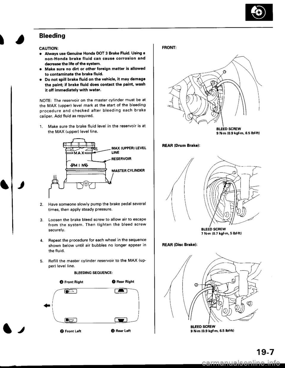
NOTE: The reservoir on the master cylinder must be at
the MAX (upper) level mark at the start of the bleeding
procedure and checked after bleeding each brake
caliper. Add fluid as required.
1. Make sure the brake fluid level in the reservoir is at
the MAX lupper) level line.
MAX {UPPER) LEVEL
CYLINDER
Have someone slowly pump the brake pedsl several
times, then apply steady Pressure.
Loosen the brake bleed screw to allow air to escape
from the system. Then tighten the bleed screw
securely.
Repeat the procedure for each wheel in the sequence
shown below until air bubbles no longer appear in
the fluid.
Refill the master cylinder reservoir to the MAX (up-
per) level line.
ELEEDING SEOUENCE:
O Front Right(D Bo.r Right
O Front LeftO Rear Left1,,
19-7
FRONTT
REAR lDrum Brakel:
REAR (Disc Brake):
AIEED SCREW9 N.m (0.9 ksf m, 6.5 lbf'ft)
Page 1166 of 2189
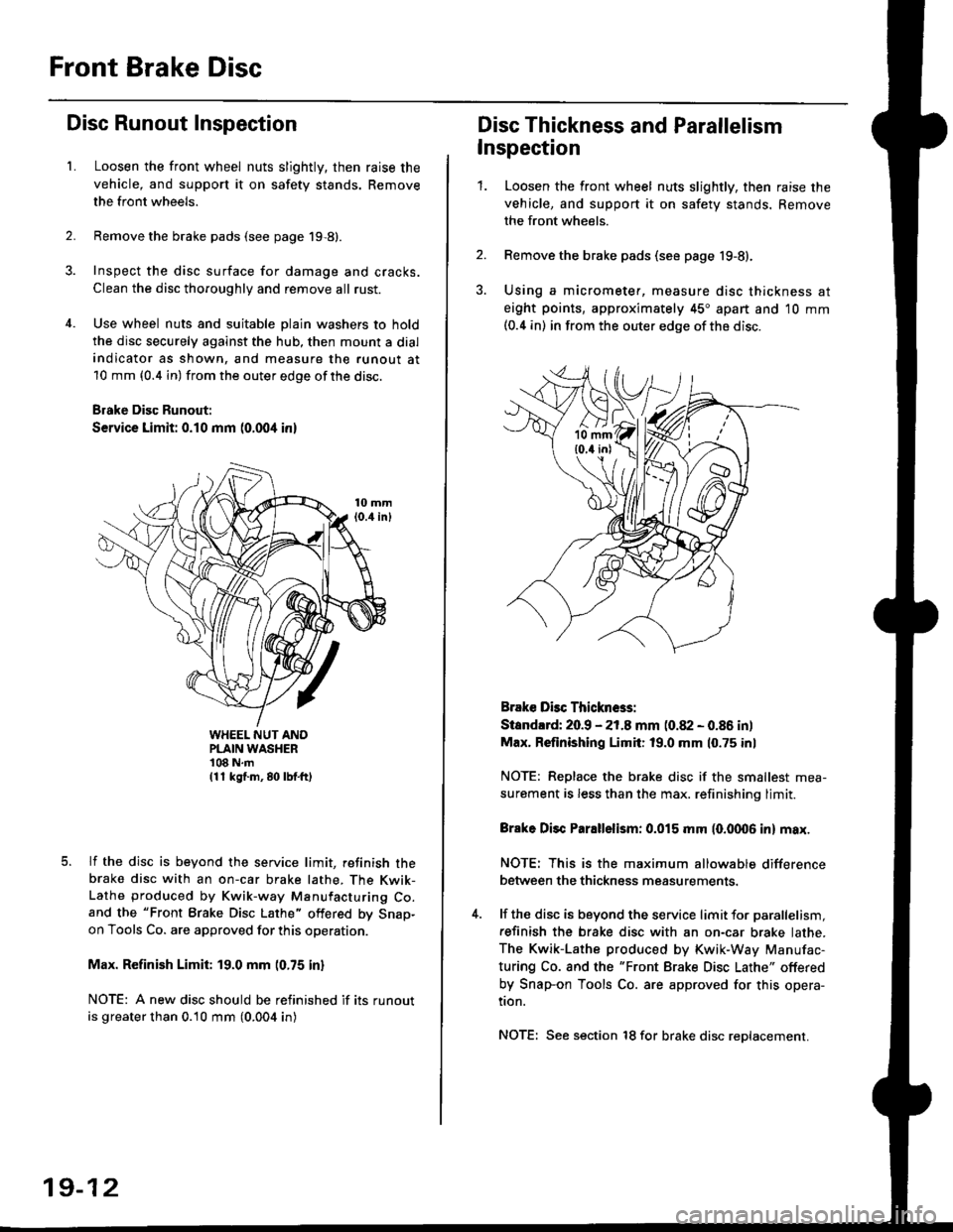
Front Brake Disc
Disc Runout Inspection
L
2.
Loosen the front wheel nuts slightly, then raise the
vehicle, and support it on safety stands. Remove
the front wheels.
Remove the brake pads (see page 19,8).
Inspect the disc surface for damage and cracks.
Clean the disc thoroughly and remove all rust.
Use wheel nuts and suitable plain washers to hold
the disc securely against the hub, then mount a dial
indicator as shown, and measure the runout at
10 mm (0.4 in) from the outer edge of the disc.
Brake Disc Runout:
Service Limit: 0.10 mm (0.004 inl
WHEEL NUT ANOPLAIN WASHER'108 N.m(11 kg{.m, 80 lbf.ft)
lf the disc is beyond the service limit, refinish thebrake disc with an on-car brake lathe, The Kwik-Lathe produced by Kwik-way Manufacturing Co.and the "Front Brake Disc Lathe" offered by Snap-on Tools Co. are approved for this operation.
Max. Refinish Limit: 19.0 mm (0.75 in)
NOTE: A new disc should be refinished if its runout
is greater than 0.10 mm (0.004 in)
19-12
Disc Thickness and Parallelism
Inspection
1.Loosen the front wheel nuts slightly, then raise the
vehicle, and support it on safety stands. Remove
the front wheels.
Remove the brake pads (see page 19-8).
Using a micrometer, measure disc thickness at
eight points, approximately 45" apart and 10 mm(0.4 in) in from the outer edge of the disc.
Brake Dbc Thickn6s:
Standlrd: 20.9 - 21.8 mm (0.82 - 0.86 in)
Max. Refinishing Limit: 19.0 mm 10.75 inl
NOTE: Replace the brake disc if the smallest mea-
surement is less than the max. refinishinq limit.
Brake Disc Parallelism: 0.015 mm (0.fit06 in) max.
NOTE: This is the maximum allowable difference
between the thickness measurements.
lf the disc is beyond the service limit for parallelism,
refinish the brake disc with an on-car brake lathe.
The Kwik-Lathe produced by Kwik-Way Manufac-
turing Co. and the "Front Brake Disc Lathe" offered
by Snap-on Tools Co. are approved for this opera-
tion.
NOTE: See section 18 for brake disc reDlacement.
Page 1170 of 2189
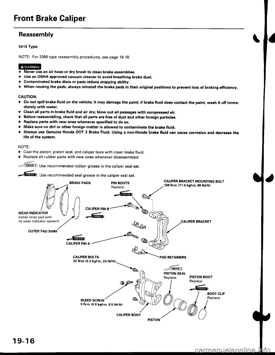
Front Brake Galiper
Reassembly
5410 Type:
NOTE: For 2056 type reassembly procedures, see page 19-18.
o Never use an air hose or dry brush to clean brako assemblies.. Use an OSHA approved vacuum cleanerto avoid breathing brake dust.. Contaminated brake discs or pads reduce stopping abilhy.. when reusing the pads, always reinstall the brake pads in their original positions to pr€vent loss of braking €fficiency.
CAUTION:
. Do not spill brake fluid on the vehicle; it may damage the paint; if brake fluid do€s contaci the psint, wash it oft imme"diately with water.
. Clean all parts in brake fluid and air dry; blow out all passag€s whh comp.€ssed air.. Betore reassembling, check that all parts are free ol dust and othor toreign particlos.
. Replace parts wilh new ones whenever specified to do so.. Make sure no dirt or other toreign matt€r is allowed to contaminate the brake fluid.. Always use Genuine Honda DOT 3 Brake Fluid. Using a non.Honda brake tluid can cause corrosion and decresse thelife of th€ system.
NOTE:
. Coat the piston, piston seal, and caliper bore with clean brake fluid.. Replace all rubber parts with new ones whenever disassembled.
z_..=-.q8! .9!,H: Use recommended rubber grease in the caliper seal set.
-.61' use recommended seal grease in the catiper seal set.
BRAKE PADSPIN BOOTSReplace.
OUTER PAD SHIM
-o -'''---&@CAI-IPER PIN A -
BLEED SCREWS N.m (0.9 kgt.m, 6.5 tbf.ftl
"k..6
*/\*
car-rpen prr'r e-....,-q\,
-W@{
q
1
PAD RETAINERS
CALIPER BRACKET
WEAB INDICATOR
tilfliltn
tw tfi lJlWEAB rNDrcAroR \J I Ilnsrall inner pad with lAVirs weat indicatot !pwatd/,.
CALIPER BRACKEI MOUNTING BOLT108 N.m {11.0 kgt m,80lbf.ft)
PISTON BOOTReplace.
-6r
/ eoor cr-re
I neptace.
6/vo
PISTON SEALReplace.
19-16
CALIPER BODY
Page 1172 of 2189
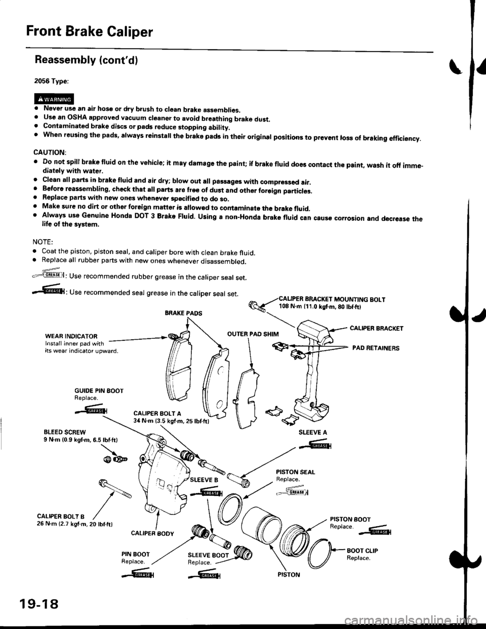
Front Brake Caliper
Reassembly (cont'd)
2056 Type:
. Never use an air hose or dry b.ush to clean brake assemblies.. Uso an OSHA approved vacuum cleansr to avoid breathing brake dust.. Contaminated brake discs or pads reduce stopping ability.t when reusing the pads, always r6instsll the brake pads in their original positioos to prevent loss ol braking efficiency.
CAUTION:
' Do not spill brake tluid or th€ vehicle; it m8y damage the paint; if brake fluid does contact the paint, wash it off imme-diately with water.
. Clean all parts in brake tluid and air dry; blow out all passages with compr63ed air.. Beforo reassembling, check that all parts are fr€e of dust and other foreign particles,. Replace parts with new ones whenevea specified to do so.. Make sure no dirt or other foreign matter is allowad to contaminato the brake fluid,' Always use Genuine Honda DOT 3 Brake Fluid. Using a non-Honda brake fluid can caus€ corrosior and decrease thelife ol the system.
NOTE:
. Coat the piston, piston seal, and caliper bore with clean brake fluid.. Replaceall rubber parts with new ones whenever disassembled.
.'=5@: Use recommended rubber grease in the caliper seal set,
-6l ' Use recommended seal grease In the caliper seal set.
@6--i#i['i,?li"..;:l]l?Y]li"'"'
I
r""'"rr r"""ip"autr, -/ffr
e"6ft 'ADRETATNERSitswearndcatoru'ward
MffiA pr
GUIDE PIN BOOT ) {I I II ) I I
% caL,PER
\I\d/ tt ' id 6
u -es'---r..'.* ".-,."oo*'J.l, ru,oonW U
**=*t
WEAR,INDICAToR. ,ffi OUTERIPAD
BLEED SCREW9 N.m (0.9 kgf.m, 6.5 lbf.ft)
\o@
CALIPER BRACKET
PISTON EOOTReplace. -.&l
BOOT CLIPReplace.
SLEEVE A
SLEEVE 8
-"-41
r{.i'""Jg*'
a,t/ c'f3!@
q.-
t\
20 tbf.ftl
CALIPER BOLT B26Nm{2.7kgf.m,
CALIPER BODY
PIN BOOTReplace.
BRAKE PAOS
19-18
Page 1177 of 2189
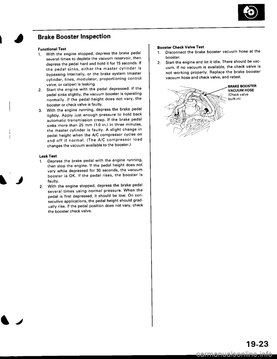
Brake Booster InsPection
FunctionalTest
1. With the engine stopped, depress the brake pedal
several times to deplete the vacuum reservoir, then
depress the pedal hard and hold it for 15 seconds lf
the pedal sinks' either the master cYlinder is
bypassing internally, or the brake system (master
cylinder. lines. modulator, proportioning control
valve, or caliPer) is ieaking.
2. Start the engine with the pedal depressed lf the
pedal sinks slightly, the vacuum booster is operating
normally. lf the pedal height does not vary, the
booster or check valve is faultY.
3. With the engine running. depress the brake pedal
lightly. Apply just enough pressure to hold back
automatic transmission creep. lf the brake pedal
sinks more than 25 mm (1.0 in.) in three minutes,
the master cvlinder is faulty. A slight change in
pedal height when the A'lC compressor cycles on
and off if normal. (The A/C compressor load
changes the vacuum available to the booster')
Leak Test
1. Depress the brake pedal with the engine running.
then stop the engine. lf the pedal height does not
vary while depressed for 30 seconds, the vacuum
booster is OK. lf the pedal rises. the booster is
faulty.
2, With the engine stopped, depress the brake pedal
several times using normal pressure When the
Dedal is first depressed, it should be low On con-
secutive applications, the pedal height should grad-
uallv rise. lf the pedal position does not vary, checK
the booster check valve.
l./
19-23
Booster Check Valve Test
1. Disconnect the brake booster vacuum hose at the
booster.
2. Stan the engine and let it idle. There should be vac-
uum. lf no vacuum is available, the check valve is
not working properly. Replace the brake booster
vacuum hose and check valve, and retest.
BRAKE BOOSTERVACUUM HOSE(Check valve
built-in)
Page 1180 of 2189
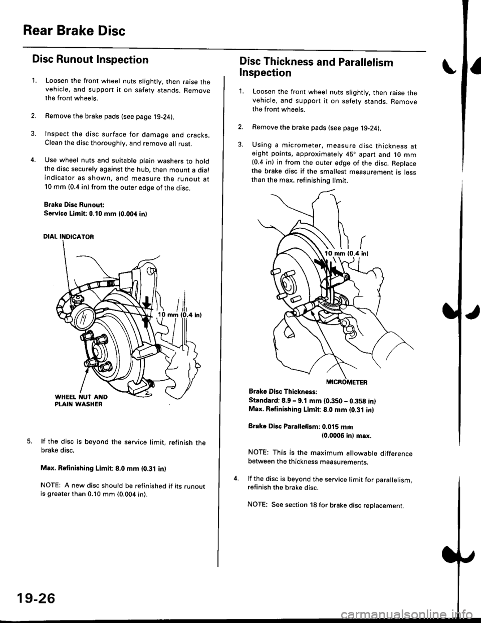
Rear Brake Disc
Disc Runout Inspection
1.Loosen the front wheel nuts slightly, then raise thevehicle, and suppon it on safety stands. Removethe front wheels.
Remove the brake pads (see page 19-24).
Inspect the disc surface for damage and cracks.Clean the disc thoaoughly, and remove a
rust.
Use wheel nuts and suitable plain washers to holdthe disc securely against the hub. then mount a dialindicator as shown. and measure the runout at10 mm (0.4 in) from the outer edge of the disc.
Brake Disc Runout:
Service Limit:0.10 mm {0.00,t in)
5. lf the disc is beyond the service limit, refinish thebrake disc,
Max. Retinishing Limit: 8.0 mm {0.31 in)
NOTE: A new disc should be refinished if its runoutis greater than 0.10 mm (0.004 in).
19-26
Disc Thickness and Parallelism
Inspection
1. Loosen the front wheel nuts slightly, then raise thevehicle, and support it on safety stands. Removethe front wh6els.
2. Remove the brake pads (see page j9-24).
3. Using a micrometer. measure disc thickness aterght points, approximately 45" apart and 1o mm{0.4 in) in from the outer edge of the disc. Replacethe brake disc if the smallest measurement is lessthan the max. refinishing limit.
Brake Disc Thickness:
Standard: 8.9 - 9.1 mm (0.350 - 0.358 in)Max. Rsfinishing Limit: 8.0 mm {0.31 in}
Brake Disc Parallelirm: 0.015 mm(0.0006 inl msx.
NOTE; This is the maximum allowable differencebetween the thickness measurements.
4. lf the disc is beyond the service limit for Darallelism.refinish the brake disc.
NOTE; See section 18 for brake disc replacement.
Page 1185 of 2189
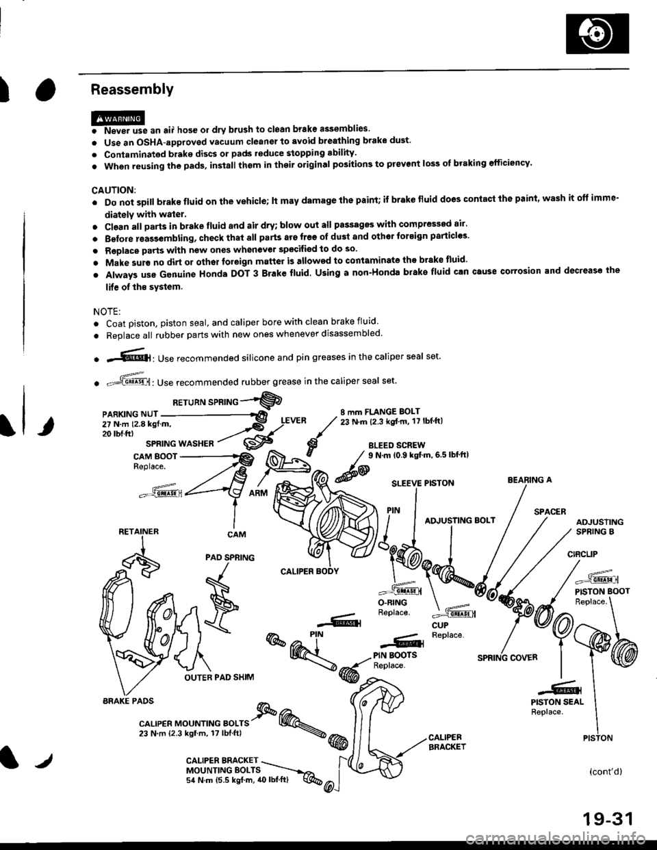
IReassembly
HP* "n ",, hos6 or drv brush to ctoan brake assemblies.
o Use an OSHA-approved vacuum cleanel to avoid brealhing brake dust'
. Contaminated brake discs or pads reduce stopping sbility.
. When reusing the pads, in3tall thom in thoil original positions to prevent loss of braking efficiency'
CAUTION:
. Do not soill brake fluid on the vehicle; lt may damage lhe paint; if brake fluid does contacl the paint' wash it oft imme-
diately with water.
. Cl€an all Darts in brake fluid and air dry; blow out all passagss with comPressed air'
. Belore rsas3embling, check that all parts ars free ot du3t and othor tor€ign particles'
. Replace parts with new ones whenever spscifiod to do so.
o Make sur€ no dirt or othor foreign matter is allowed to contaminate the brake tluid'
. Always use Genuine Honda DOT 3 Brake fluid. Using a non-Honda brake fluid can Gtuse corrosion and decrease the
lif€ of ths system.
NOTE:
. Coat piston, piston seal, and caliper bore with clean brake fluid
. Replace all rubber parts with new ones whenever disassembled.
o .-'{@]: Use recommended silicone and pin greases in the caliper seal set.
. -ffi,Use recommended rubber grease in the caliper seal set.
RETuRN sPRTNG -"'9
8 mm FLANGE BOLT23 N.m (2.3 kgt'm, 17 lbf ftl
BLEED SCREW
@
9 N.m (0.9 kgtm,6.5lbf'ft|
CUP
=^.
PISTON BOOT
(cont'd)
19-31
BEARING A
PAO SPNING
F
\
OUTER PAD SHIM
r--- Replace..ffiPIN BOOTSReplace.
-61
@@-t-.
"l-r,r., "or"'*o " orr" I @.,23 N.m {2.3 kgtm, 17lbf.ftl \@
PISTON SEALReplace.
CALIPEBBRACKET
iiilji:ll;;
__X.,,..".^
BRAKE PAOS
PISTON
l/CALIPER BMCKET \MOUNTINGEOLTS ----.-,o,
54 N.m (5.5 kgf.m, 40lbl.ft) q%