Body HONDA CIVIC 1999 6.G Workshop Manual
[x] Cancel search | Manufacturer: HONDA, Model Year: 1999, Model line: CIVIC, Model: HONDA CIVIC 1999 6.GPages: 2189, PDF Size: 69.39 MB
Page 781 of 2189
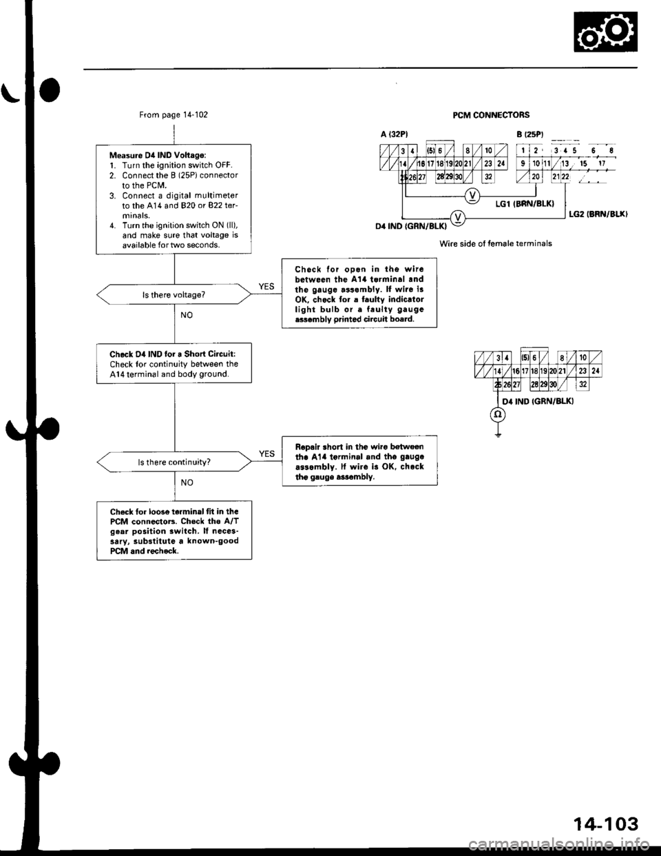
From page 14-102
Measu.e D4 IND Voltago:1. Turn the ignition switch OFF.2. Connect the B (2SPiconnector
to the PCM.3. Connect a digital multimeter
to the A14 and 820 or 822 ter-
4. Turn the ignition switch ON (ll),
and make sure that voltage isavailable for two seconds.
Chock for ooon in tho witebetween the A't4 tsrminal .ndthe gauge.3s.mbly. ll wite i3OK, chock to. a t.ulty indicatorlight bulb or. feulty gaugc
e336mbly p.inted circuit board.
Check D4 IND lor a Short Citcuit:Check lor continuity between theA14 terminal and body ground.
Rop.ir short in thc wirg b€twoenth. Al4 tormin.l .nd tho gaugo
a$ombly. ll wiro is OK. chocktho gsugo a3rambly.
ls there continuity?
Check fo. loose terminal tit in thcPCM connectoB. Chock the A/Tgear position switch. It ncce3-sary, substitute a known-goodPCM and rechock.
PCM CONNECTORS
Wire side ol female terminals
14-103
Page 783 of 2189
Lock-up Gontrol Solenoid Valve A/B Assembly
Test
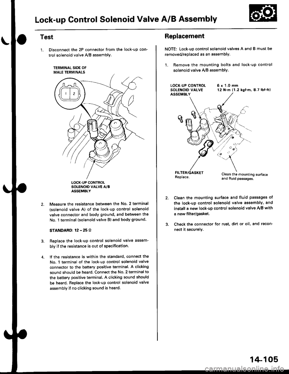
'1, Disconnect the 2P connector from the
trol solenoid valve 1y'8 assembly.
TERMINAL SIOE OF
MALE TERMINALS
tocK-up con-
LOCK.UP CONTROLSOLENOID VALVE A/BASSEMBLY
Measure the resistance between the No. 2 terminal
(solenoid valve A) of the lock-up control solenoid
valve connector and body ground, and between the
No. 1 terminal (solenoid valve Bl and body ground.
STANDARD: 12 - 25 O
Replace the lock-up control solenoid valve assem-
bly if the resistance is out of specification.
lf the resistance is within the standard, connect the
No. 1 terminal of the lock-up control solenoid valve
connector to the battery positive terminal. A clicking
sound should be heard. Connsct the No. 2 terminal to
the battery positive terminal. A clicking sound should
be heard. Replace the lock-up control solenoid valve
assembly if no clicking sound is heard.
Replacement
NOTE: Lock-up control solenoid valves A and I must bs
removed/replaced as an assembly.
1. Remove the mounting bolts and lock-up control
solenoid valve Ay'B assemblv.
6 r 1.0 mm12 N.m (1.2 kgf.m,8.7 lbl.ftl
/:'-
Clean the mounting surfaceand fluid psssages.
Clean the mounting surface and fluid passages of
th6 lock-up control solenoid valve assembly, and
instsll a new lock-up control sol€noid valve Ay'B with
a new filtsr/gask€t.
Check the connector for rust, dirt or oil, and racon-
nect it securely.
1+105
Page 784 of 2189
Shift Control Solenoid Valve A/B Assembly
Test
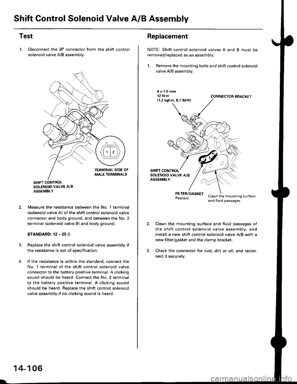
1. Disconnect the 2P connector from the shift control
solenoid valve A,/B assemblv.
SHIFT CONTROLSOLENOID VALVE A/B
ASSEMBLY
N4easure the resistance between the No. 1 terminal(solenoid valve A) of the shift control solenoid valve
connector and body ground, and between the No. 2
terminal (solenoid valve B) and body ground.
STANDARD: 12 - 25 O
Replace the shift control solenoid valve assembly if
the resistance is out of specification,
lf the resistance is within the standard, connect the
No. 1 te.minal of the shift control solenoid valve
connector to the battery positive terminal. A clicking
sound should be heard. Connect the No. 2 terminal
to the battery positive terminal. A clicking sound
should be heard. Replace the shift control solenoid
valve assembly if no clicking sound is heard.
14-106
Replacement
NOTE: Shift control solenoid valves A and B must be
removed/replaced as an assembly.
1. Remove the mounting bolts and shift control solenoid
valve A,/B assembly.
5xL0mm12 N.m(1.2 kgf.m,8.7 lbf.ft)CONNECTOR BRACKET
FILTER/GASKETBeplace.Clean the mounting surfaceand fluid passages.
Clean the mounting surface and fluid passages of
the shift control solenoid valve assembly, and
install a new shift control solenoid valve Ay'B with a
new filter/gasket and the clamp bracket.
Check the connector for rust. dirt or oil. and recon-
nect it securelv,
Page 790 of 2189
Symptom-to-Component Chart
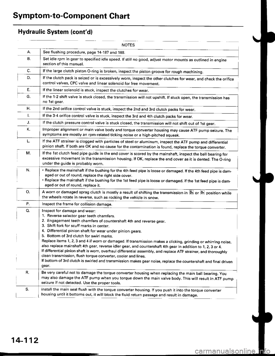
Hydraulic System (cont'dl
G.
n,
set idle rpm in gear to specified idle speed. lf still no good, adjust motor mounts as outlined in enginesection of this manual.
lf the clutch pack is seized or is excessively worn. inspect the other clutches for wear, and check the orificecontrol valves, CPC valve and linear solenoid for free movement.
lf the linear solenoid is stuck, inspect the clutches for wear.
lmproper alignment or main valve body and torque converter housing may cause ATF pump seizure. Thesymptoms are mostly an rpm-related ticking noise or a high-pitched squeak.
lf the l st clutch feed pipe guide in the end cover is scored by the mainshaft, inspect the ball bearing forexcessive movement in the transmission housing. lf oK, replace the end cover as it is dented. The o-rinounder the guide is probably worn.
Replace the mainshaft if the bushing for the 4th feed pipe is loose or damaged. lf the 4th feed pipe is danFaged or out of round, replace the right side cover.
Replace the mainshaft if the bushing for the 1st feed pipe is loose or damaged. lf the 1st feed pipe is darn-aged or out of round, replace it.
A worn or damaged sprag clutch is mostly a result of shifting the transmission inthe wheels rotate in reverse, such as rocking the vehicle in snow.
or E position while
Inspect for damage and wear:
1. Reverse selector gear teeth chamfers.
2. Engagement teeth chamfers of countershaft 4th and reverse gear.
3. Shift fork for scuff marks in center.
4. Differential pinion shaft for wear u nder pin ion gears.
5. Bottom of 3rd clutch for swirl marks.
Replace items 1,2,3 and 4 if worn or damaged. lf transmission makes a clicking, grinding orwhirring noise,also replace mainshaft 4th gear, reverse idler gear. and countershaft 4th gear in addition to 1, 2, 3 or 4.lf differential pinion shaft is worn, overhaul differential assembly, and replace ATF strainer, and thoroughlyclean transmission, flush torque converter, cooler and lines.lf bottom of 3rd clutch is swirled and transmission makes gear noise, replace the countershaft and final drivengear.
Be very careful not to damage the torque converter housing when replacing the main ball bearing, you
may also damage the ATF pump when you torque down the main valve body. This will result in ATF pumpseizure if not detected. Use the oroper roors.
Install the main seal flush with the torque converter housing. lf you push it into the torque converterhousing until it bottoms out, it will block the fluid return passage and result in damage.
See flushing procedure, page 14-187 and 188.
lf the large clutch piston O-ring is broken, inspect the piston groove for rough machining.
lf the l-2 shift valve is stuck closed, the transmission will not upshift. lf stuck open, the transmission hasno 1st gear.
lf the znd orifice control valve is stuck. inspect the 2nd and 3rd clutch oacks for wear.
lf the 3-4 orifice control valve is stuck, inspect the 3rd and 4th clutch oacks for wear.
lf the clutch pressure control valve is stuck closed, the transmission will not shift out of 1st gear.
lf the ATF strainer is clogged with particles of steel or aluminum, inspect the ATF pump and differentialpinion shaft. lf both are OK and no cause for the contamination is found, replace the torque converter.
Inspect the frame for collision damage.
14-112
Page 808 of 2189
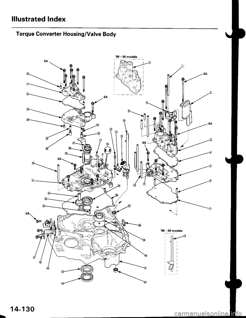
lllustrated lndex
Torque Converter Housing/Valve Body
to\
\*
L
14-130
Page 809 of 2189
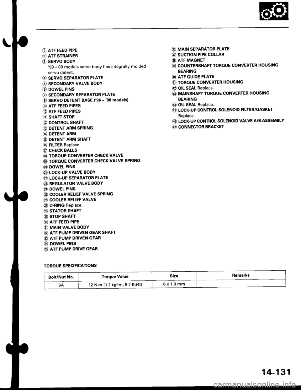
O ATF FEED PIPE
O ATF STRAINER
O SERVO BODY'99 - 00 models servo body has integrally molded
servo detent.
@ SERVO SEPARATOR PLATE
(' SECONDARY VALVE BODY
@ DOWEL P|NS
O SECONDARY SEPARATOR PLATE
@ SERVO DETENT BASE ('�96 -'98 models)
O ATF FEED PIPES
(D ATF FEED PIPES
O SHAFT STOP
@ CONTROL SHAFT
€D DETENT ARM SPRING
@ DETENT ARM
(9 DETENT ARM SHAFT
@ FILTER Replace.
(? CHECK BALLS
@ TOROUE CONVERTER CHECK VALVE
@ TOROUE CONVERTER CHECK VALVE SPRING
@ DOWEL PINS
@ LOCK.UP VALVE BODY
@ LOCK-UP SEPARATOR PLATE
@ REGULATOR VALVE BODY
@} DOWEL PINS
@ COOLER RELIEF VALVE SPRING
@ COOLER RELIEF VALVE
@ O-RING Replace.
@ STATOR SHAFT
@ STOP SHAFT
@ ATF FEED PIPE
@ MAIN VALVE BODY
@ ATF PUMP DRIVEN GEAR SHAFT
@ ATF PUMP DRIVEN GEAR
@ DOWEL PINS
65) ATF PUMP DRIVE GEAR
@ MAIN SEPARATOR PLATE
@ SUCTION PIPE COLLAR
@ ATF MAGNET
@ COUNTERSHAFT TOROUE CONVERTER HOUSING
BEARING
@ ATF GUIDE PLATE
@ ToRoUE CONVERTER HOUSING
@ OIL SEAL Replace.
@ MAINSHAFT TOROUE CONVERTER HOUSING
BEARING
@) olL SEAL Replace.
@ LOCK-UP CONTROL SOLENOID FILTER/GASKET
Reolace.
@ LOCK-UP CONIROL SOLENOID VALVE A/B ASSEMELY
@ CONNECTOR BRACKET
TOROUE SPECIFICANONS
Bolt/Nut No.Torque ValugSiz€Remarkg
12 N.m (1.2 kgf.m,8.7 lbnft)6x1,0mm
14-131
Page 814 of 2189
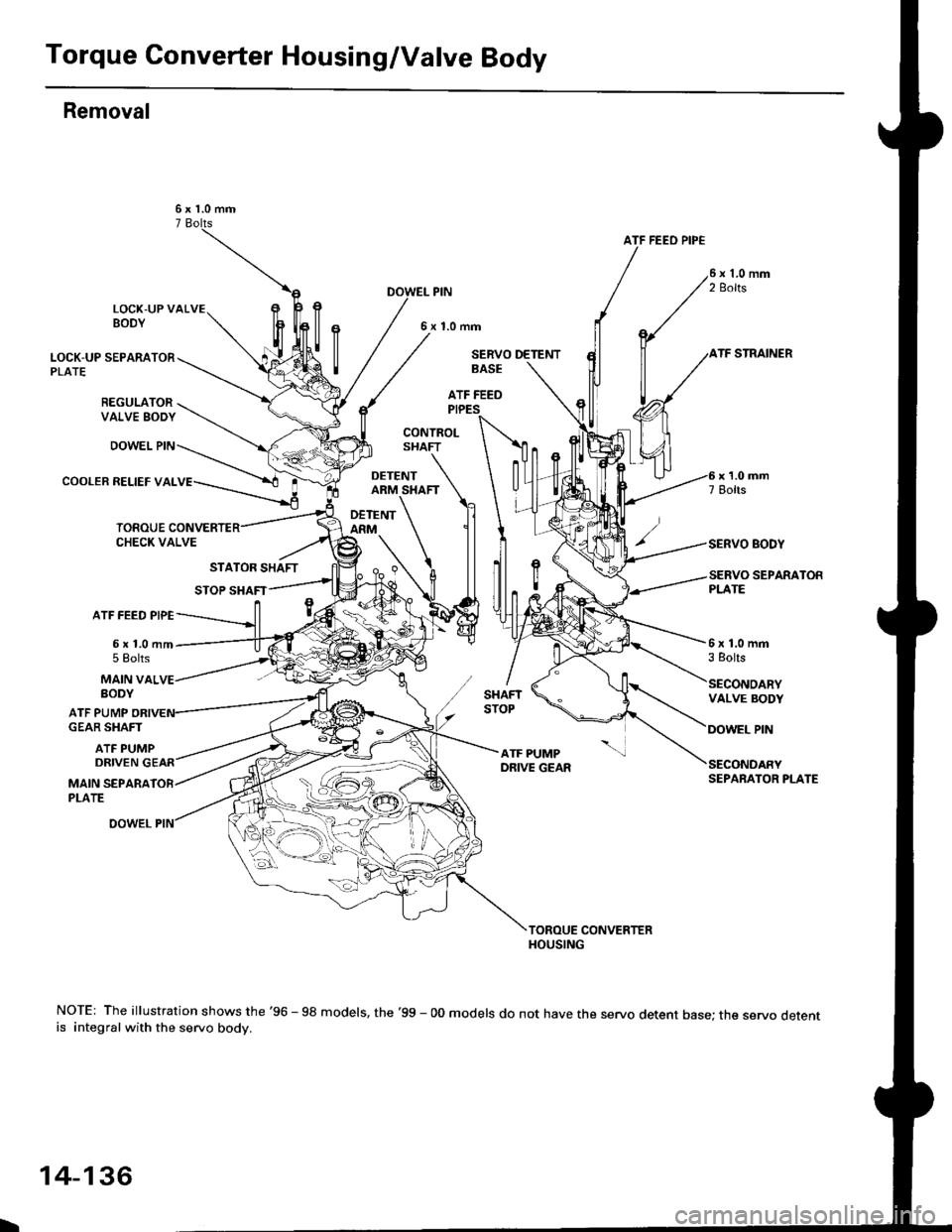
Torque Converter Housing/Valve Body
Removal
ATF FEEO PIP€
LOCK-UP VALVEBODY
PIN
6x1.0mm
LOCK-UP SEPARATORPLATE
REGULATORVALVE SODY
DOWEL PIN
COOLER RELIEF VAL
SERVO DETENTSTRAINER
SERVO EODY
SEPARATON
BASE
ATF FEEDPIPES
CONTROLSHAFT
DETENTARM SHAFT
DETENTARM
ATF FEED PIPE
6x1.0mm5 Eolts6x1.0mm3 Eolts
MAIN VALBODY
ATF PUMP
DRIVEN
VALVE BODY
PINGEAR SHAFT
ATF PUMP
MAIN SEPARAPLATE
SECONDARYSEPARATOR PLATE
NOTE: The illustration shows the '96 - 98 models, the '99 - 00 models do not have the servo detent base; the servo detentis integral with the servo body.
L
14-136
Page 815 of 2189
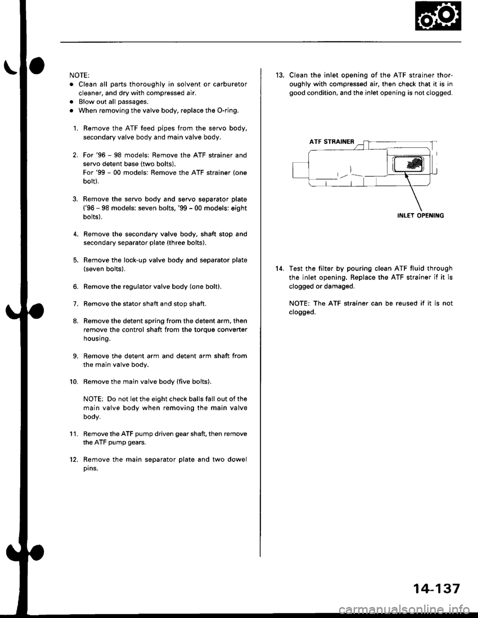
NOTE;
. Clean all parts thoroughly in solvent or carburetor
cleaner, and dry with compressed air.
. Blow out all passages.
. When removing the valve body, replace the O-ring.
l, Remove the ATF feed pipes from the servo body,
secondary valve body and main valve body.
For'96 - 98 models: Remove the ATF strainer and
servo detent base (two bolts).
For'99 - 00 models: Remove the ATF strainer (one
bolt).
Remove the servo body and servo separator plate
{'96 - 98 models: seven bolts,'99 - 00 models: eight
bolts).
Remove the secondary valve body, shaft stop and
secondary separator plate (three bolts).
Remove the lock-up valve body and separator plate
{seven bolts).
Remove the regulator valve body (one boltl.
Remove the stator shaft and stop shaft.
Remove the detent spring from the detent arm. then
remove the control shaft from the to.que converter
housing.
Remove the detent arm and detent arm shaft from
the main valve body.
Remove the main valve body (five bolts).
NOTE: Do not let the eight check balls fall outofthe
main valve body when removing the main valve
body.
Remove the ATF pump driven gear shaft, then remove
the ATF pump gears.
Remove the main separator plate and two dowel
pins.
7.
't'1.
10.
12.
14.
13. CIean the inlet opening of the ATF strainer thor-
oughly with compressed air. then check that it is in
good condition, and the inlet opening is not clogged.
INLET OPENING
Test the filter by pouring clean ATF fluid through
the inlet opening. Beplace the ATF strainer if it is
clogged or damaged.
NOTE: The ATF str8iner can be reused if it is not
clogged.
14-137
Page 816 of 2189
Valve Caps
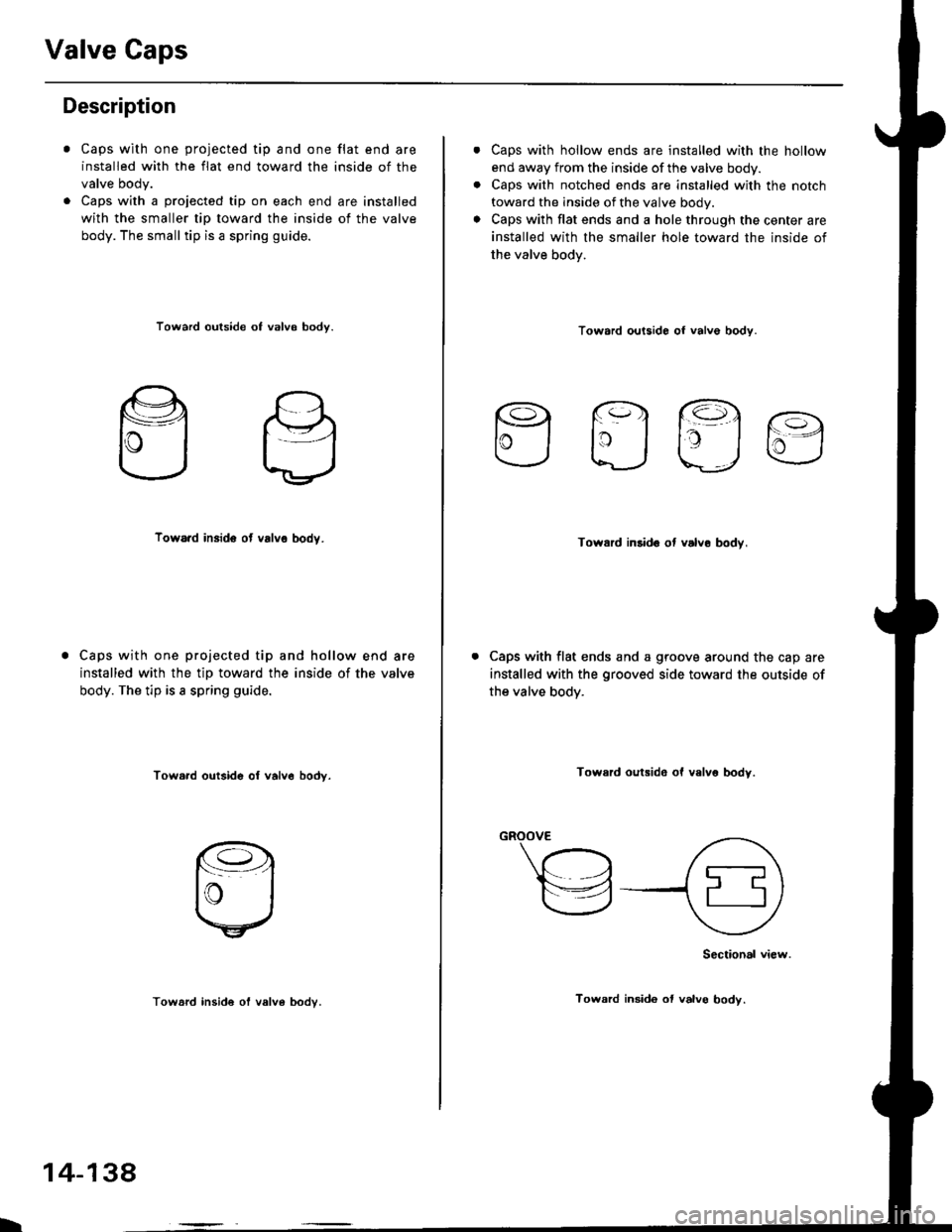
Description
Caps with one projected tip and one flat end are
installed with the flat end toward the inside of the
valve body.
Caps with a projected tip on each end are installed
with the smaller tip toward the inside of the valve
body. The small tip is a spring guide.
Toward outside of valvo body.
Toward insido ot valvo body.
Caps with one projected tip and hollow end are
installed with the tip toward the inside of the valve
body. The tip is a spring guide.
Towa.d outside o, valv6 bodv.
I
14-138
Toward insid€ of valv6 bodv.
Caps with hollow ends are installed with the hollow
end away from the inside ofthe valve body.
Caps with notched ends are installed with the notch
toward the inside of the valve body.
Caps with flat ends and a hole through the center are
installed with the smaller hole toward the inside of
the valve bodv.
Toward outsido of valve bodv.
Efla
Toward inlido ot valve bodv,
Caps with flat ends and a groove around the cap are
installed with the grooved side toward the outside of
the valve body.
Toward oulsido of valv6 body.
"-\"h
,A
\za9
Sectional view.
Toward insido ol valvo body.
Page 817 of 2189
Valve Body
2.
Repair
NOTE: This repair is only necessary if one or more of
the valves in a valve body do not slide smoothly in their
bores. You may use this procedure to free the valves in
the valve bodies.
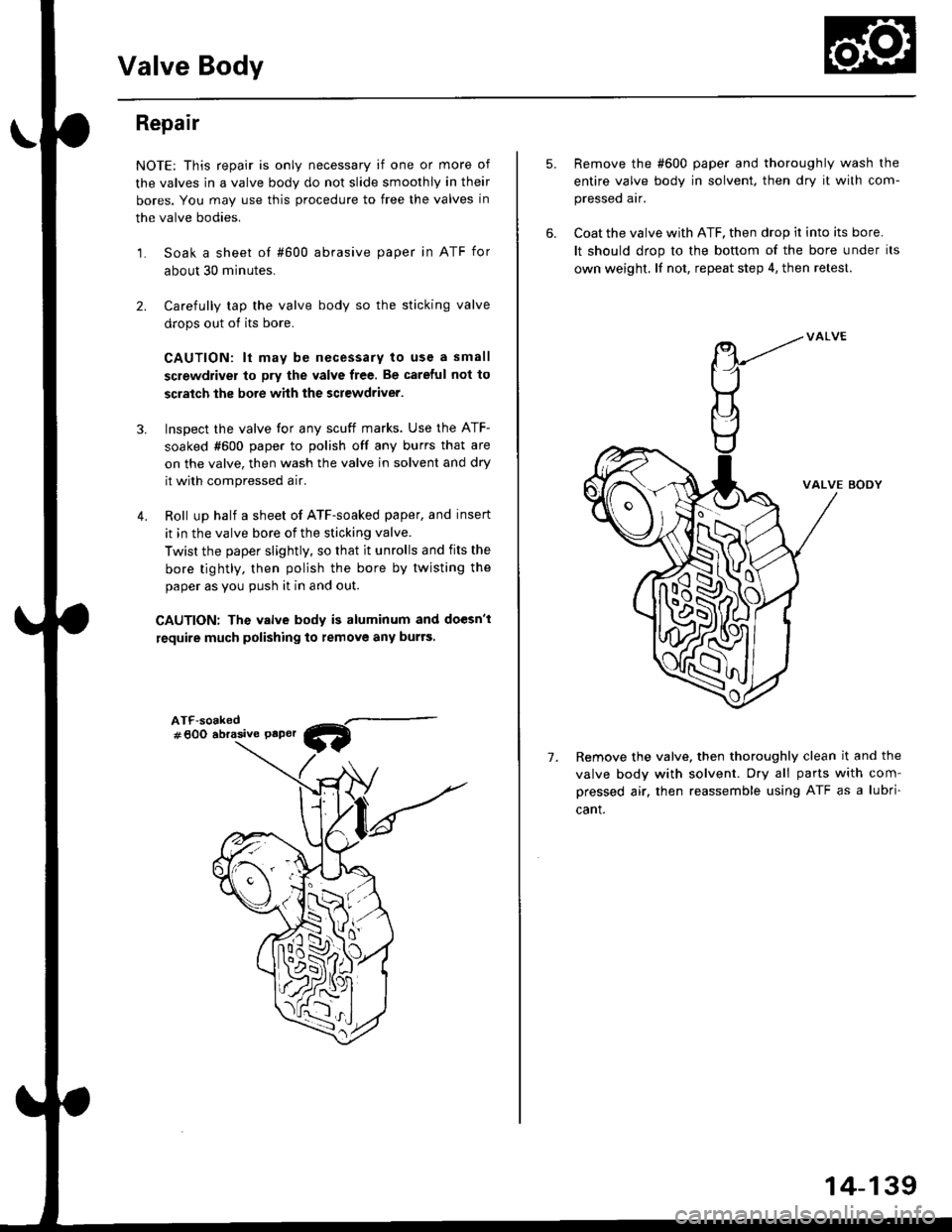
1. Soak a sheet of #600 abrasive paper in ATF for
about 30 minutes.
Carefully tap the valve body so the sticking valve
drops out of its bore.
CAUTION: lt may b€ necessary to use a small
screwdriver to pry the valve free. Be careful not to
scratch the bore whh the screwdriver.
Inspect the valve for any scuff marks. Use the ATF-
soaked #600 paper to polish off any burrs that are
on the valve, then wash the valve in solvent and dry
it with compressed a ir.
Roll up half a sheet of ATF-soaked paper, and insert
it in the valve bore of the sticking valve.
Twist the paper slightly, so that it unrolls and fits the
bore tightly, then polish the bore by twisting the
paper as you push it in and out.
CAUTION: The valve body is aluminum and doesn't
require much polishing to remove any burrs,
3.
4.
ATF-soaked#600 abrasive Paper
5.
7.
Remove the #600 paper and thoroughly wash the
entire valve body in solvent. then dry it with com-
pressed air.
Coat the valve with ATF, then drop ir into its bore.
It should drop to the bonom of the bore under its
own weight. lf not, repeat step 4, then retest.
VALVE BODY
Remove the valve. then thoroughly clean it and the
valve body with solvent. Dry all parts with com-
pressed air. then reassemble using ATF as a lubri
cant.
W
-M
14-139