ecm HONDA CIVIC 1999 6.G Workshop Manual
[x] Cancel search | Manufacturer: HONDA, Model Year: 1999, Model line: CIVIC, Model: HONDA CIVIC 1999 6.GPages: 2189, PDF Size: 69.39 MB
Page 1496 of 2189
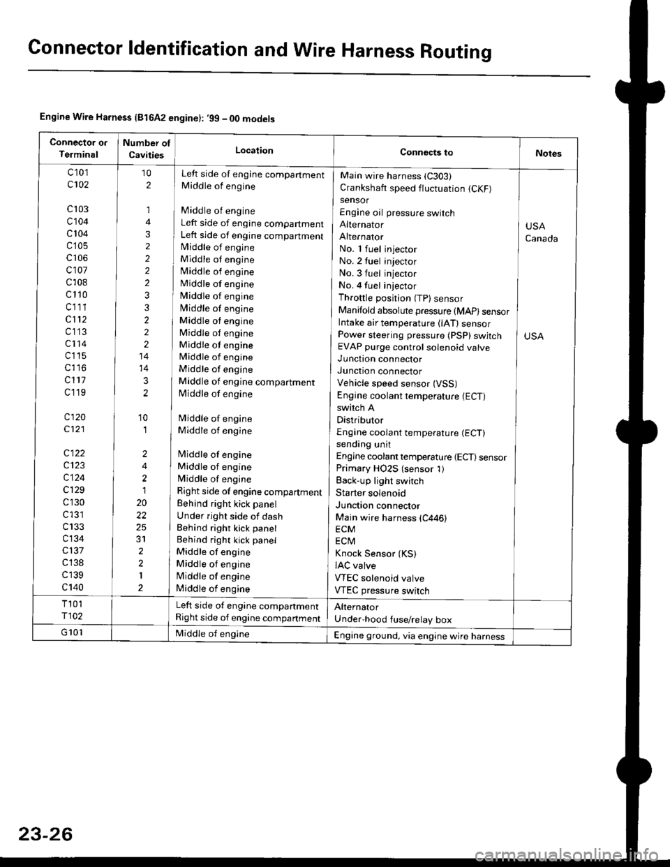
Connector ldentification and WireHarness Routing
Engine Wire Harness {81642 engine}: .99 - 00 models
c 101
c102
cl03
c104
c 104
c'105
c106
cl01
c108
c110
cl11
cl12
c1'13
c114
c115
c117
cl19
c120
c121
c122
c123
c124
c129
c130
c l31
c133
c134
c137
c 138
c139
c140
Left side of engine companment
Middle of engine
Middle of engine
Left side of engine compartment
Left side of engine compartmentlvliddle of engine
Middle ot engine
Middle of engine
Middle of engine
Middle of engine
Middle of engine
Middle ot engine
Middle of engine
Middle of engine
Middle of engine
Middle of engine
Middle of engine compartment
Middle of engine
Middle of engine
Middle of engine
lMiddle of engine
Middle of engine
Middle of engine
Right side of engine compartment
Behind right kick panel
Under right side of dash
Behind right kick panel
Behind right kick panel
Middle of engine
Middle ot engine
lMiddle of engine
Middle of engine
10
2
,]
4
3
2
2
2
2
3
3
2
2
2
14
14
3
2
'10
'I
2
4
2
1
20
22
25
31
2
2
I
Main wire harness (C303)
Crankshaft speed fluctuation (CKF)
sensor
Engine oil pressure switch
Alternator
Alternator
No. 1 fuel injector
No. 2 tuel injector
No. 3 fuel injector
No. 4 fuel injector
Throttle position (TP) sensor
Manifold absolute pressure (MAP) sensorIntake air temperature (lAT) sensorPower steering pressure (PSP) swjtchEVAP purge control solenoid valve
Junction connector
Junction connector
Vehicle speed sensor (VSS)
Engine coolant temperature (ECT)
switch A
Distributor
Engine coolant temperature (ECT)
sending unit
Engine coolant temperature {ECT) sensorPrimary HO2S (sensor 1)
Back-up light switch
Starter solenoid
Junction connector
Main wire harness (C446)
ECM
ECtvl
Knock Sensor {KS)IAC valve
VTEC solenoid valve
VTEC pressure switch
USA
Canada
Left side of engine companment
Right side of engine compartment
Engine ground, via engine wire harness
Page 1508 of 2189
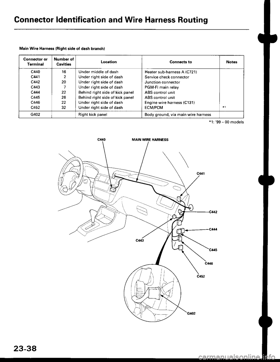
Gonnector ldentification and Wire Harness Routing
Msin Wire Harness (Right side oI dash branch)
Connector or
Terminal
Number of
CavitiesLocationConnects toNotes
c440
c441
c442
c443
c4M
c445
c446
c452
16
2
20
7
22
22
Under middle of dash
Under right side of dash
Under right side of dash
Under right side of dash
Behind right side of kick panel
Behind right side of kick panel
Under right side of dash
Under right side of dash
Heater sub-harness A (C721)
Service check connector
Junction connector
PGM-Fl main relay
ABS control unit
ABS control unit
Engine wire harness (C131)
ECM/PCM
G402Right kick panelBody ground, via main wire harness
*'l: '99 - 00 models
23-38
Page 1533 of 2189
(l'-
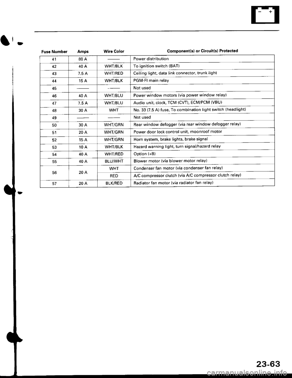
Fuse NumberAmpswire ColorComponent(s) or Circuitlsl Protect€d
4180APower distribution
4240AWHT/BLKTo ignition switch (BAT)
437.5 AWHT/REDCeiling light, data link connector, trunk light
4415 AWHT/BLKPGM-Fl main relay
Not used
4640AWHT/BLUPower window motors (via power window relay)
477.5 AWHT/BLUAudio unit, clock, TCM (CVT), ECM/PCM (VBU)
4830AWHTNo.33 (7.5 A) fuse, To combination light switch (headlight)
49Not used
5030AWHT/GRNRear window defogger (via rear window defogger relay)
cl20AWHT/GRNPower door lock control unit, moonroof motor
15 AWHT/GRNHorn system, brake lights, brake signal
10 AWHT/BLKHazard warning light, turn signal/hazard rclay
54404WHT/REDOption {+B)
5540ABLU,A/VHTBlower motor (via blower motor relay)
204WHTCondenser fan motor (via condenser fan relay)
REDl'lc compressor clutch (via IVC compressor clutch relay)
204BLVBEDRadiator fan motor (via radiator fan relay)
23-6
Page 1535 of 2189
lr-
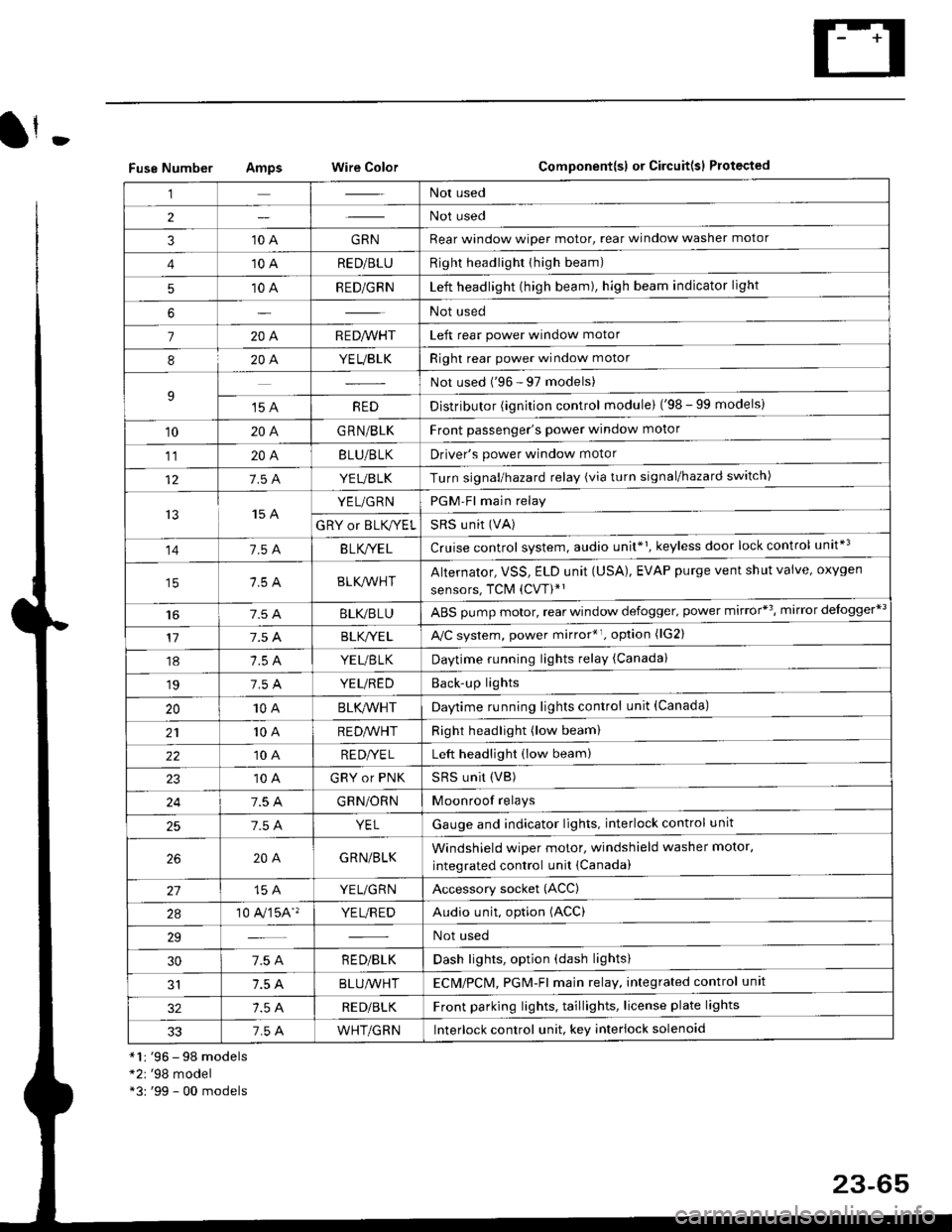
Fuse NumberAmpswire ColorComponent{sl or Circuit(sl Protected
*1r '96 - 98 models*2r '98 model*3: '99 - 00 models
,lNot used
2Not used
310 AGRNRear window wioer motor, rear window washer motor
410 ARED/BLURight headlighr thigh beam)
510 ARED/GRNLeft headlight (high beam), high beam indicator light
6Not used
7204R E D/VVHTLeft rear power window motor
820A.YEUBLKRight rear power window motor
9Not used ('96 - 97 models)
't5 AREDDistributor (ignition control module) ('98 - 99 models)
10204G RN/BLKFront passenger's power window motor
1120ABLU/BLKDriver's power window motor
127.5 AYEUBLKTurn signal/hazard relay (via turn signal/hazard switch)
t515 AYEL/GRNPGM-Fl main relay
GRY or BLK,^/ELSRS u nit (VA)
141.54B LK/YE LCruise control system, audio unit*1, keyless door lock control unit*3
BLK/lr'r'HTAlternator, VSS, ELD unit (USA), EVAP purge vent shut valve, oxygen
sensors, TCM (CVT)*'
t6BLI(,/BLUABS pump motor, rear window defogger. power mirror*3, mirror delogger*3
177.5 ABLK,/YE LA,/C system, power mirror*r. option (lG2)
18YEUBTKDaytime running lights relay (Canada)
197.5 AYEUREDBack'up lights
2010ABLK/VVHTDaytime running lights control unit (Canada)
2110 AREDA/VHTRight headlight (low beam)
2210 ARE DI/E LLeft headlight (low beam)
10 AGRY or PNKSRS UNit (VB)
247.5 AGRN/ORNMoonroof relays
257.5 AYELGauge and indicator lights. interlock control unit
204GRN/BLKWindshield wiper motor, windshield washer motor,
integrated control unit {Canada)
15 AYEL/GRNAccessory socket (ACC)
2a10 A,/'�]5A''YE L/R EDAudio unit, option (ACC)
29Not used
307.5 AR ED/BLKDash lights, option (dash lights)
1.5 ABLUA/VHTECM/PCl\4, PGM-Fl majn relay, integrated control unit
RED/BLKFront parking lights, taillights, license plate lights
337.5 AWHT/GRNlnterlock control unit. key interlock solenoid
23-65
Page 1537 of 2189
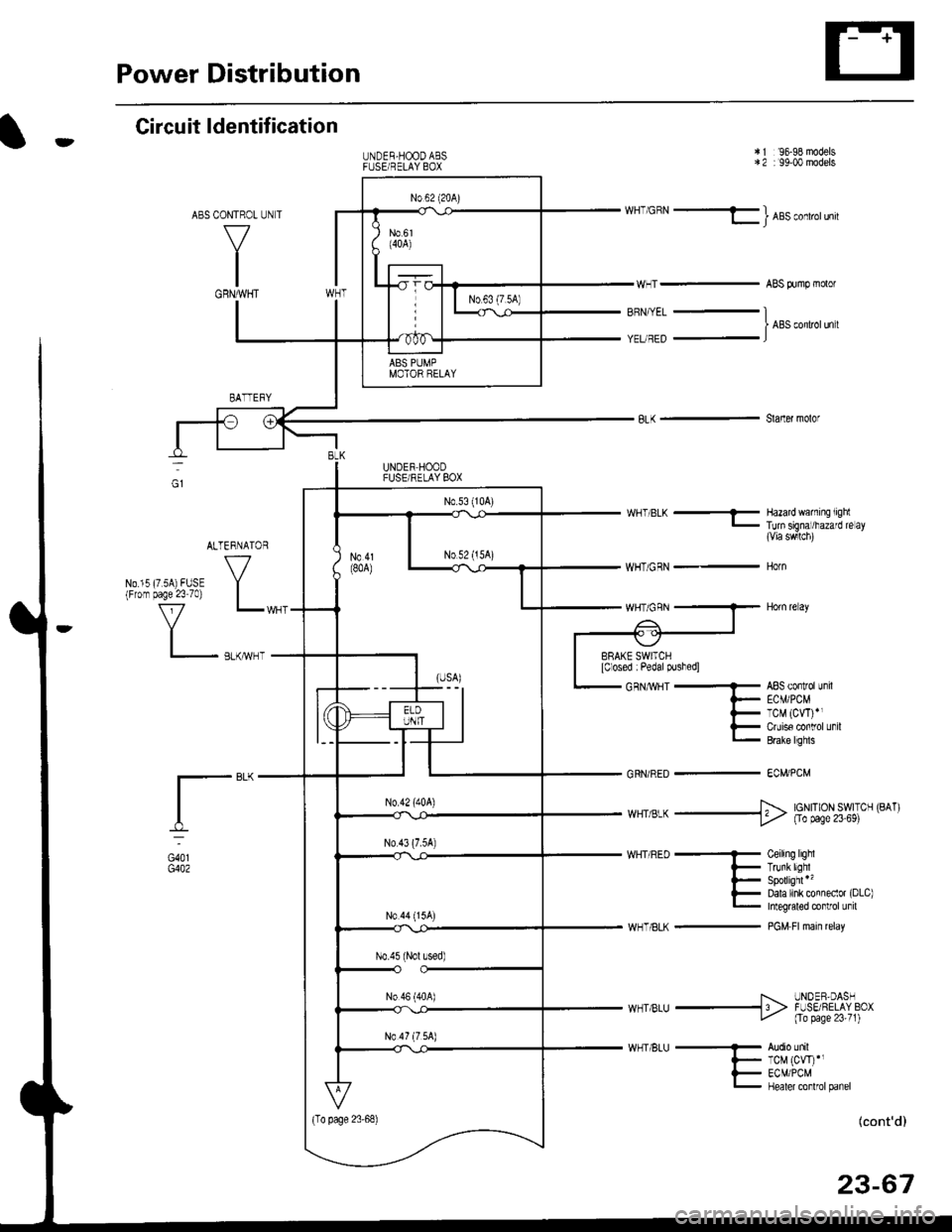
Power Distribution
tCircuit ldentification
CONTROL
V
IGRNMHT
UNDER-HOODABSFUSEi RELAY BOX
'96-98 models: 99-00 models
WHT'GBN - l ABs conlrorun
ABS Aimp molor
*2
BRN,ryEL
YEUREDI ABS conltolun t
Slaner molor
WHT/BLK ..........-
WHT/GRN _-
WHTiGBN
GRN/RED -
Hazard waming liglTun signal/hazard re ay{Via swlch)
HOTN
HOn re ay
ABs controllnilECMi PCMTCM (CW)rlCruise conlrol unilErake lrghls
EC}?VPCM
I-"-
G401G402
I... UNOER.DASHw_T BLU -13 > F-SE ?ELAY BCxt- Fa Nge23:t)
Audio unilTCM (CW)',ECM/PCMHealer conlrolpanel
(cont'd)
23-67
UNDER HOODFUSEi RELAY BOX
ALTERNATOR
VNo 15 (7 sA) FUSE Y(From page 23 70) |
f7 r_1
I_ .,.-.,
*,,,,,* _$ lg|[|];gil.' ('^')
WHT/8LK -
Ceiling lighlTrunkllghrSpollighl *'�
Dala link connecor (DLc)Integraled control unil
PGM Fl main relay
Page 1540 of 2189
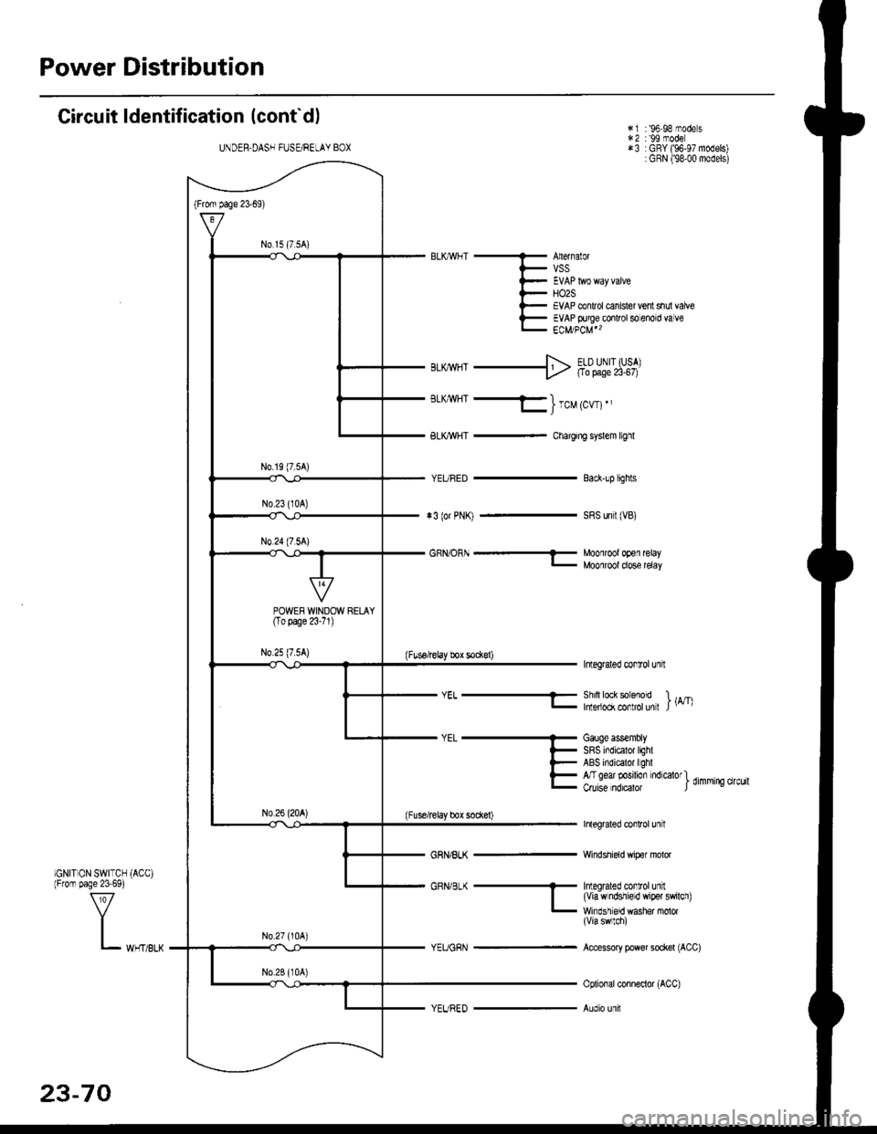
Power Distribution
Circuit ldentification (cont'd)
IGN|T 0N SWTTCH (ACo)lFrom page 23-69)
*3 (or PNn -
Anernal0rVSS
HO2SEVAP conlrol canister vent shr,,l vafoeEVAP Flrge conrol so enord valveECM/PCM"
Back-!p lighls
SRS unri (VB)
i.1 :'96,98 modesr.2 : 99 mode*3 :GRY ('96-97 models):GRN (98'00 models)
sLrwHT+ Ft"t:itJY;i
BLI{WHT -}rcutcwt.,
BLKr'r{HT - Chargir! syslem trghl
InteEalei conLol unft
Shin lock soenod I r!/r\lnleiock mnlrol un I J '- '
Galge ass€mblySRS indicalor lighlABS indicrtor lghlA/Igear posilion nd€lorl d,mmino qrcu,luru6e notcaoa ) -
Inlegraled conlrcl un t
Windshield wiper molor
GRN,B-< ........- ImeEaleo cortolull| (viawndshieLd wi9el swllci)- wrrdsi erd washer .nolor(Via swrn)
Accessory power sockel (ACC)
oplioial conneclor (Acc)
Audio unil
UNDEF.DASH FUSE/REtAY BOX
No 1s (7 sA)
POWERWINDOW RELAY(To page 23-71 )
N0.25 (7.5A)
GBN/OF -- Moolroolopel relay- MOOlrOOldOSe relav
(Fusoirelay box sockel)
YEL-
(Fuse/relay box socl€l)
Y_ *,n,,*
23-70
Page 1546 of 2189
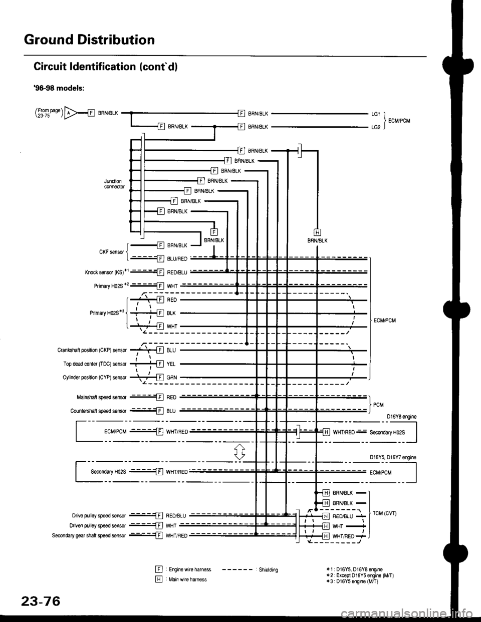
Ground Distribution
Circuit ldentification (conf dl
'9&98 models:
(t[oileas6)>{ BRN/BLKLGl II EcM/PcMlcz J
[..........{ BFNaLKCKF sensor jL .-!l 8LU/FED
Knoct s€rlsor (KS)r' ::{ REDtsLU
PimaryH02S*?- wHT
Matnsnafi g]€eo sdnsoa -'1 t I HEL)
Counlersiall speed sensor --={Fl BIU
Ecr#PcM ----Tal WHT/BED
Dive trjiley speed seftsor -1ll FED,ALU
0 ven pulley speed sensor .-lJ WHT
Seconftry gear shalt speed sansor .-!.1 WHT/RED
44:lil
ECIVPCM
)*"Dl6YBengine
Dl6Y5, D16Y7 sngine
vtl
8BM/BLK - IBBi1/BLK _ I^l^1ll'. I rcu rcwr
**' -i IWHT/RED + ]
El , Engln" *lr" h"rn""" - - - - - - : Shietorns
E : Main *re harness
23-76
* 1 :D16Y5,016Y8 engino* 2 : Excepl Dl 6Y5 engine (i//T)+3: D16Y5 engine (Mfi)
Page 1565 of 2189
-Starter Test
NOTE; The air temoerature must be between 59 and
100'F (15 and 38"C) before testing.
Recommended Procedure:
. Use a staner system tester.
. Connect and operate the equipment in accordance
with the manufacturer's instructions.
. Test and troubleshoot as described,
Alternate Procedurg:
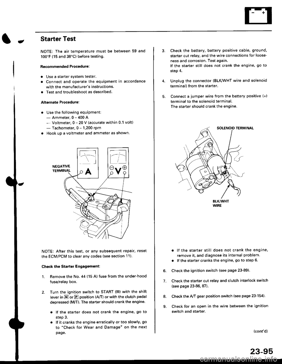
. Use the following equipment:- Ammeter, 0 - 400 A
- Voltmeter, 0 - 20 V (accurate within 0.1 volt)
- Tachometer, 0 - 1,200 rpm
. Hook up a voltmeter and ammeter as shown.
NEGATIVETERMINAL
NOTE: After this test, or any subsequent repair. reset
the ECM/PCM to clear any codes (see section l1)
Check the Start€r Engagemont:
1. Remove the No. 44 (15 A) fuse from the under-hood
fuse/relay box,
2. Turn the ignition switch to START (llll with the shift
lever in E or E position (rVT) or with the clutch pedal
depressed {M/T). The starter should crank the engine.
. lf the starter does not crank the engine, go to
step 3.
. lf itcranksthe engineerraticallyortooslowly, go
to "Check for Wear and Damage" on the next
page.
Check the battery. battery positive cable, ground,
starter cut relay, and the wire connections for loose-
ness and corrosion, Test again.
lf the starter still does not crank the engine, go to
step 4,
Unplug the connector (BLK,/WHT wire and solenoid
terminal) from the starter,
Connect a jumper wire from the battery positive (+)
terminal to the solenoid terminal.
The starter should crank the engine.
. lf the starter still does not crank the engine,
remove it, and diagnose its internal problem
. lf the startercranksthe engine, goto step 6.
Check the ignition switch (see page 23-891.
Check the starter cut relay and clutch interlock switch
(see page 23-86,87).
Check the A/f gear position switch (see page 23-154).
Check for an open in the wire between the ignition
switch and starter.
7.
(cont'd)
23-95
9.
Page 1579 of 2189
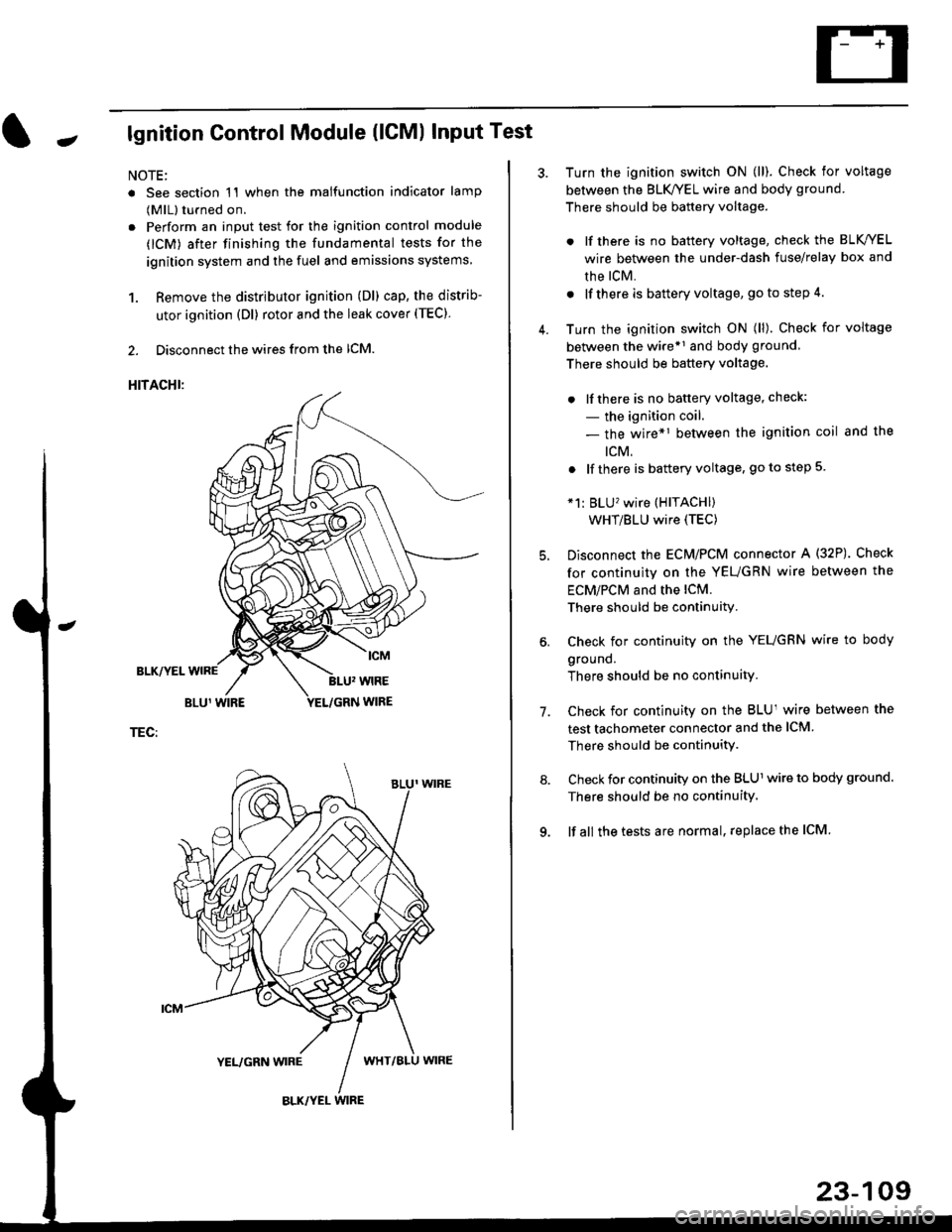
Jlgnition Control Module (lCMl Input Test
NOTE:
. See section 1'l when the malfunction indicator lamp
(MlL) turned on.
. Perform an input test for the ignition control module
(lCM) after finishing the fundamental tests for the
ignition system and the fuel and emissions systems
1. Remove the distributor ignition (Dl) cap, the distrib-
utor ignition (Dl) rotor and the leak cover (TEC).
2. Disconnect the wires from the lCM.
HITACHI:
BLK/YEL
TEC:
Turn the ignition switch ON (ll). Check for voltage
between the BLK/YEL wire and body ground.
There should be battery voltage.
. lf there is no battery voltage, check the BLK/YEL
wire between the under-dash fuse/relay box and
rhe lcM.
. lf there is battery voltage, go to step 4.
Turn the ignition switch ON (ll). Check for voltage
between the wire*r and body ground
There should be battery voltage.
. lfthere is no battery voltage, check:
- the ignition coil.
- the wire*1 between the ignition coil and the
tcM.
. lf there is battery voltage, go to step 5
*1: BLU'�wire (HITACHI)
WHT/BLU wire (TEC)
Disconnect the EcM/PCM connector A (32P). Check
for continuity on the YEUGRN wire between the
ECM/PCM and the lCM.
There should be continuity.
Check for continuity on the YEUGRN wire to body
ground.
There should be no continuity.
Check for continuity on the BLUl wire between the
test tachometer connector and the ICM
There should be continuitY.
Check for continuity on the BLUl wire to body ground.
There should be no continuity.
lf all the tests are normal, replace the ICM
7.
23-109
Page 1583 of 2189
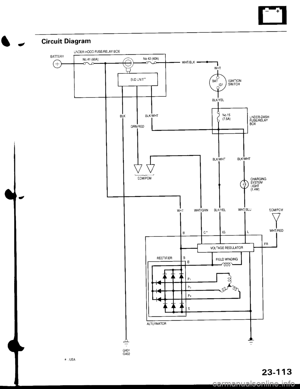
Circuit Diagram
IJNDER HOOD FUSEi RELAY BOX
-
BATTERY
LGNlTIONSWITCH
I
,'-F\I BAT I Gl /
\l_/
I
GRN/RED
I
N0.41 (80A) ,-a No 42 (40A)
ECM/PCM
f7
IWHT/RED
CHARGINGSYSTEMLIGHTI
TWHTi BLU
1323-1
ALTERNATOF