ecm HONDA CIVIC 1999 6.G Workshop Manual
[x] Cancel search | Manufacturer: HONDA, Model Year: 1999, Model line: CIVIC, Model: HONDA CIVIC 1999 6.GPages: 2189, PDF Size: 69.39 MB
Page 1928 of 2189
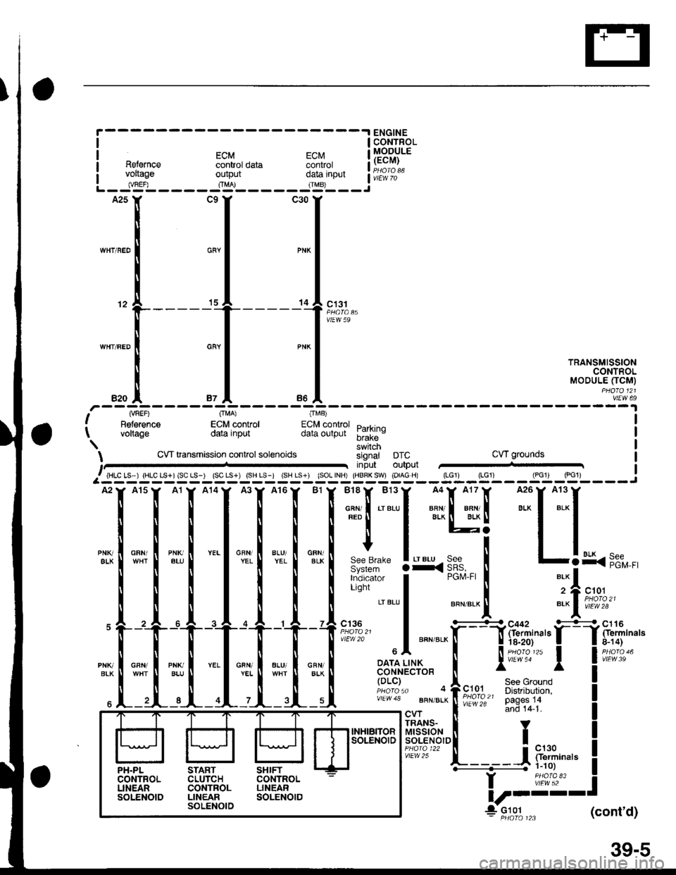
aI
I coNrRoL
EcM EcM lllg?.Y.ERelernce control data control I H;,."voftase output ff.'nour a;i:;Y"*- lug'L - - - - JS- - - - - J't3'- - - iA25Y CgY C30Y
lL
I 1=,
-"'"'"1 ""1 "-l
rRANsM,ss,oN
,r, ,[ ", I ". I
"oou".-o'"[3fl!
NnEF) O[,!A) OMB)Beference ECM control ECM control D..r.i.^vollage data input data output ;;ii; vI
t
swrtch
CVT transmrssion conlrol solenoids signal DTC CVT grounds
j input outputlPcrr /pcl).t HLC LS I iHLC LS+l {SC LS-) tSC LS-) (SH Ls-i ISH LS-l ISOL INH' THBRK SWt {O'AG Hr {LGli {LGl) lPclr tpclj :
{*n*
:".,1 :"::.1 i.lnu+
',sk,-[lr*:[l*':t'
*?:?' """",.0-fr;rt.o,1^,, *'ig"#"t I""-t cw i
-"' iiio lr.'t l
lsel$tfis'! I !
izf-"{}Y
f,====i iiu:'" !
I ii,l;?:' i
lt r---L
4 9::1",- (cont'd)
39-s
PH.PL START SHIFTCONTFOL CLUTCH COITTROLLINEAR CONTROL LINEARSOLENOID LINEAR SOLENOIDSOL:NOID
Page 1954 of 2189
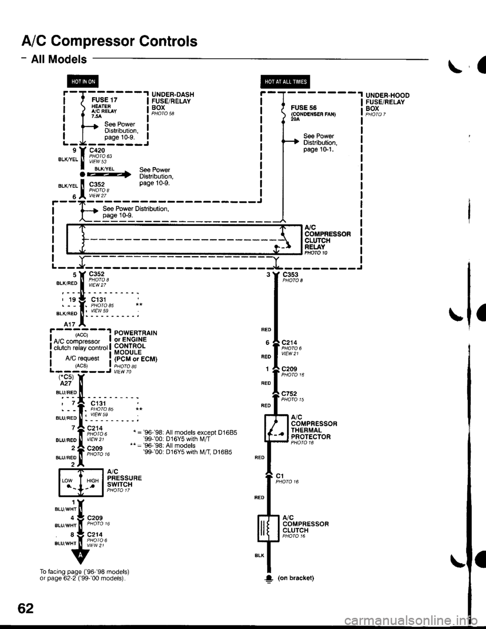
A/C Compressor Controls
- AllModels
cc5)M7
BLU/RED
?
\a
@
&cCOMPRESSORCLUTCHRELAYPHOfO 10
a
! ,acc, : POWERTRATN! arn.^-^,o..^, I or ENGINE
! ii i"i-iiii"v i.,ii.r | fi 3$18.
I A/C request ! (pCM or ECM)I (ACSJ a pHOrO a6L------J vtEw 70
REO
BEO
1
RED
BLU/FEO
2
BLU/FEO
ct31
:"1'!i'------;
Fi:rz, a ='e6-'s8: A|| moders except D1685vtEw 21 '99100: D16Y5 with l\illT'* = 96-'98: All models
ir'iio ," 99. 00: Dt6y5 wth t\4/t Dl6Bb
atcPRESSUREswtTcH
c752
c1
".,n""t 1(
".r-".rf, "tA% "
"."-:,fi tfr,]4.
v
To facing page ('96''98 models)or page 62'2 ( 99-'00 models).
-Yl
-t---------Jc353
c2'14
vtEW21
c209
A,/CCOMPRESSORCLUTCH
COMPRESSORTHERMALPROTECTOR
UNDER-HOODFUSE/RELAYBOXf-T-*-'.T'---l H53.',EPA?' i-l-------
i iflH* !F,?r",, i f6F"'.i:.",",
| tsBi":J;"#il ! a T| | oaoe 1o-9. ! I I See PowerL_J1_j:_-_j ! H Distriburion.e Y c42o i I
pase 1o-1.
***
f ifi"l'
^ see power ! |
62
!(on bracket)
Page 1957 of 2189
- How the Circuit Works
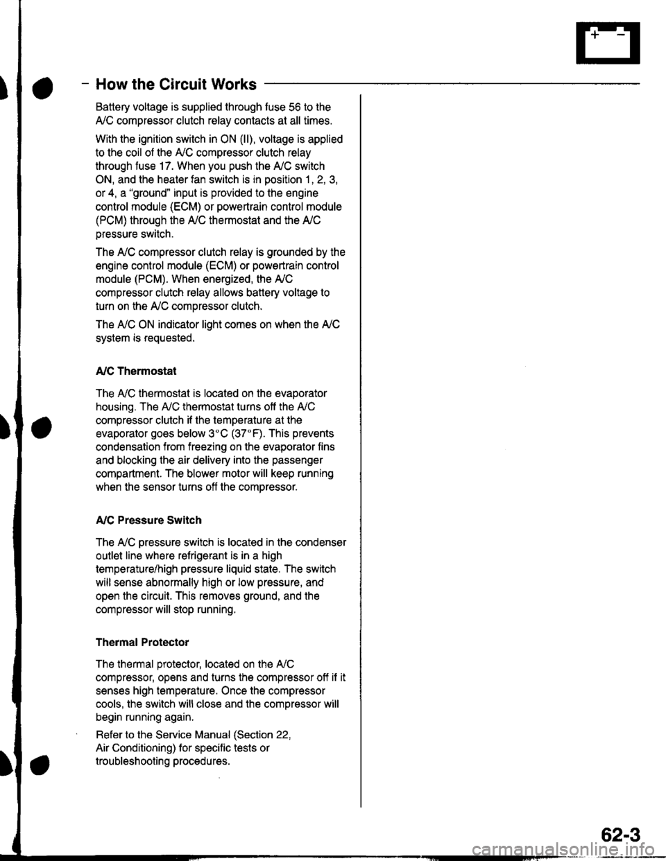
Battery voltage is supplied through tuse 56 to the
A,/C compressor clutch r€lay contacts at all times.
With the ignition switch in ON (ll), vollage is applied
to the coil of the A,/C compressor clutch relay
through fuse 17. When you push the A,/C switch
ON, and the heater fan switch is in position | , 2, 3,
or 4, a "ground" input is provided to the engine
control module (ECM) or powertrain control module
(PCM) through the l'lC thermostat and the l'lC
pressure switch.
The A,/C compressor clutch relay is grounded by the
engine control module (ECM) or powertrain control
module (PCM). When energized, the A'lC
compressor clutch relay allows battery voltage to
turn on the A,/C comDressor clutch.
The A,/C ON indicator light comes on when the A,/C
system is requested.
A,/C Thermostat
The A'lC thermostat is located on the evaoorator
housing. The A,/C thermostat turns off the A,/C
compressor clutch if the temperature at the
evaporator goes below 3'C (37'F). This prevents
condensation from freezing on the evaporator fins
and blocking the air delivery into the passenger
compartment. The blower motor will keep running
when the sensor turns off the comDressor.
A,/C Pressure Switch
The fuC oressure switch is located in the condenser
outlet line where refrigerant is in a high
temperature/high pressure liquid state. The switch
will sense abnormally high or low pressure, and
open the circuit. This removes ground, and the
compressor will stop running.
Thermal Protectot
The thermal protector, located on the A,/C
compressor, opens and turns the compressor off if it
senses high temperature. Once the compressor
cools, the switch will close and the compressor will
begin running again.
Refer to the Service Manual (Section 22,
Air Conditioning) for specific tests or
troubleshooting procedures.
62-3
Page 1958 of 2189
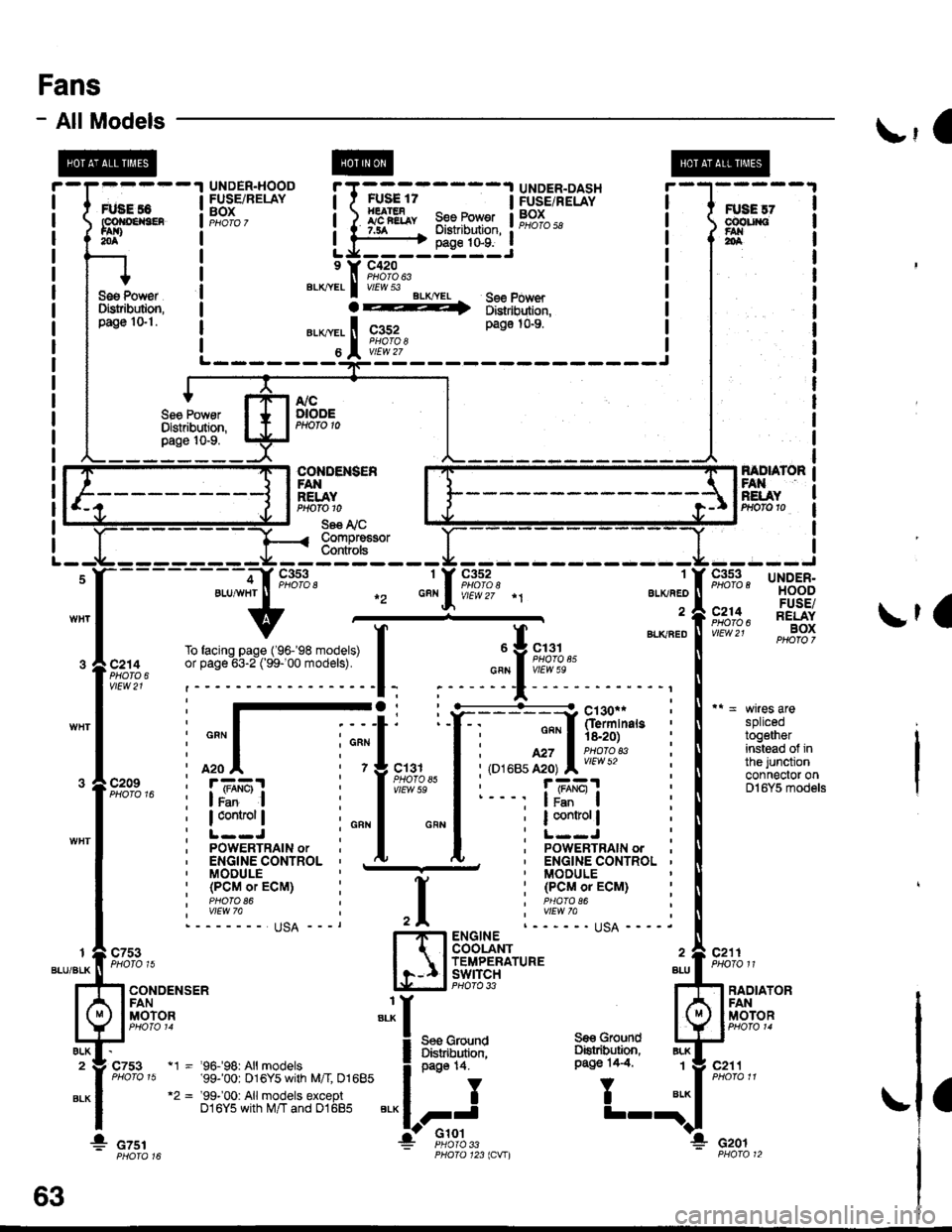
Fans
- AllModels\,1 |
splicedtogetherinstead of inthe junctionconnector onDl6Y5 models
c211PHOTO 11
FANRELAYPrtofo 10
Se€ I'i CCompre€sorCont ols
1
ALKAED
a
c352
f BLKaEou Y 9,;%,.cFN I vIEw 5e
;
"'
T
";::-:.."-!
Y:. ---::Y h!ii'in"," :
I : ""'I 'is.2o) :
I i,o''ur,ff;, l;l:'l?'* i
I r- - -, |JBEI :
I ; I control | ;
I :L--J :I ' PoWERTRAIN ordu. ' ENGINE CONTROL '' MODULE
: (PCMoTECM) :I PHAfO 86I wEw 7allqA ----.ENGINECOOLANTTEMPERATUREswtrcH BLLPHO|O 33 ?
Ses GrolndDiskibution,oaqe 14.
,I
H
:I
i:
"'*
1_l
c7531
BLU/BLK
ALK2
BLK
RADIATORFANMOTORI
BLK
BLK1
ELK
c753
CONDENSERFANMOTOR
a
* czsr
page 14.
II
FJ'Glot
c211
Gro!nd
T
Se€ GroundOstribution,Pago 14.4"t1 - '96.f98: All models'99-'00: 016Y5 with M/I 01685"2 = '99-'00: Allmodels exceptD16Y5 with M/T and 01685
cof{oENs€R
* czor33123lCVIl
63
Page 1961 of 2189
- How the Circuit Works
Radiator Fan
Voltage is provided at all times to the radiator fan
relay (contacts) through fuse 57. With the ignition
swilch in ON (ll), voltage is provided to the coil of
the relay through luse 17.
The radiator tan relay can be grounded through
either the engine coolant temperature switch or the
engine control module (ECM) or powertrain control
module (PCM).
The engine coolant temperature switch grounds
the radiator fan relay (coil) when the engine
coolant temperature exceeds 199'F (83'C). The
switch opens when coolanl temperature
decreases 3'- 8'C.
Condenser Fan
Voltage is provided at all times to the condenser fan
relay (contacts) through fuse 56. With the ignition
switch in ON (ll), voltage is provided to the coil of
the relay through fuse 17. When you push the A'lC
switch and put the heater fan switch in 1, 2,3, o( 4
position, the ly'C thermostat comes on, the
condenser fan relay energizes, and the condenser
fan motor runs.
A,/C Thermostat
The A,/C thermostat is located on the evaporator
housing. The A,/C thermostat tums off the A/C
compressor clutch if the temperature at the
evaporator goes below 3'C (37'F). This prevents
condensation from freezing on the evaporator fins
and blocking the air delivery into the passenger
compartment. lf the temperature goes below 3'C
(37"F) tuming off the Ay'C thermostat, ground will be
removed from the condenser fan relay. This will
deenergize the relay and remove voltage from the
condenser fan motor causing the fan to stop running.
Reter to the Service Manual (Section 23, Eleckical)
for specific tests or troubleshooting procedures.
63-3
Page 1978 of 2189
Gauges
#'t----lllgi' i i-r-; ffiffig'i
;;;;6;;- -
ild;$ i fr{li,l[i
1 OTSTR|BUTOR r--- --.-^'l POWERTRATN
![ElF{, I i:tirtiifffii* I ":"+J (pclrrorEcM)
I
t**"**
iB,HFf ! L"T-liidfri" | ^i,i'llt"#,*'
-i]_Lryq_j""""
..-:i:I1;,,?--.,
_,1
lllftT":{"
r:l #f,t, I
! v,ersoI -!'Yv , I :"
c442
#* i ;[. r;{ 11;:#r i :;l i1[---- 11 :ff:*"'"'
'i" f+Taj i!!3lo_rrr."
SeeIndicators---{
rAcnoMErER i
I
sfr" iFSil i il"+"+w "-1itl*""
' LuqJ I F*l$"
I
i mi+',ts'fi8$,* i'' =,i!,,ii.ii:yil',g",',0,u,,
It, fri;J,, :,
-;;;U,+*r;l'd*o',
", I-7
I
I
I
I
\
\
\
I
-l
L82"'I
"'u'"'!
I s,#!,,*",
!
Nsst, oaoe so.
""1,i,
r--'! vEHtcLE! I SPEED
L__j;,#39'n.',
S€€ GroundOistribution,page 1+7.
Y
I
I
I+: c4ol
SPEEDOMElER
Page 1980 of 2189
Gauges (cont'd)
- How the Gircuit Works
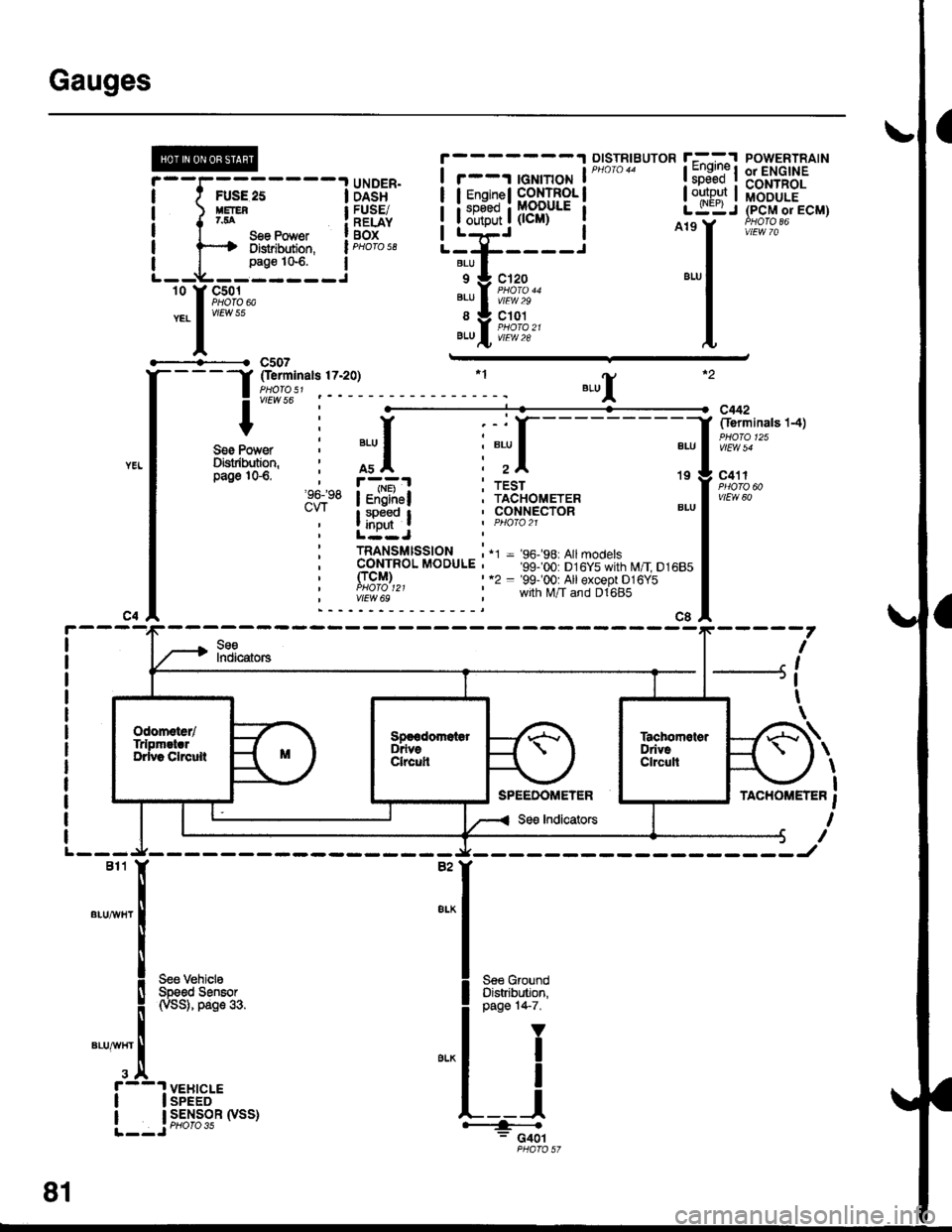
When the ignition switch is in ON (ll) or START (lll),
battery voltage is supplied through fuse 25 to the
gauges in the gauge assembly.
Speedometer and Odometer
The odometer and soeedometer drive circuits
receive pulses from the vehicle speed sensor
(VSS). The pulse rate increases as the car
accelerates. The frequency and duration of these
input pulses are measured and displayed by the
speedometer, odometer and tripmeter.
Tachometer
The tachometer drive circuit receives pulses from
the ignition control module (lCM) in the distributor
assembly or the ECM/PCM. The solid-state
lachometer then displays these pulses as engine
speed. For each 200 pulses per minute from the
ignition control modul€ (lCM) or the ECM/PCM, the
tachometer displays 100 RPM.
Engine Coolant Temperature Gauge
The engine coolant temperature gauge has two
intersecting coils wound around a permanent
magnet rotor. Voltage applied to the coils, through
fuse 25, generates a magnetic lield. The magnetic
field, controlled by the coolant temperature sending
unit, causes the rotor to rotate and the gauge
needle to move. As the resistance in the sending
unit varies, current through the gauge coils
changes. The gauge needle moves toward the coil
with the strongest magnetic field.
The 6ngine coolant temperature sending unit's
resistance varies from about 137 ohms at low
engine temperature to between 3H6 ohms at high
temperature (radiator fan running).
Refer to the Service Manual (Section 23, Electrical)
for specific tests or troubleshooting procedures.
81-2
(
Fuel Gauge (All except cX)
The fuel gauge has two intersecting coils wound
around a permanent magnet rotor. Voltage applied
to the coils, through tuse 25, generates a magnetic
field. The magnetic field, controlled by the fuel
gauge sending unit, causes the rotor to rotate and
the gauge needle to move. As the resislance in the
sending unit varies, current through the gauge coils
changes. The gauge needle moves toward the coil
with the strongest magnetic field.
The fuel gauge sending unit's resistance varies
from about 2-5 ohms at full, to about 110 ohms at
empty. When you turn the ignition switch off, the
gauge remains at the last reading until you turn the
ignition switch to ON (ll) or START (lll) again,
Refer to the Service Manual (Section 23, Electrical)
for specific tests or troubleshooting procedures.
Fuel Gauge (GX)
The fuel gauge has two intersecting coils wound
around a permanent magnet rotor. Voltage applied
to the coils, through fuse 25, generates a magnetic
field. The magnetic field, controlled by the PCM,
causes the rotor to rotate and the gauge needle to
move. The PCM calculates the gas quantity in the
fuel tank by using the fuel pressure value detected
by the tuel tank pressure sensor and the fuel
temperature value detected by the fuel tank
temperalure sensor, and outputs the signal to the
gauge assembly. The gauge needle moves toward
the coil with the strongest magnetic field.
When you turn the ignition switch off , the gauge
remains at the last reading until you turn the ignition
switch to ON (ll) or START (lll) again. When the
PCM detects a malfunction with the fuel pressure or
temperature, or detects a gas leak, the PCM
reduces the fuel meter to 0.
Refer to the Service Manual GX Supplement
(Section 11 , Fuel and Emissions) for specific tests
or troubleshooting procedures.
a
a
Page 2108 of 2189
-
Component Connector View Index (Views begin on page 202-21
Connector View
ABS Control Unit........ ......63
Audio Unit ('99-'00 models) ......74
Combination Light Switch . . . . . . . . . . . . . . . 64
Combination Wiper Switch . . . . . . . . . . . . . . 65
Cruise Control Unit.... .....43
C\TTTransmission Solenoid ............. 25
Data Link Connector (DLC) ..... 48
Daytime Runnlng Lights Control Unit ..... 66
Engine control Module (ECM) ...........70
Exhaust Gas Recirculation (EGR) Valve
and Lift Sensor (D16Y5 Mfl, D1685) . . . . 10
Gauge Assembly .............71
HazardWarnlngSwitch,,. .,,,...,,,,... 32
Heater Control Panel ('96-'98 models) .....44
Heater Control Panel ('99-'00 models) ...., 76
Heater Fan Switch ('96-'98 models) ,,,.... 11
fniector Control Module (GX) ............77
I/
202-1
Connector View
Integrated Control Unit .......,. 67
f nterfock Control Unit .... ...... 26
Keyfess Door Lock Control Unit . . . . , . . . . . 75
Mode Control Motor ... ........'17
Moonroof Close Relay .. .......13
Moonroof Open Relay ... .......15
PGM-FI Main Relay .. .......... 18
Power Door Lock Conlrol Unil ..... ...... 37
Power Mirror Switch .,... ...... 33
Power Window Master Switch .,.........36
Powertrain Control Module (PCM) .......70
Security Control Unit ..., ..,,... 58
Security Starter Cut Belay ... ...,,,....,, 12
SRS Unit ............. 51
Stereo Radio Tuner ('96-'98 models) ...... 68
Transmission Control Module CICM) .....69
Page 2133 of 2189
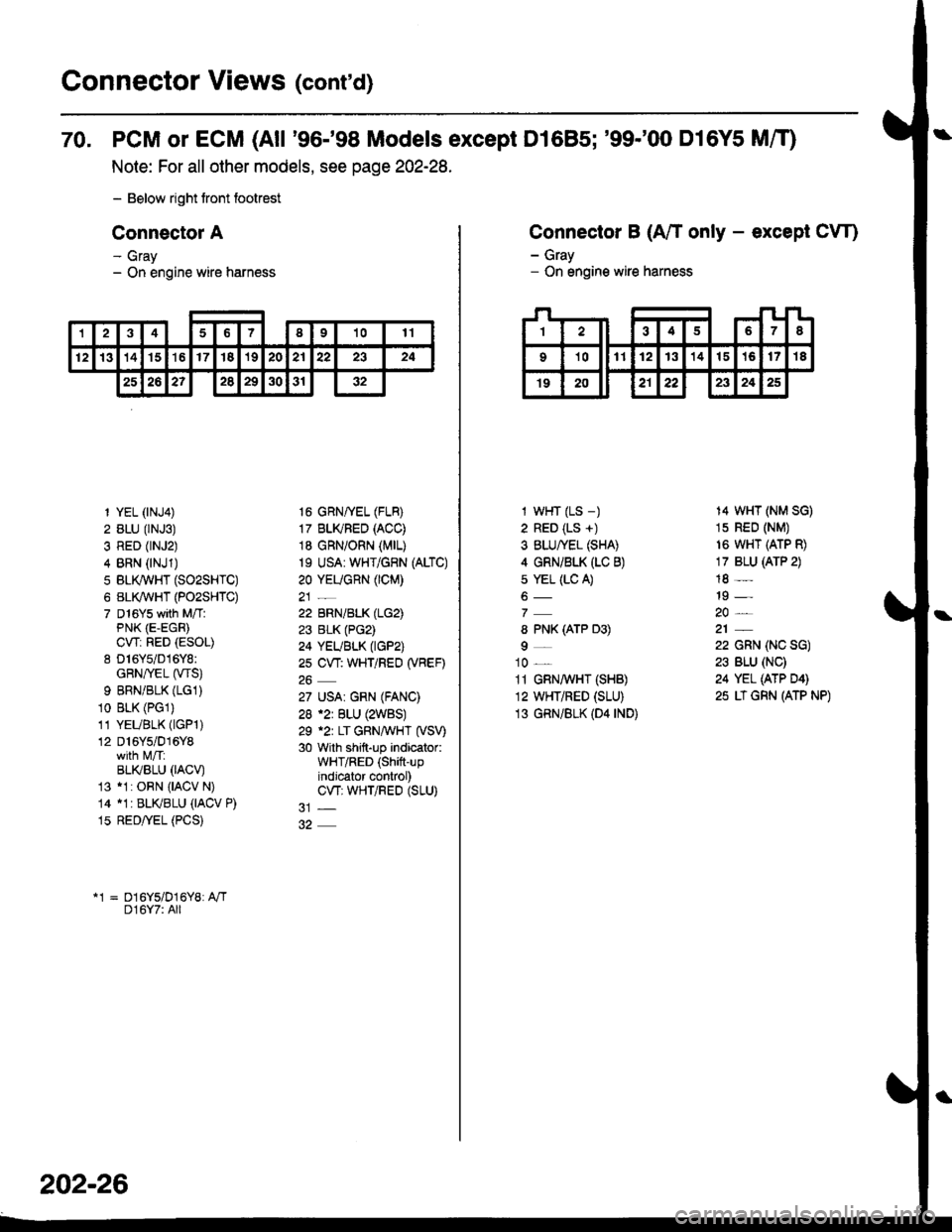
Connector Views (cont'd)
70. PCM or ECM (All '96-'98 Models except D1685; '99-'00 D16Y5 MfO
Note: For all other models, see page 202-28.
- Below right tront footrest
Connector A
- Gray- On engine wire harness
12346I91011
12131415't617'182021222324
25262?2829303'r32
1 YEL (rNJ4)
2 BLU (rNJ3)
3 RED (rNJ2)
4 BRN (NJ1)
5 BLI(WHT (SO2SHTC)
6 BL(WHT (PO2SHTC)
7 D16Ys with M/TlPNK (E-EGR)
CWi RED (ESOL)
8 D16Y5/016Y8:GRN/rEL (wS)
9 BRNiBLK (LG1)
10 BLK (PGl)
11 YEUBLK (lGPl)
12 D16Y5/016Y8
BLI(BLU 0ACV)13 11: ORN {IACV N)
14 11r BLKBLU (IACV P)
15 RED/yEL (PCS)
16 GRNffEL (FLB)
17 BLI(FED (ACC)
18 GRN/ORN (MrL)
19 USA: WHT/GRN (ALTC)
20 YEUGnN (CM)
22 BRN/BLK (LG2)
23 BLK (PG2)
24 YEUBLK (tGP2)
2s CW: WHT/REO (VBEF)
27 USA| GRN (FANC)
28 .2r BLU (2WBS)
29 .2r LT GRNAVHT (VSV)
30 with shift-up indicator:WHT/RED (Shift-upindjcator control)CW; WHTiRED (SLU)
*1 = D16Y5/D16Y8: A"/TD16Y7: All
202-26
Connector B (A/T only - except CW)
- Gray- On engine wire harness
I wHT (LS -)
2 RED (LS +)
3 BLU/YEL (SHA)
4 GRNi BLK (LC B)
s YEL (LC A)
8 PNK (ATP D3)
9_
10 _
11 GRN,4 HT (SHB)
12 WHT/RED (SLU)
13 GRN/BLK (D4 rND)
14 WHT (NM SG)
1s RED (NM)
16 WHT (ATP R)
17 BLU (ATP 2)
18 -
19 -
22 GRN (NC SG)
23 BLU (NC)
24 YEL (ATP D4)
25 LT GRN (ATP NP)
Page 2135 of 2189
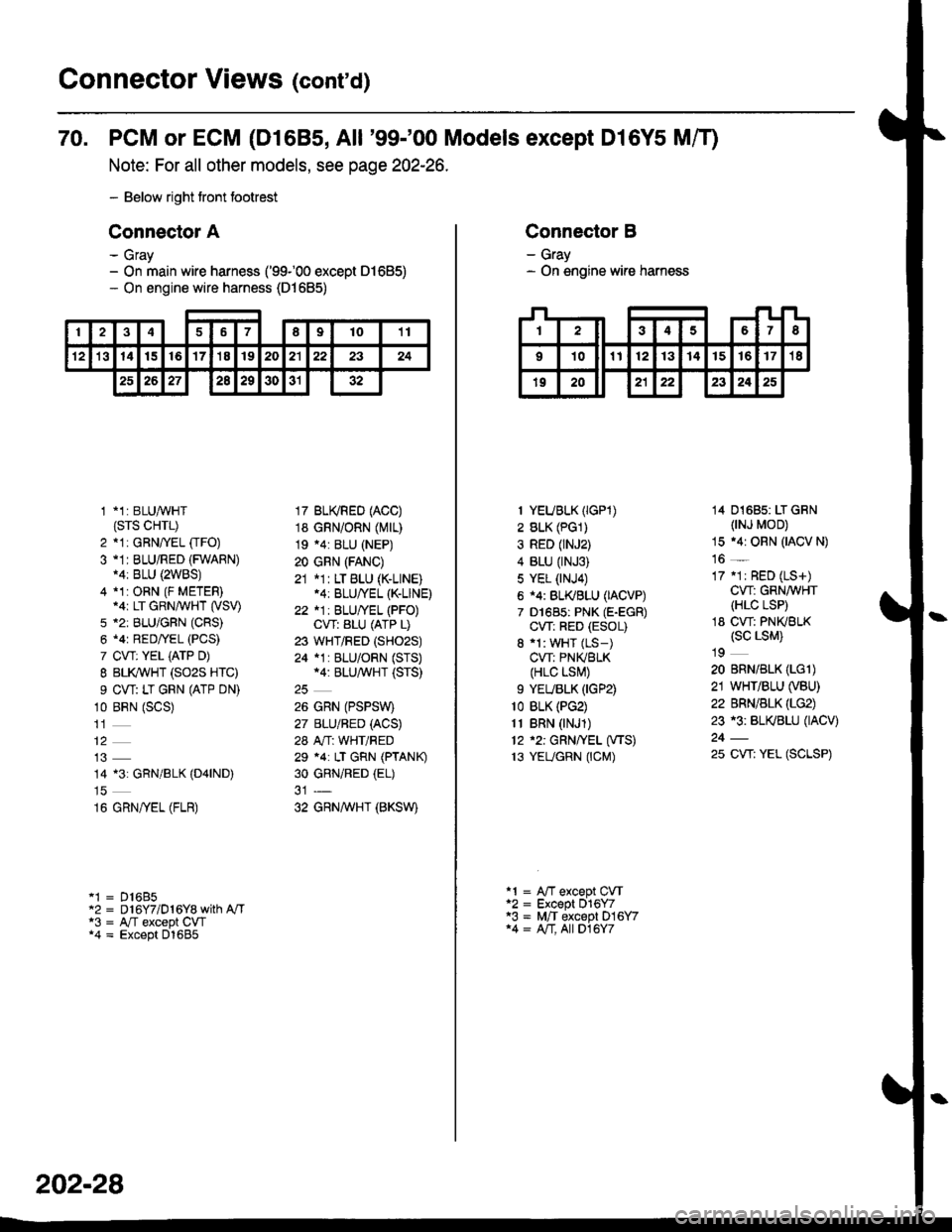
Connector Views (conrd)
70. PCM or ECM (D1685, All '99-'00 Models except Dl6Y5 Mff)
Note: For all other models, see page 202-26.
- Below right tront footrest
Connector A
- Gray- On main wire harness ('99100 except 01685)- On engine wire harness (D1685)
246789t011
't21314t516'17'18192021222324
2526272a29303132
1 *1: BLUAVHT(srs cHrL)
2 *1: GRNffEL [rFO)3 -1I BLU/RED (FWARN)14: BLU {2WBS)4 *1:ORN (F METER).ar LT GRN/WHT (VSV)
5 *2: BLU/GFN (CRS)
6 .4r RED/YEL (PCS)
7 CVT: YEL iATP D)
I BLI(WHT (SO2S HTC)
9 CW: LT GRN (ATP DN)
10 BRN (SCS)
14 13: GRN/BLK (D4|ND)
16 GRN/yEL (FLR)
'1 = D16B5"2 = D 16Y7/D 1 6Y8 with A"/Ta3 = A,/T except CW*4 = Except D1685
17 BU(RED (ACC)
18 GRN/ORN (Mrr)
19 .4: BLU (NEP)
20 GRN (FANC)
21 *1: LT BLU (K-LINE).4: BLU/YEL (K-LINE)
22 *1: BLU/YEL (PFO)CVT: ALU (ATP L)
23 WHT/RED (SHO2S)
24 *1 : BLU/ORN (STS)*4: BLU/^,iVHT (STS)
26 GRN (PSPSW)
27 BLU/BED (ACS)
28 A"/T: WHT/RED
29 *4: LT GRN (PTANK)
30 GRNiRED (EL)
32 GRNAVHT (BKSW)
202-28
Connector B
- Gray- On engine wire harness
I YEUBLK (IGP1)
2 BLK (PG1)
3 RED (rNJ2)
4 BLU (rNJ3)
5 YEL (NJ4)
6 i4: BL(BLU (IACVP)
7 D1685: PNK (E-EGR)
CW: RED (ESOL)
8 'l: WHT (LS-)
CVT: PNIVBLK(HLC LSI\,!)
9 YEUBLK (IGP2)
1o BLK (PG2)
11 BRN (NJ1)
12 '2: GRN/YEL (VTS)
13 YEUGRN (CM)
14 01685: LT GRN(NJ MOD)
15 .4r ORN (IACV N)
16 _
17 .1r RED (LS+)
CW: GRN/WHT(HLC LSP)
18 CW: PNKBLK(sc LsM)
19
20 BRN/BLK (LGl)
21 WHT/BLU (VBU)
22 BRN/BLK (LG2)
23 r3: BL(BLU (IACV)
25 CW: YEL (SCLSP)
a1 = A"fT except CVTa2 = Except 016Y7'3 = M,/T except D16Y714 = A/T, All D16Y7