ecm HONDA CIVIC 1999 6.G Workshop Manual
[x] Cancel search | Manufacturer: HONDA, Model Year: 1999, Model line: CIVIC, Model: HONDA CIVIC 1999 6.GPages: 2189, PDF Size: 69.39 MB
Page 1586 of 2189
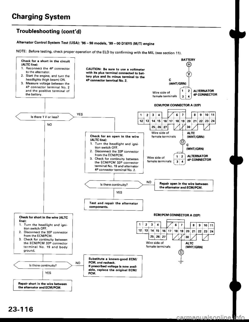
Charging System
Troubleshooting (cont'd)
Alternator Control System Test (USA): ,96 - 98 modets, ,99 _ 00 Dl6y5 (M/Tl engine
NorE: Before testing. check proper operation of the ELD by confirming with the MrL {see section r 1).
BATTERY
CAUTION: Be 3ure to use a voltmot€.with its plus terminal connected to b.t-tery plus and its minus terminal to the{P connectoi tgmrinal No. 2.c
{WHT/GRNt
Wire side oIfemale terminals
ALTERNATOR.P CONNECTOB
Check for a 3hort in the circuitIALTC linel:1. Reconnect the 4P connectorto the alternator,2. Stan the engine, and turn theheadlights {high beam) ON.3. Measure voltage between the4P connector terminal No. 2and the positive terminal ofthe battery.
ls there 1V or less?
Check for rn opon in tha wire(ALTC linol:1. Turn the headlight and igni-tion switch OFF.2. Disconnect the 32P connectortrom the ECM/PCN4.3. Check tor continuity betweenthe ECM/PCM 32P connectorterminal No. 19 and alternator4P connector terminal No. 2.
Bspair open in thg wire lrstweenthe rhern.tor .nd ECM/PCM.
Check for short in the wire (ALTClinel:1. Turn the headlight and ignition switch OFF.2. Disconnect the 32P connectortrom the ECM/PCM.3. Check tor continuity betweenthe ECM/PCM 32P connectorterminal No. 19 and bodyground.
Subslitute a known-good ECM/PCM, .nd .och6ck.It p.escribod vohago i! now avail-able, replace the original ECM/PCM.
Ropair 3hort in the wiro betweonthe ahe.nator and ECM/PCM.
ECM/PCM CONNECTOR A I32PI
'Ia18I1011
121314151718t9
7
202'l2221
262730
Wire side offemale terminalsALTC(WHT/GRNI
c{WHT/GRNI
ALTERNATORWire side oIfemale terminals
([l
T
12
1
ECM/PCM CONNECTOB A (32PI
I23478910t1
1213 14151617182021222321
262730
Wire side of I AITCfemate terminats
A
(WHT/GRN|
23-116
Page 1587 of 2189
-
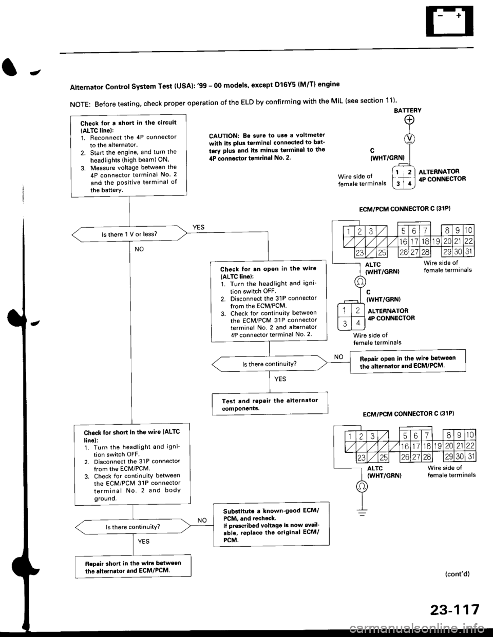
Alternator Control System Test {USA}: '99 - 0O models, except Dl6Y5 {M/T} engine
NOTE: Before testing, check proper operation ofthe ELD by confirming with the MIL (see section 11)'
BATTERY
CAUTION: Be sura lo use a voltmeter
with its plus te.minal conneqted io bat-
tery plus and it3 minus tgrminal to ths
4P connoctot tomrinal No. 2.
Wire side of
female terminals
c(WHT/GRNI
wire side offemale terminals
ALTERNATOR.P CONNECTOR
ECM/PCM CONNECTOR C 13lPI
ECM/PCM CONNECTOR C (31PI
(cont'd)
23-117
Check lor a sho.t in the circuit
{ALTC line):1, Beconnect the 4P connector
to the alternator.
2. Start the engine, and turn the
headlights (high beam) ON.
3. Measure voltage between the
4P connector terminal No. 2
and the Positive terminal of
the battery.
ls there 1 V or less?
Chcck for rn opon in the wire(ALTC lin6l:1. Turn the headlight and igni-
tion switch OFF
2. Disconnect the 31P connector
trom the ECM/PCM.
3. Check for continuity betlveen
the ECM/PCM 31P connectorterminal No. 2 and alternator
4P connector terminal No. 2
Repair opcn in the wire botweon
the alternstoi.nd ECM/PCM.ls there continuity?
Check tor short in the wire IALTC
line):1. Turn the headlight and igni-
tion switch OFF2. Disconnect the 31P connector
from the ECM/PCM.
3. Check for continuity between
the ECM/PCM 31P connector
terminal No. 2 and body
ground.
Substitute a known'good ECM/
PCM, and recheck.It prscribed voltagg is now avail'
abl€, replace tho original ECM/
PCM.
Raoair short in the wite between
the alle.nator and ECM/PCM,
1235618I10
/11611lo191 zo2122
23252621?82930JI
ALTC Wire side of(WHT/GRN) female terminals
o
Page 1597 of 2189
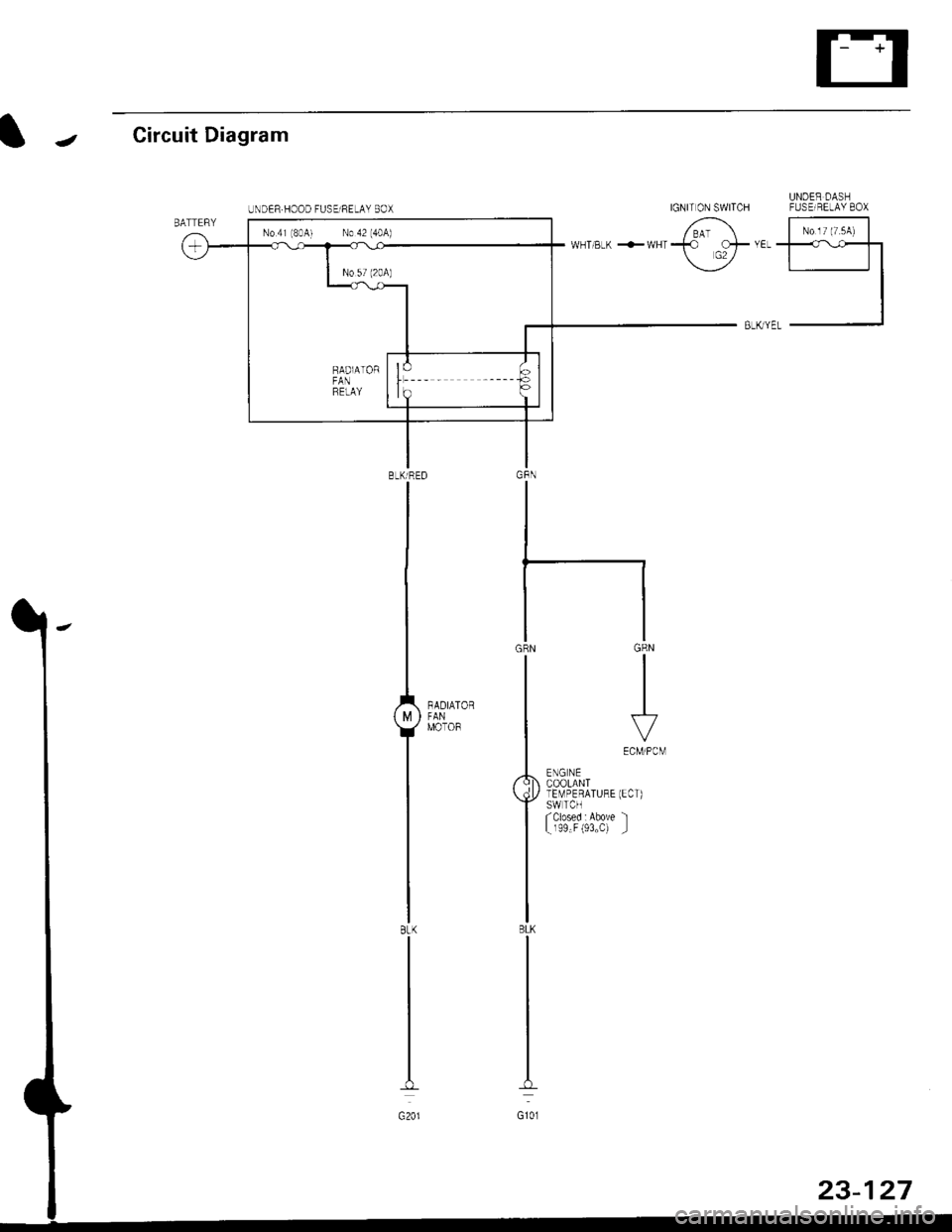
IJCircuit Diagram
UNDER DASHIGNIT ON SWITCH FUSEIRELAY 8OX
6 |-;;;;lii "ir"'t*Tl-l
BLK yEL -J
GRN
III
I
\.7VECM/PCM
ENG NECOOLANTlEMPERATURE (ECT)SWTCHfclosed : Above 'l
L r99"F (93"C) _l
BLKTRED
I
I
1,,*"_
T-'
IBtK
I
I
G201
UNDER.HOOD FUSElRELAY BOX
No 41 (8041 No 42 (40A)
Page 1604 of 2189
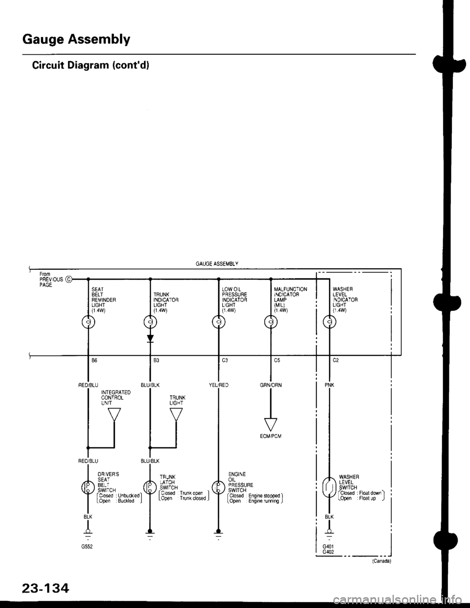
Gauge Assembly
Circuit Diagram (cont'dl
MATFUNCTIONINOICATOR
(M r)
WASHERLEVELSWITCHTclosed :Floatdownltopen Floal up .l
PNK
BLK
T
G401G402
GRN/ORN
I
ECM/PCM
ENGINEorLPRESSURESWITCHfcbsed Enqine
BLU/BLK YEURED
HI
'f''#lu""',.'f
--
RED/BLU
| ffitt'*'
IV
tl
tl
REDi BLU
I o, u,,,
/h,, SEii
Y rtt'J"T,r.0,.*"0
I
topen Buchred
BLK
T
G552
Page 1611 of 2189
J
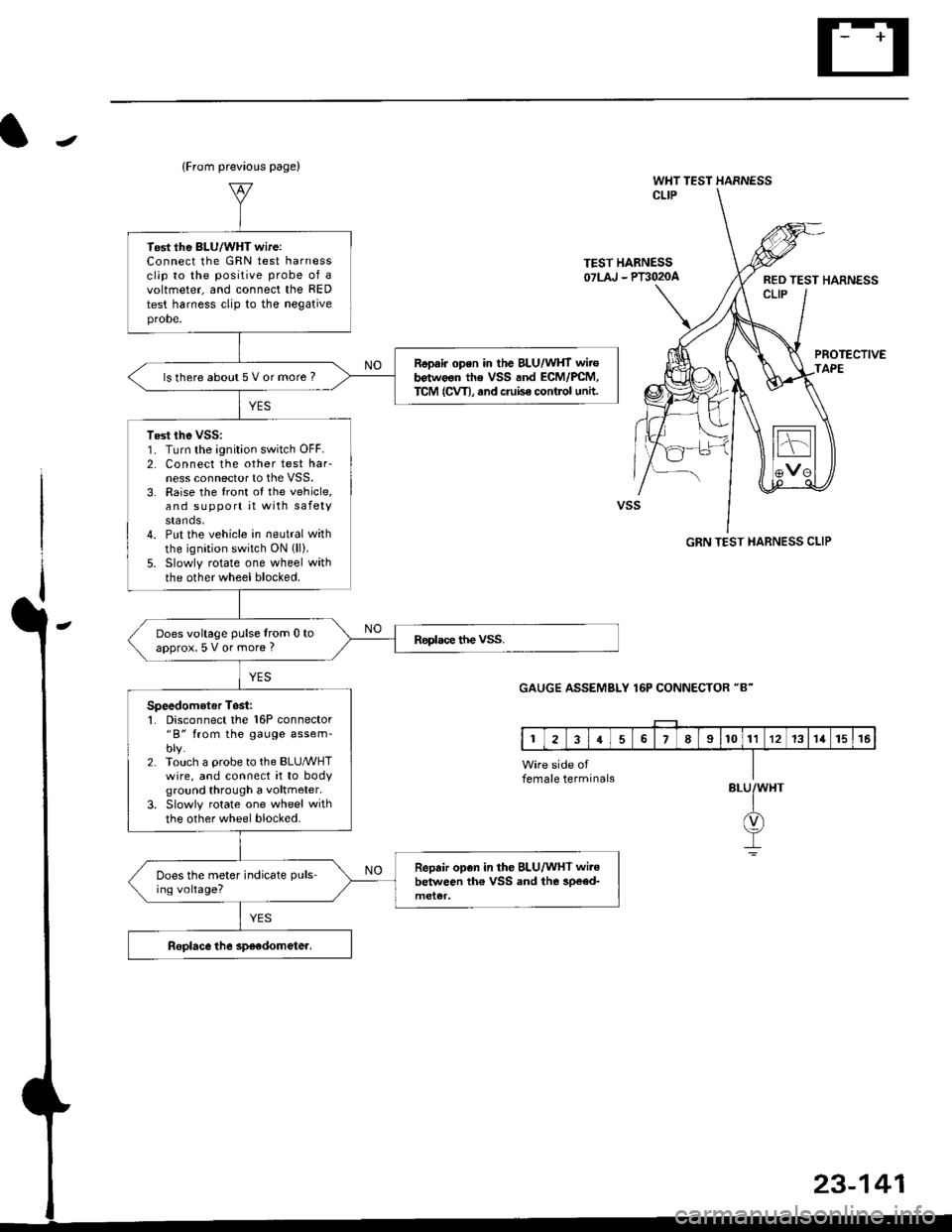
(From prevaous page)
WHT TEST HARNESSCLIP
TEST HABNESS07LAJ - Plil020aRED TEST HARNESSCLIP
PROTECTIVEAPE
GRN TEST HARNESS CLIP
GAUGE ASSEMBLY 16P CONNECTOR "8"
BLU
23-141
Tost the BLU/WHT wireiConnect lhe GRN test harnessclip to the positive probe of avoltmeter, and connect the RED
test harness clip to the negativeprobe.
Repair open in the BLU/WHT wirob€twoon the VSS and ECM/PCM,TCM (CVT), and cruise control untt.ls there about 5 V or more ?
Test the vss:1. Turn the ignition switch OFF.2. Connect the other test harness connector to the VSS.3. Raise the front ot the vehicle,and support it with safetystands,4. Put the vehicle in neutral with
the ignition switch ON (ll).
5. Slowly rotate one wheel withthe other wheel blocked.
Does voltage pulse from 0 toapprox.5 V or more ?
Speedometer Tosii'1. Disconnect the 16P connector"B" from the gauge assem-blv.2. Touch a probe to the BLUMHTwire, and connect it to bodyground through a voltmeter.
3. Slowly rotate one wheel with
the other wheel blocked.
Repair open in the BLU/WHT wi.ebelween th€ VSS and the 3pe€d-Does the meter indicate puls-
ing voltage?
female terminals
Page 1623 of 2189
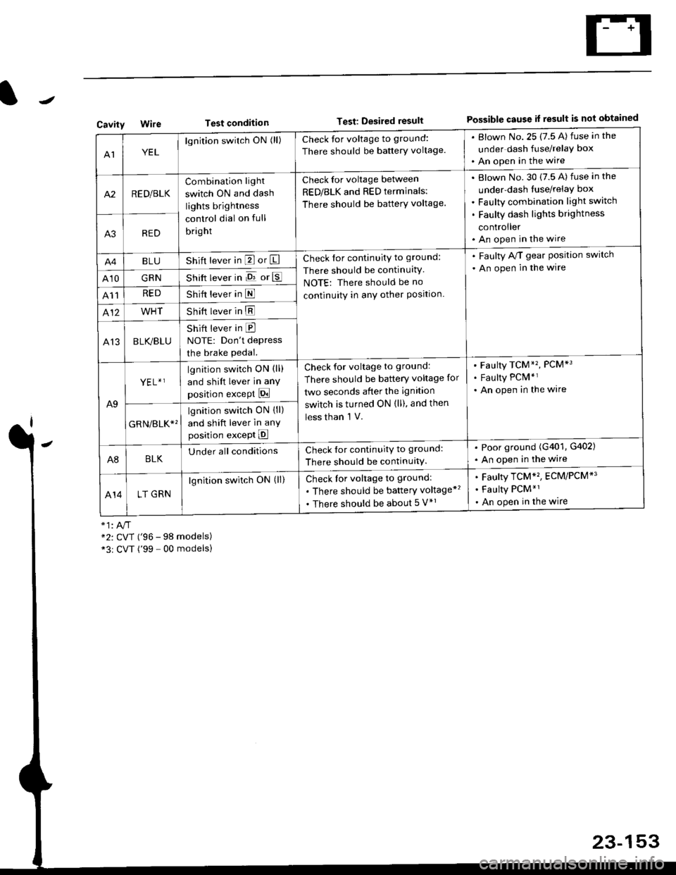
Test conditionTest: Desired resultPossible cause it result is not obtainedCavity
AIYEL
lgnition switch ON (ll)Check for voltage to ground:
There should be banerY voltage.
. Blown No.25 (7.5 A) fuse in the
under dash fuse/relay box
. An open in the wire
A2RED/BLK
Combination light
switch ON and dash
lights brightness
control dial on full
bright
Check for voltage between
RED/BLK and RED terminals:
There should be batterY voltage.
Blown No. 30 {7.5 A) fuse in the
under-dash tuse/relay box
Faulty combination light switch
Faulty dash lights brightness
controller
An open in the wireA3RED
BLUShift lever in P or ICheck for continuity to ground:
There should be continuitY
NOTE: There should be no
continuity in anY other Position.
. Faulty A/T gear Position switch
. An open in the wire
A10GRNShift lever in E or E
A11REDShift lever in E
412WHTShift lever in E
A13BLK/BLU
Shift lever in E
NOTE: Don't depress
the brake pedal.
A9
YEL+ ]lgnition switch ON (ll)
and shift lever in any
position except Pi
Check for voltage to ground:
There should be battery voltage for
two seconds after the ignition
switch is turned ON (ll), and then
less than 'l V.
Faulty TCM*'�, PCM*3
Faulty PCM*r
An open in the wire
GRN/err*'
lgnition switch ON {ll)
and shift lever in anY
position except E
A8BLKUnder all conditionsCheck for continuitv to ground:
There should be continuitY.
. Poor ground (G401, G402)
. An open in the wire
414LT GRN
lgnition switch ON (ll)Check for voltage to ground:
. There should be baftery voltage*'�
. There should be about 5 V*r
Faulty TCM*'�, ECM/PCM*'
Faulty PCM*1
An open in the wire
*2: CVT ('96 - 98 models)*3r CVT ('99 - 00 modelsl
23-153
Page 1744 of 2189
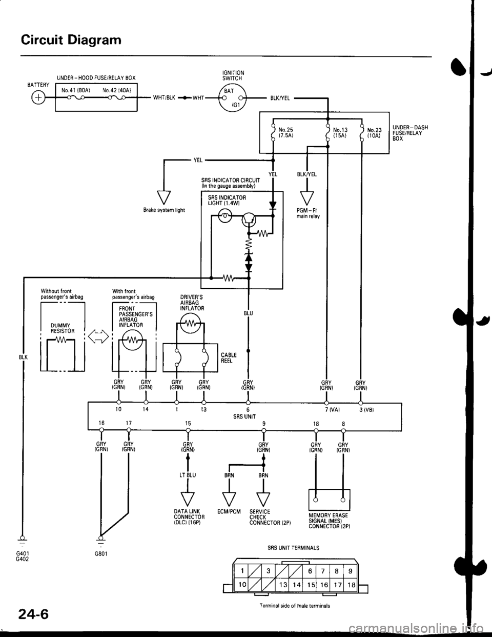
Circuit Diagram
UNDER-HOOD FUSE/RELAY 8OXIGNITIONSWITCH
WHT/8LI( +WHT
Brake systsm light
passenger's airbag
l----ltlI DUMMY II BESISTOR I
tll
tl
la rl
MEMORY ERASESIGNAT IMES)CONNECTOR I2P)
GRY{GRN)
I
BRN BRN
tl.-l- .-r-\./ \./
ECM/PCM SERVICECHECKCONNECTOR
ILT 8LU
I
t'7
DATA LINKCONNECTOR{DLC) {r6P)
GRY GRY(GRN) IGNN)
V:
G801
Teminalside oi thal€ terminals
24-6
4''
SRS UNIT TERMINALSG40tG402
SBS INDICATOR CIRCUIT{ln the gauge assembly)
PGM_FI
DRIVER'SAIRBAGINFLATOR
10 14 r 13 6 7(VAl 3{VBlSRS UNIT16 17 t5 9 18 8
Page 1754 of 2189
Troubleshooting
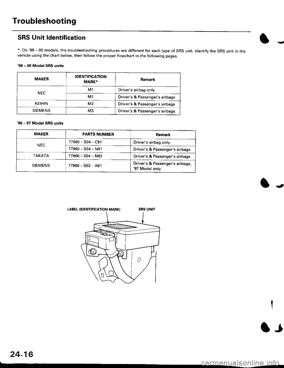
SRS Unit ldentification
+: On '98 - 00 models, the troubleshooting procedures are different for each type of SRS unit. ldentifv the SRS unit in thevehicle using the chart below, then follow the proper flowchan in the following pages.
'98 - 00 Model SRS units
MAKERIDENTIFICATION
MARK*Remark
NECM1Driver's airbag only
M1Driver's & Passenger's airbags
KEIHINM2Driver's & Passenger's airbags
SIEMENSM3Driver's & Passenger's airbags
'96 - 97 Model SRS units
LABEL IIDENTIFICATION MARK)
MAKERPARTS NUMBERRemark
NEC77960-S04-C81Driver's airbag only
77960-S04-N81Driver's & Passenger's airbags
TAKATA77960-S04-N82Driver's & Passenger's airbags
SIEMENS77960-S02-A81Driver's & Passenger's airbags,'97 Model only
24-16
lr
Page 1836 of 2189
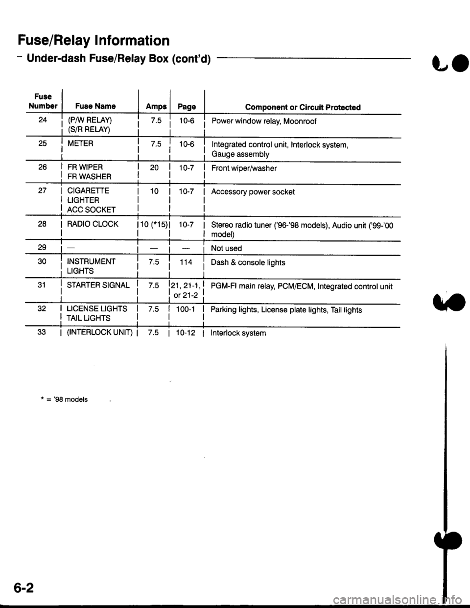
- Under-dash Fuse/Relay Box (cont'd)
Fuse/Relay I nformation
Fuse
NumberFuse NameAmps
(P/W RELAY)
(S/R RELAY)
FR WIPER
FR WASHER
LO
Page
10-7 |
I
Component or Clrcuit Protected
i Power window relay, Moonrool
Front wioer/washer
CIGARETTE
LIGHTER
ACC SOCKET
10-7Accessory power socket
I RAD|O CLOCK
I
110 115)l
tl
1O-7 |
I
Stereo radio tuner ('96198 models), Audio unit ('99100
model)
Not used
i 7.5i 114 iDash & console lights
I srnnrensrorunl | 7.slzl , zt -t , ! eCU-n main retay, PCM/ECM, Integrated controt unit
I ot 21-2 t
I LICENSE LIGHTS I 7.5
I rerr uesls I
Parking lights, License plate lights, Tail lights| 1oo-1 |
tl
| (f NTERLOCK UNIT) | 7.5 | 10-12 I Interlock system
* = '98 models
6-2
Page 1839 of 2189
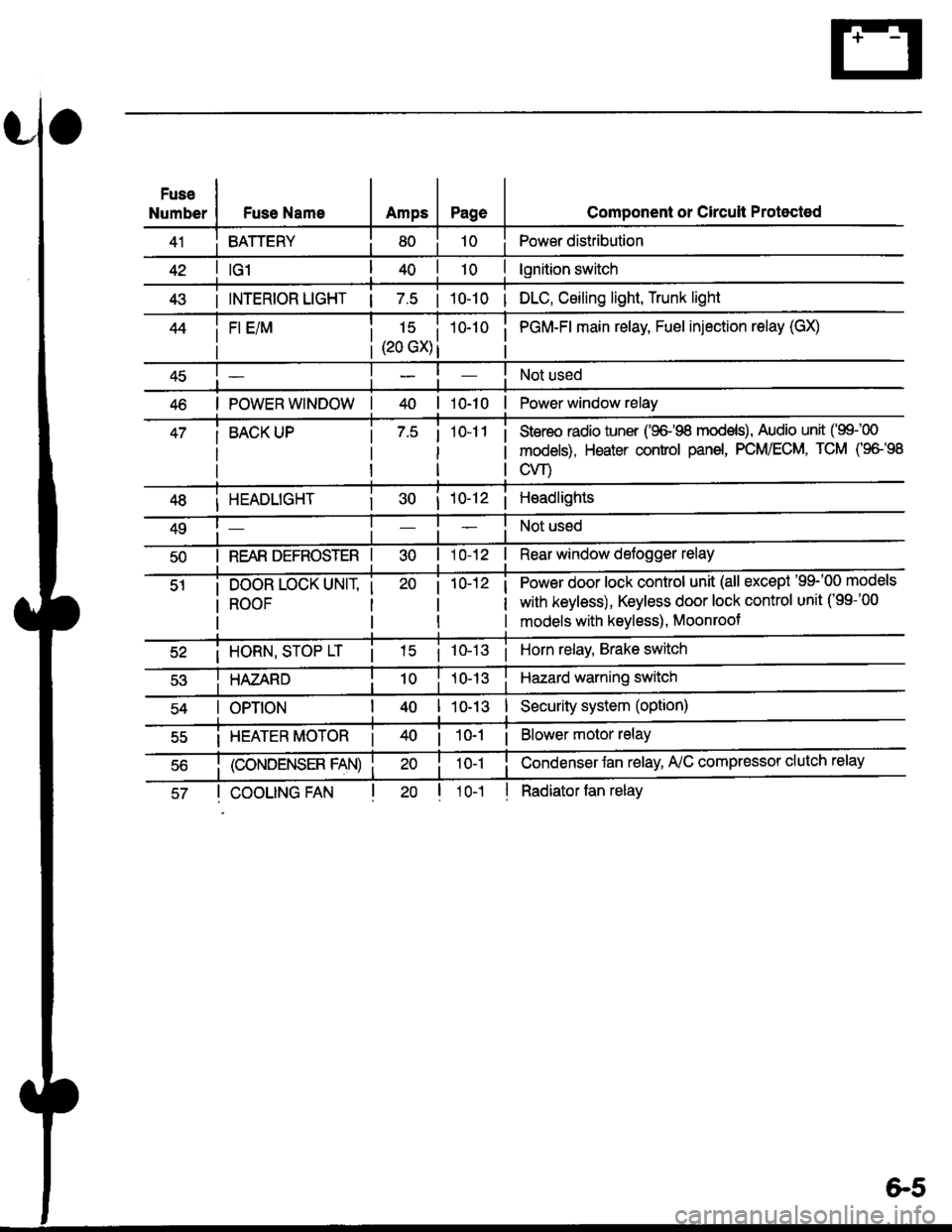
Fuse
NumberFuse NameAmpsPage
BATTERY
Component or Circult Protected
Power distribution
lgnition switch
INTERIOR LIGHT | 7.5 | 10-10 | DLC, Ceiling light, Trunk light
FI E/M15 i(20 GX) i
i PGM-FI main relay, Fuel injection relay (GX)
Not used
POWER WINDOW| 10-10 | Power window relay
BACK UPStereo radio iuner ('9G'98 mod€ls), Audio unit ('99100
models), Heater control panel, PCM/ECM, TCM (9e'98
cvr)
HEADLIGHT
REAR DEFROSTER I
DOOR LOCK UNIT,
ROOF
i 10-12i Headlights
Not used
Rear window defogger relay
Power door lock control unit (all except '99-'00 models
with keyless), Keyless door lock control unit ('99-'00
models with keyless), Moonroof
i HORN, SrOP Lri 10-13i Horn relay, Brake switch
HAZARDHazard warning switch
OPTIONI 10-13I Security system (option)
i HEATER MOTOR Ii 10-1 i Blower motor relay
(CONDENSER FAN)
COOLING FANl1o-1
Condenser Jan relay, A'lC compressor clutch relay
Radiator tan relay
&5