check engine HONDA CIVIC 1999 6.G Workshop Manual
[x] Cancel search | Manufacturer: HONDA, Model Year: 1999, Model line: CIVIC, Model: HONDA CIVIC 1999 6.GPages: 2189, PDF Size: 69.39 MB
Page 1393 of 2189
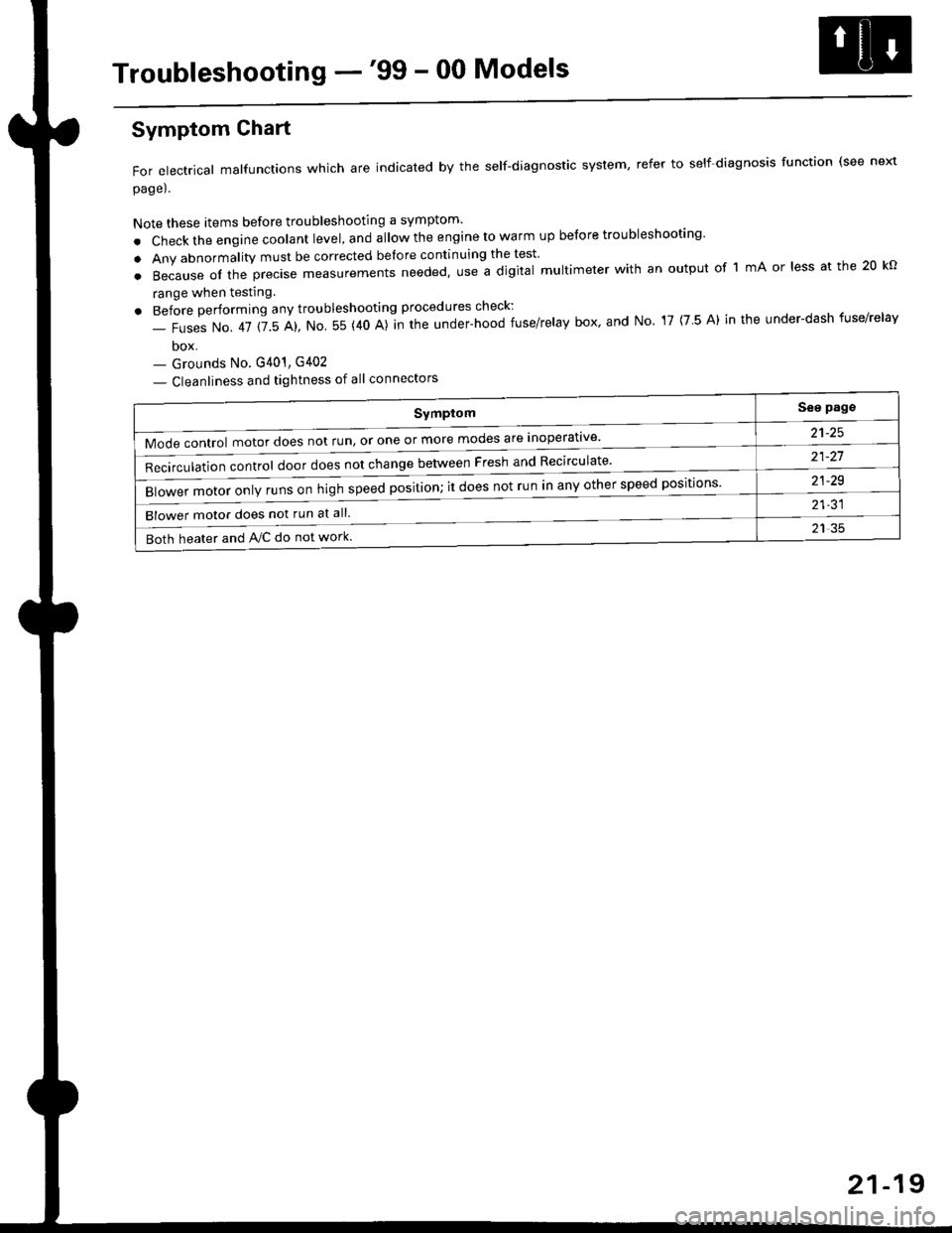
Troubleshooting -'99 - 00 Models
Symptom
Mode control motor does not run, or one or more modes are inoperat've'
Recirculation control door does not change between Fresh and Recirculate'
Blower motor only runs on high speed position; it does not run in any other speed positions
Blower motor does not run at all.
Both heater and Ay'C do not work
See pags
a1_tq
21-21
21-29
21-31
21 35
Symptom Chart
For electrical malfunctions which are indicated by the self-diagnostic system, refer to self-diagnosis function (see next
page).
Note these items before troubleshooting a symptom'
. Check the engine coolant level, and allow the engine to warm up before troubleshooting'
. Any abnormality must be corrected before continuing the test
.Becauseoftheprec|semeasurementsneeded,UseadigitaImu|timeterwithanoutputoflmAor|essatthe20ko
range when testing
. Before performing any troubleshooting procedures check:
- Fuses No. 41 115 Al, No 55 (40 A)]n the under-hood fuse/relay box' and No 17 (7 5 A) in the under-dash fuse/relav
box- Grounds No. G401, G402
- Cleanliness and tightness of all connectors
21-19
Page 1442 of 2189
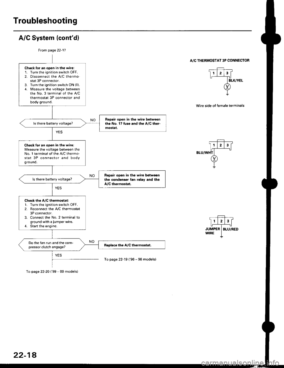
Troubleshooting
A/C System (cont'd)
From page 22-11
. _Ff,, __
I11213[
,r,il*"-T",-.r-'..owrRE I
To page 22-19 1'96 - 98 models)
A/C THERMOSTAT 3P CONNECTOR
Wire side oI female terminals
Check tor an open in the wire:1. Turn the ignition switch OFF.2. Disconnect the A/C thermostat 3P connector.3. Turn the ignition switch ON (ll).
4. Measure the voltage betweenthe No. 3 terminal of the Ay'Cthermostat 3P connector andbody ground.
Repai. open in the wire betweentho No. 17 tuso and the A/C the.-mostat.
Check loi an open in the wi.e:Measure the voltage between theNo. 1 terminal of the A,/C thermostat 3P connector and bodyground,
Ropair open in the wire betwoenthe condedlo. lan rolay and theA/C thormostat.
ls there battery voltage?
Check the A/C th6rmostat:1. Turn the ignition switch OFF.2. Reconnect the A,/C thermostat3P connector.3. Connect the No. 2 terminal toground with a iumperwire.4. Start the engine.
Do the fan run and the com-pressor clutch engage?
To page 22-20 ('99 - 00 models)
22-18
Page 1467 of 2189
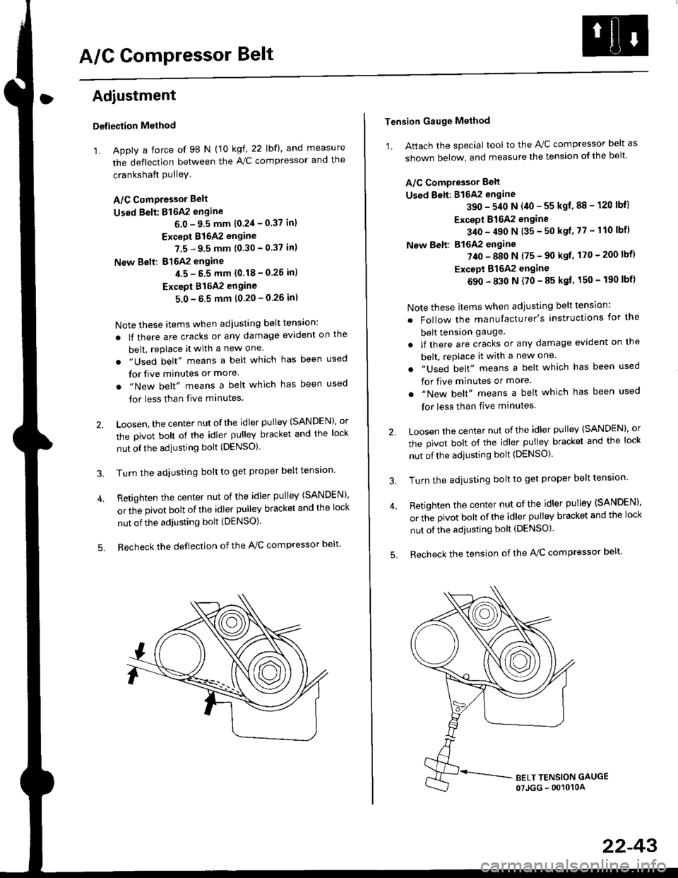
A/G GomPressor Belt
Adjustment
Detlection Method
'1. Apply a force of 98 N (10 kgf, 22 lbf), and measure
the deflection between the A,/C compressor and the
crankshaft PulleY
A/C ComPressor Belt
Used Belt: 816A2 engine
6.0 - 9.5 mm 10 2'l - 0.37 inl
Except 816A2 engine
7.5 - 9.5 mm (0.30 - 0.37 in)
New Belt: 816A2 engine
4.5- 6 5 mm (0.18-0.26 in)
Except 815A2 engine
5.0-5 5 mm (0.20-0.26 inl
Note these items when adjusting belt tens'on:
. lf there are cracks or any damage evident on the
belt, replace it with a new one.
. "Used belt" means a belt which has been used
for five minutes or more.
. "New belt" means a belt which has been used
tor less than five minutes.
2. Loosen, the center nut ofthe idler pulley (SANDEN), or
the pivot bolt of the idler pulley bracket and the lock
nut ofthe adjusting bolt (DENSO).
3. Turn the adjusting bolt to get proper belt tension'
4. Retighten the center nut of the idler pulley (SANDEN),
or the pivot bolt of the idler pulley bracket and the lock
nut of the adjusting bolt (DENSO).
5. Recheck the deflection of the A,/C compressor belt'
Tension Gauge Method
1. Attach the special tool to the IVC compressor belt as
shown below, and measure the tension of the belt
A/C Compressor Belt
Used Belt: 816A2 engine
390 - 540 N (40 - 55 kgf, 88 - 120 lbll
Except 816A2 engine
340 - 490 N (35 - 50 ksf, 77 - 110 lbfl
New Belt: B16A2 engine
?40 - 880 N {75 - 90 ksf' 170 - 200 lbf)
Except Bl642 engine
690 - 830 N (70 - 85 ksf, 150 - 190 lbf)
Note these items when adjusting belt tension:
. Follow the manufacturer's instructions for the
belt tension gauge.
. lf there are cracks or any damage evident on the
belt, rePlace it with a new one.
. "Used belt" means a belt which has been used
for five minutes or more.
. "New belt" means a belt which has been used
for less than five minutes
2 Loosen the center nut of the idler pulley (SANDEN)' or
the pivot bolt of the idler pulley bracket and the lock
nut of the adjusting bolt (DENSO).
3. Turn the adjusting bolt to get proper belt tension
4. Retighten the center nut of the idler pulley (SANDEN),
or the pivot bolt of the idler pulley bracket and the lock
nut of the adjusting bolt (DENSO)
5. Recheck the tension of the A/C compressor belt'
22-43
Page 1473 of 2189
Troubleshooting
ll.
Tips and Precautions
Bef ore Troubleshooting
. Check applicable fuses in the appropriate fuse/relay
box.
. Check the battery for damage, state of charge, and
clean and tight connections.
. Check the alternator belt tension.
CAUTION:
. Do not quick-charge a battery unless the battery
ground cable has been disconneqted, otherwise you
will damage the alternator diodes.
. Do not attempt to crank the engine with the battery
ground cable loosely connecled or you will severely
damage the wiling,
Handling Connectois
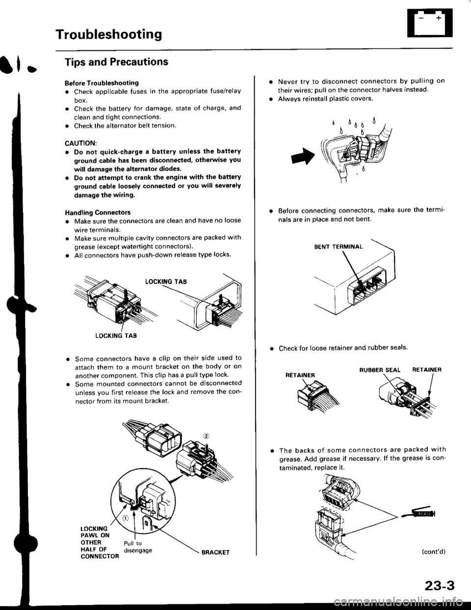
. Make sure the connectors are clean and have no loose
wire terminals.
. Make sure multiple cavity connectors are packed with
grease (except watertight connectors)
. All connectors have push-down release type locks.
Some connectors have a clip on their side used to
attach them to a mount bracket on the body or on
another component. This clip has a pulltype lock.
Some mounted connectors cannot be disconnected
unless you first release the lock and remove the con-
nector from its mount bracket.
LOCKINGPAWL ONOTHERHALF OFCONNECTOR
Pull todrsengage
LOCKING TAB
BRACKET
Never try to disconnect connectors by pulling on
their wires; pull on the connector halves instead
Alwavs reinstall plastic covers.
Before connectang connectors,
nals are in place and not bent.
make sure the terml-
. Check for loose retainer and rubber seals.
RETAINER
The backs of some connectors are packed with
grease. Add grease if necessary. lf the grease is con-
taminated, replace it.
(cont'd)
23-3
Page 1508 of 2189
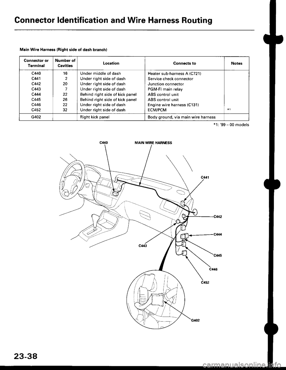
Gonnector ldentification and Wire Harness Routing
Msin Wire Harness (Right side oI dash branch)
Connector or
Terminal
Number of
CavitiesLocationConnects toNotes
c440
c441
c442
c443
c4M
c445
c446
c452
16
2
20
7
22
22
Under middle of dash
Under right side of dash
Under right side of dash
Under right side of dash
Behind right side of kick panel
Behind right side of kick panel
Under right side of dash
Under right side of dash
Heater sub-harness A (C721)
Service check connector
Junction connector
PGM-Fl main relay
ABS control unit
ABS control unit
Engine wire harness (C131)
ECM/PCM
G402Right kick panelBody ground, via main wire harness
*'l: '99 - 00 models
23-38
Page 1565 of 2189
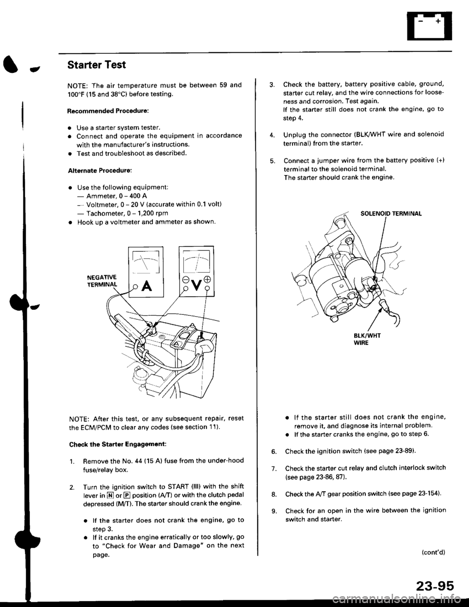
-Starter Test
NOTE; The air temoerature must be between 59 and
100'F (15 and 38"C) before testing.
Recommended Procedure:
. Use a staner system tester.
. Connect and operate the equipment in accordance
with the manufacturer's instructions.
. Test and troubleshoot as described,
Alternate Procedurg:
. Use the following equipment:- Ammeter, 0 - 400 A
- Voltmeter, 0 - 20 V (accurate within 0.1 volt)
- Tachometer, 0 - 1,200 rpm
. Hook up a voltmeter and ammeter as shown.
NEGATIVETERMINAL
NOTE: After this test, or any subsequent repair. reset
the ECM/PCM to clear any codes (see section l1)
Check the Start€r Engagemont:
1. Remove the No. 44 (15 A) fuse from the under-hood
fuse/relay box,
2. Turn the ignition switch to START (llll with the shift
lever in E or E position (rVT) or with the clutch pedal
depressed {M/T). The starter should crank the engine.
. lf the starter does not crank the engine, go to
step 3.
. lf itcranksthe engineerraticallyortooslowly, go
to "Check for Wear and Damage" on the next
page.
Check the battery. battery positive cable, ground,
starter cut relay, and the wire connections for loose-
ness and corrosion, Test again.
lf the starter still does not crank the engine, go to
step 4,
Unplug the connector (BLK,/WHT wire and solenoid
terminal) from the starter,
Connect a jumper wire from the battery positive (+)
terminal to the solenoid terminal.
The starter should crank the engine.
. lf the starter still does not crank the engine,
remove it, and diagnose its internal problem
. lf the startercranksthe engine, goto step 6.
Check the ignition switch (see page 23-891.
Check the starter cut relay and clutch interlock switch
(see page 23-86,87).
Check the A/f gear position switch (see page 23-154).
Check for an open in the wire between the ignition
switch and starter.
7.
(cont'd)
23-95
9.
Page 1566 of 2189
Starting System
Starter Test lcont'dl
Ch€ck tor Wear and Damage
The starter should crank the engine smoothly and
steadily, lf the starter engages. but cranks the engine
erratically, remove it, and inspect the starter drive gear
and torque converter or flywheel ring gear for damage.
. Check the drive gear overrunning clutch for binding
or slipping when the armature is rotated with the
drive gear held,- lf damaged. replace the gears.
Check Cranking Voltsge and Curr€nt Draw
Cranking voltage should be no less than 8.5 volts.
Current draw should be no more than 350 amperes.
lf cranking voltage is too low, or current draw too high,
check for;
. dead or low batterv.
. open circuit in starter armature commutator seg-
ments,
. starter armature dragging.
. shorted armature winding.
o excessive drag in engine.
Check Cranking rpm
Engine speed during cranking should be above 100 rpm,
lf speed is too low, check for:
. loose battery or stanerterminals.
. excessively worn starter brushes,
. open circuit in commutator segments.
o dirty or damaged helical spline or drive gear.
. defective drive gear overrunning clutch.
Check Siarter Disengag€ment
With the shift lever in El or @ position (A/T) or with the
clutch pedal depressed (M/T), turn the ignition switch to
START (lll), and release to ON (ll).
The starter drive gear should disengage from the torque
converter or flywheel ring gear when you release the
Key.
lf the drive gear hangs up on the torque converter or fly-
wheel ring gear, check for:
. solenoid plunger and switch malfunction,
. dirty drive gear assembly or damaged overrunning
clutch.
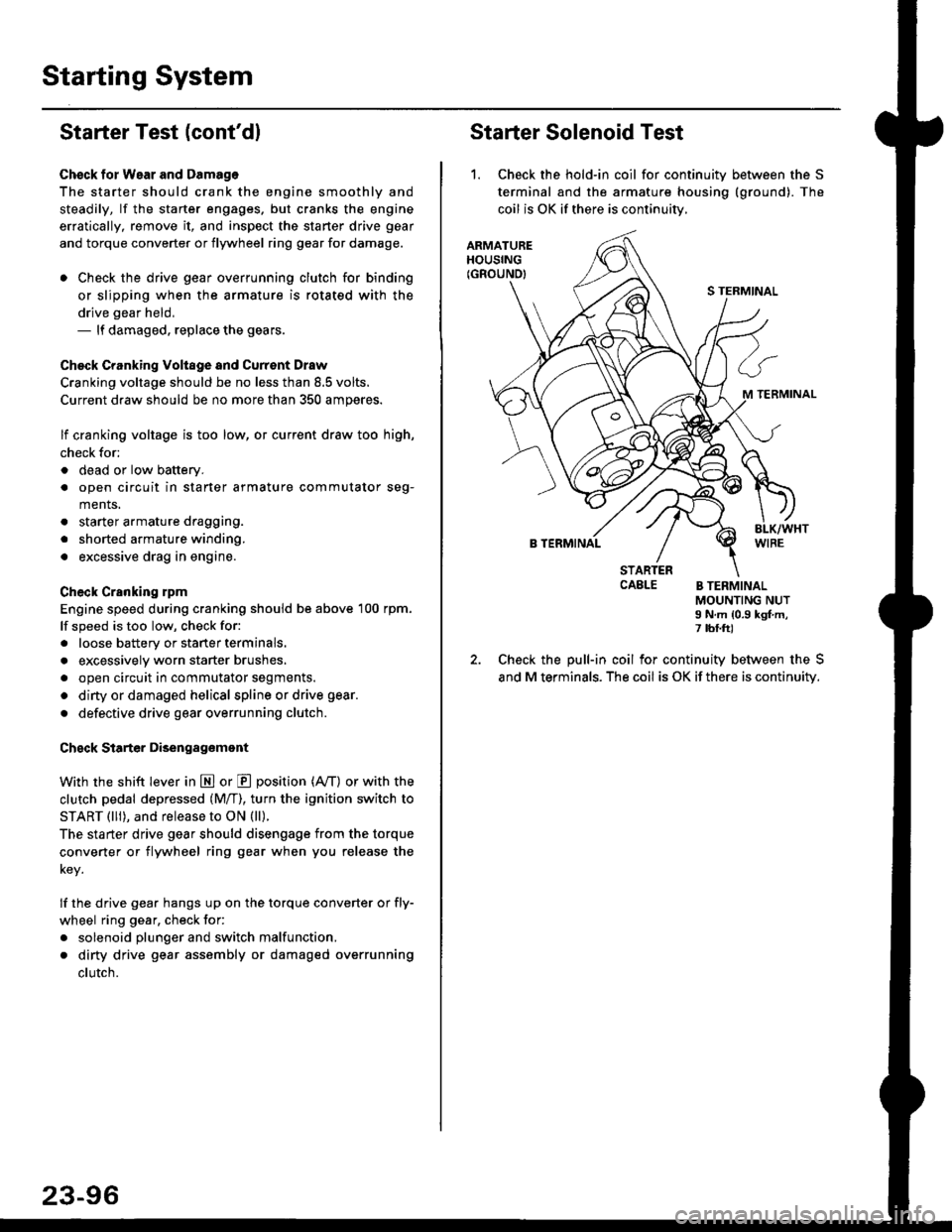
Starter Solenoid Test
1. Check the hold-in coil for continuitv between the S
terminal and the armature housing (ground). The
coil is OK if there is continuitv,
ARMATUREHOUSING(GROUND)
S TERMINAL
M TERMINAL
B TERMINAL
STARTERCAELE B TERMINALMOUNTING NUTI N.m {0.9 kgf.m,7 tbf.ft)
Check the pull-in coil for continuity between the S
and M terminals. The coil is OK if there is continuity.
Page 1575 of 2189
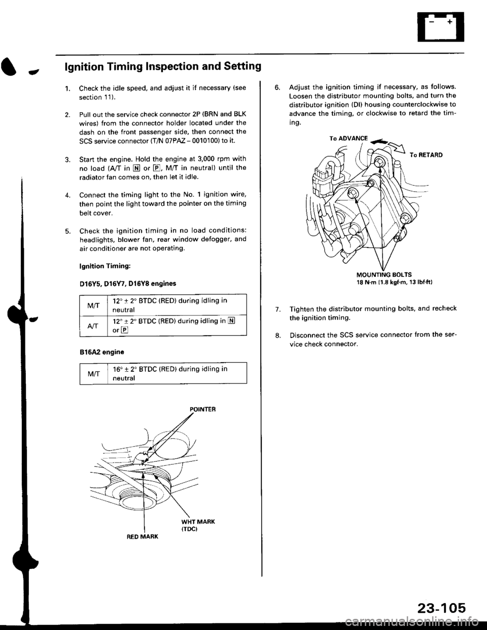
-lgnition Timing Inspection and Setting
1.Check the idle speed, and adjust it it necessary (see
section 'l '1 ).
Pull out the service check connector 2P (BRN and BLK
wires) from the connector holder located under the
dash on the front passenger side, then connect the
SCS service connector (T/N 07PAZ - 0010'100) to it.
Start the engine. Hold the engine at 3.000 rpm with
no load {A,/T in E or E. M/T in neutral) until the
radiator fan comes on, then let it idle.
Connect the timing light to the No. 1 ignition wire,
then point the light toward the pointer on the timing
belt cover.
Check the ignition timing in no load conditions:
headlights. blower fan, rear window defogger, and
air conditioner are not operating.
lgnhion Timing:
D15Y5. D16Y7, Dl6Yg engines
816A2 engine
MIT16" 12' BTDC (RED) during idling in
neutral
M/T12't 2" BTDC (RED) during idling in
neutral
l2'r 2" BTDC {RED) during idling in S
orE
POINTEB
RED MARK
23-105
ro ADVANCE -<;,
6. Adjust the ignition timing if necessary, as follows.
Loosen the distributor mounting bolts. and turn the
distributor ignition (Dl) housing counterclockwise to
advance the timing, or clockwise to retard the tim-
ing.
MOUNTING BOLTS18 N'm (1.8 kgfm, 13lblftl
Tighten the distributor mounting bolts, and recheck
the ignition timing.
Disconnect the SCS service connector from the ser-
vice check connector.
7.
Page 1586 of 2189
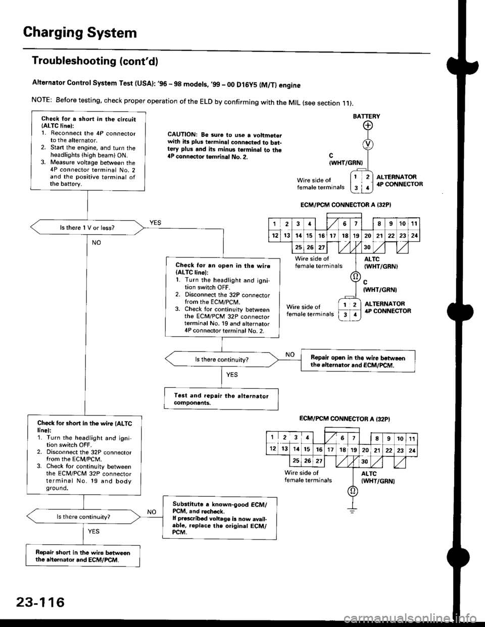
Charging System
Troubleshooting (cont'd)
Alternator Control System Test (USA): ,96 - 98 modets, ,99 _ 00 Dl6y5 (M/Tl engine
NorE: Before testing. check proper operation of the ELD by confirming with the MrL {see section r 1).
BATTERY
CAUTION: Be 3ure to use a voltmot€.with its plus terminal connected to b.t-tery plus and its minus terminal to the{P connectoi tgmrinal No. 2.c
{WHT/GRNt
Wire side oIfemale terminals
ALTERNATOR.P CONNECTOB
Check for a 3hort in the circuitIALTC linel:1. Reconnect the 4P connectorto the alternator,2. Stan the engine, and turn theheadlights {high beam) ON.3. Measure voltage between the4P connector terminal No. 2and the positive terminal ofthe battery.
ls there 1V or less?
Check for rn opon in tha wire(ALTC linol:1. Turn the headlight and igni-tion switch OFF.2. Disconnect the 32P connectortrom the ECM/PCN4.3. Check tor continuity betweenthe ECM/PCM 32P connectorterminal No. 19 and alternator4P connector terminal No. 2.
Bspair open in thg wire lrstweenthe rhern.tor .nd ECM/PCM.
Check for short in the wire (ALTClinel:1. Turn the headlight and ignition switch OFF.2. Disconnect the 32P connectortrom the ECM/PCM.3. Check tor continuity betweenthe ECM/PCM 32P connectorterminal No. 19 and bodyground.
Subslitute a known-good ECM/PCM, .nd .och6ck.It p.escribod vohago i! now avail-able, replace the original ECM/PCM.
Ropair 3hort in the wiro betweonthe ahe.nator and ECM/PCM.
ECM/PCM CONNECTOR A I32PI
'Ia18I1011
121314151718t9
7
202'l2221
262730
Wire side offemale terminalsALTC(WHT/GRNI
c{WHT/GRNI
ALTERNATORWire side oIfemale terminals
([l
T
12
1
ECM/PCM CONNECTOB A (32PI
I23478910t1
1213 14151617182021222321
262730
Wire side of I AITCfemate terminats
A
(WHT/GRN|
23-116
Page 1587 of 2189
-
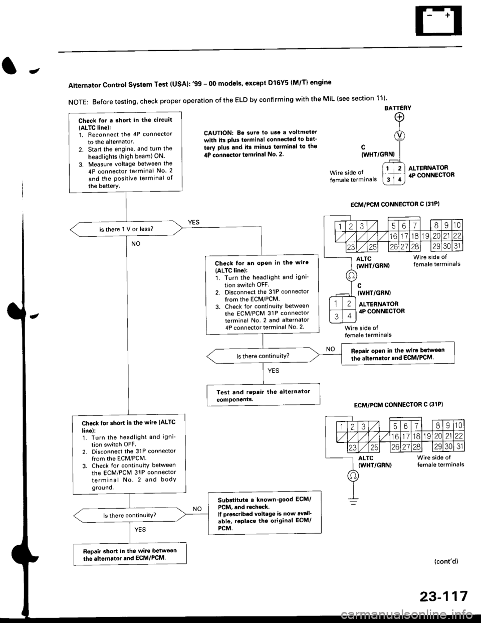
Alternator Control System Test {USA}: '99 - 0O models, except Dl6Y5 {M/T} engine
NOTE: Before testing, check proper operation ofthe ELD by confirming with the MIL (see section 11)'
BATTERY
CAUTION: Be sura lo use a voltmeter
with its plus te.minal conneqted io bat-
tery plus and it3 minus tgrminal to ths
4P connoctot tomrinal No. 2.
Wire side of
female terminals
c(WHT/GRNI
wire side offemale terminals
ALTERNATOR.P CONNECTOR
ECM/PCM CONNECTOR C 13lPI
ECM/PCM CONNECTOR C (31PI
(cont'd)
23-117
Check lor a sho.t in the circuit
{ALTC line):1, Beconnect the 4P connector
to the alternator.
2. Start the engine, and turn the
headlights (high beam) ON.
3. Measure voltage between the
4P connector terminal No. 2
and the Positive terminal of
the battery.
ls there 1 V or less?
Chcck for rn opon in the wire(ALTC lin6l:1. Turn the headlight and igni-
tion switch OFF
2. Disconnect the 31P connector
trom the ECM/PCM.
3. Check for continuity betlveen
the ECM/PCM 31P connectorterminal No. 2 and alternator
4P connector terminal No. 2
Repair opcn in the wire botweon
the alternstoi.nd ECM/PCM.ls there continuity?
Check tor short in the wire IALTC
line):1. Turn the headlight and igni-
tion switch OFF2. Disconnect the 31P connector
from the ECM/PCM.
3. Check for continuity between
the ECM/PCM 31P connector
terminal No. 2 and body
ground.
Substitute a known'good ECM/
PCM, and recheck.It prscribed voltagg is now avail'
abl€, replace tho original ECM/
PCM.
Raoair short in the wite between
the alle.nator and ECM/PCM,
1235618I10
/11611lo191 zo2122
23252621?82930JI
ALTC Wire side of(WHT/GRN) female terminals
o