ac line HONDA CIVIC 1999 6.G Workshop Manual
[x] Cancel search | Manufacturer: HONDA, Model Year: 1999, Model line: CIVIC, Model: HONDA CIVIC 1999 6.GPages: 2189, PDF Size: 69.39 MB
Page 1286 of 2189
Moonroof
1.
2.
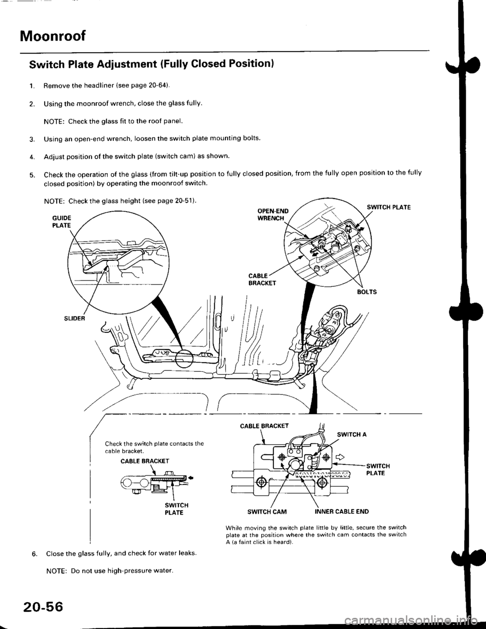
Switch Plate Adjustment (Fully Closed Positionl
3.
4.
5.
Remove the headliner {see page 20-64).
Using the moonroof wrench, close the glass fully.
NOTE: Check the glass fit to the rool panel.
Using an open-end wrench, loosen the switch plate mounting bolts.
Adjust position of the switch plate (switch cam) as shown.
Check the operation of the glass (from tilt-up position to fully closed position, from the fully open position to the fully
closed position) by operating the moonroof switch.
NOTE: Check the glass height (see page 20-51).SWITCH PLATE
GUIDEPLATE
SWITCH CAM
While moving the switch plateplate at the position where thea (a faint click is heard).
INNER CABLE END
little bv little, secure the switchswitch cam contacts the switch
Close the glass fully, and check for water leaks.
NOTE: Do not use high-pressure water.
CAELE BRACKET
20-56
Page 1288 of 2189
Interior
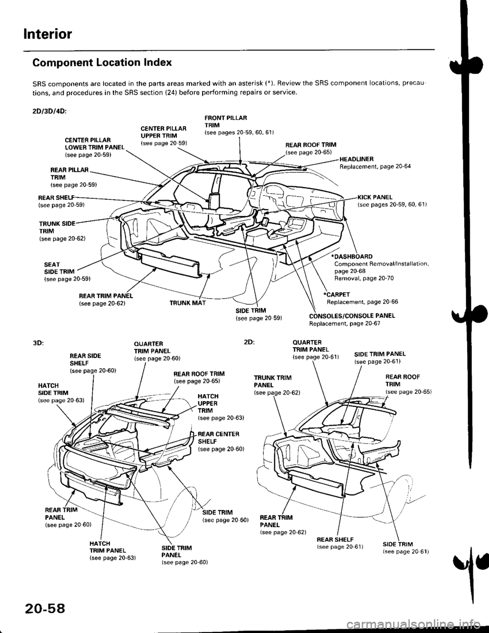
Component Location Index
SRS comDonents are located jn the parts areas marked with an asterisk (*). Review the SRS component locations, precau
tions, and procedures in the SRS section {24) before performing repairs or service.
2Dl3Dl4Dl
CENTER PILLARUPPER TRIM{see page 20 591
FRONT PILLARTRIM{see pages 20 59,60,61)
REAR PILLARTRIM
TRUNKTRIM(see page 20-62)
SEATSIDE TRIM{see page 20-59)
{see page 20 59}
CENTER PILLARLOWER TRIM PANEL(see page 20-59)
REAR ROOF TRIM(see page 20-65)
:
OUARTERTRIM PANEL
{see page 20'61)
HEADLINERReplacement, Page 20'64
*OASHBOARO
Component Removal/lnstallation,page 20 68
REARlsee page 20 59)
REAR TRIM PANEL
lsee page 20-62)
Removal, page 20-70
*CARPET
Replacement, page 20 66
PANELReplacement, page 20-67
3D:
REAR SIDESHEI-F(see page 20-60)
OUARTERTRIM PANEL(see page 20-60)SIDE TRIM PANEL(see page 20-6'l)
2Dl
HATCHSIDE TRIM(see pase 20 63)
REAR ROOF TRIM(see page 20 65)REAR ROOFTFIM(see page 20'65)HATCHUPPERTRIMlsee page 20 63)
CENTERSHELFlsee page 20 60)
REARPANELlsee page 20 60)
SIDE TRIM{see page 20 60)REARPANEL(see page 20 62)
1
HATCHTRIM PANEL(see page 20-63)
SIDE TRIMPANEL(see page 20-60)
20-54
Page 1294 of 2189
Headliner
Replacement
CAUTION: When prying with a flat-tip screwdriver,
wrap it with proioctiva tap€ to prevsnt damage.
NOTE:
. Take care not to bend and scratch the headliner.
. Be careful not to damage the dashboard and other
interior trim.
'1. Remove:
4D:
. Front pillar trim (both sides. see page 20-59)
. Center pillar lower trim panel (both sides, see page
20 59)
Upper anchor bolt from the front seat belt (both
sides, see page 20-85)
Center pillar outer trim and center pillar upper trim
(both sides, see page 20-59)
Ceiling light (see section 23)
Rearview mirror (see page 20-25)
a
a
a
a
a
3D:
. Front pillar trim (both sides, see page 20-60)
. Right rear seat-back and rear seat cushion (see
page 20-80)
. Rear center shelf (see page 20-60)
. Rear side shelf and side trim panel (right side,
see page 20-60)
. Upper anchor bolts from the front and rear seat
belts (right side. see pages 20-86, 89)
. Ouarter trim panel (right side, see page 20-60)
. Ceiling light (see section 23)
. Rearview mirror (see page 20-25)
2Dl
. Front pillar trim (both sides, see page 20-51)
. Right rear seat-back and rear seat cushion (see
page 20-81)
Side trim panel (right side, see page 20-61)
Upper anchor bolt from the front seat belt (right
side, see page 20-86)
Ouarter trim panel (right side, see page 20-6'l)
Ceiling light (see section 23)
Rearview mirror (see page 20-25)
20-64
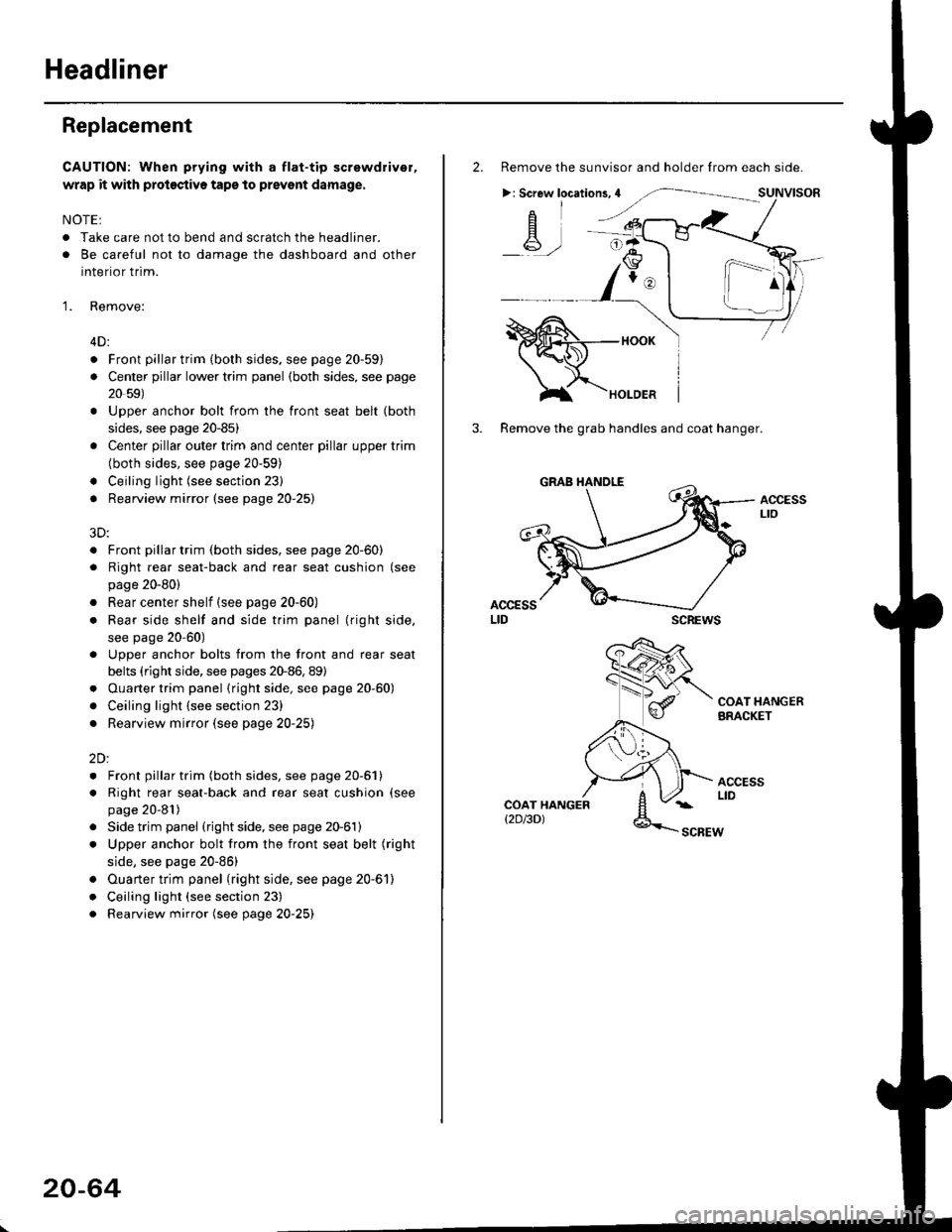
2. Remove the sunvisor and holder from each side.
>: Screw locations,4
-A-,-
3. Remove the grab handles and coat hanger.
scREws
ACCESSLto
COAT HANGERBRACKET
ACCESSLIDCOAT HANGERt2D/3DlSCBEW
1^
Page 1295 of 2189
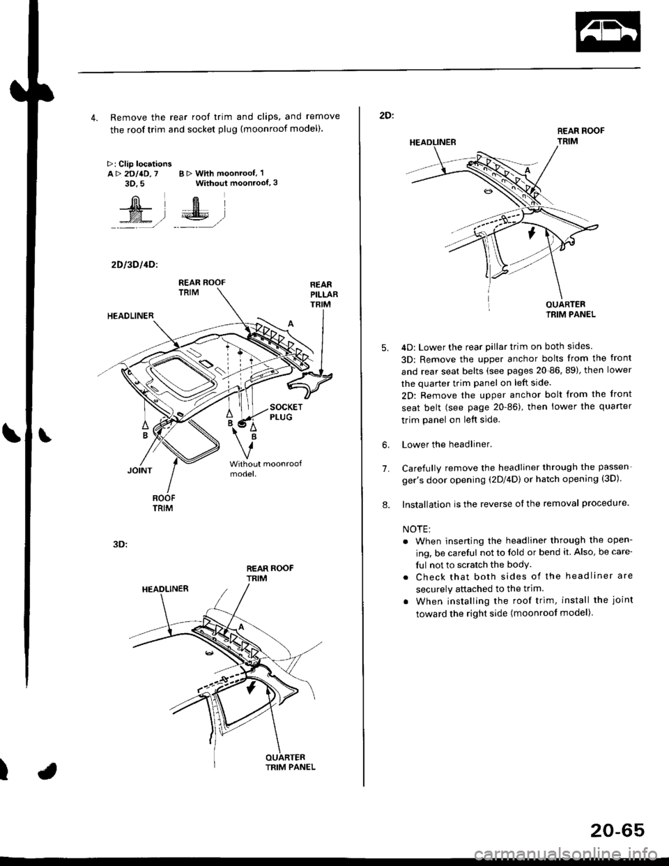
4. Remove the rear roof trim and clips, and remove
the roof trim and socket plug (moonroof model).
>: Clip locationsA> 2DllD,7 B > With moonroof, 'l
3D.5 Without moonroof,3
[il',fEl
t% .l €E .l':: =,/ _._- ,/
2D l3D l4Dl
REAR ROOFTRIM
3D:
t
REAR ROOF
TRIM
2D:
5.
7.
OUARTERIRIM PANEL
4D: Lower the rear pillar trim on both sides
3D: Remove the upper anchor bolts from the front
and rear seat belts (see pages 20-86, 89), then lower
the quarter trim panel on left side.
2D: Remove the upper anchor bolt from the front
seat belt (see page 20-86), then lower the quaner
trim panel on left side.
Lower the headliner.
Carefully remove the headliner through the passen-
ger's door opening (2Dl4D) or hatch opening (3D).
Installation is the reverse of the removal procedure.
NOTE:
. When inserting the headliner through the open-
ing, be careful not to fold or bend it. Also, be care-
ful not to scratch the bodY.
. Check that both sides of the headliner are
securely attached to the trim.
. When installing the roof trim, install the joint
toward the right side (moonroot model)
6.
8.
20-65
Page 1303 of 2189
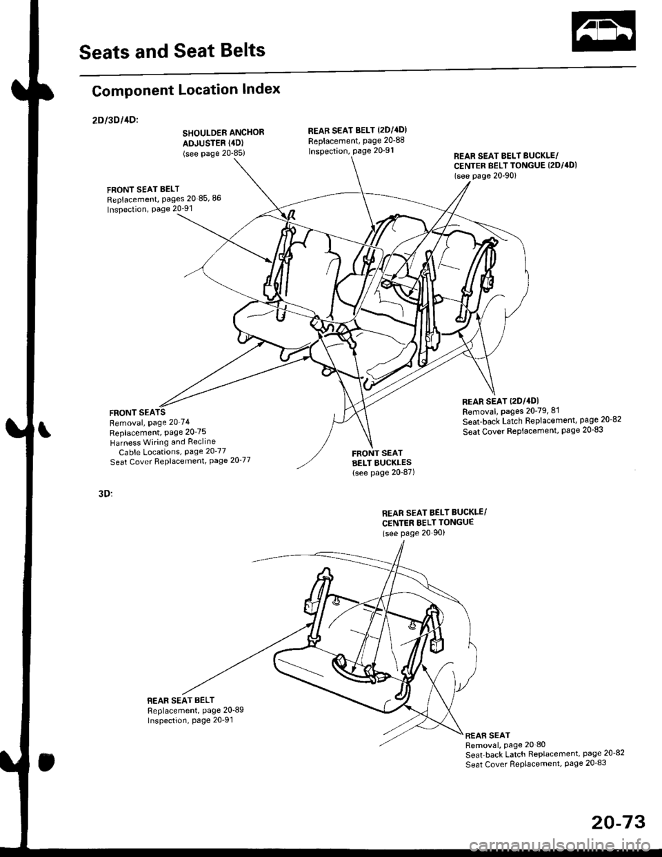
Seats and Seat Belts
Component Location Index
2Dl3Dl1Dl
SHOULDER ANCHOR
ADJUSTER (4D)
(see Page 20-85i
FRONT SEAT BELT
Replacement, Pages 20 85,86
Inspection, Page 20-91
FRONT SEARemoval, Page 20'74
Replacement, Page 20 75
Harness Wiring and Recline
Cable Locations, Page 20-77
Seat Cover RePlacemenl, Page 2O'77
3D:
BEAR SEAT BELTReplacement, Page 20'89Inspection, page 20-91
REAB SEAT BELT (2DI4DI
Replacement, page 20-88
lnspection, page 20-91REAR SEAT EELT BUCKLE/CENTER BELT TONGUE (2DI4DI
(see p6ge 20'90)
REAR SEAT t2Dl4DlRemoval, pages 20-79, 8'l
Seat-back Latch Replacement, page 20-82
Seat Cover RePlacement, Page 20-83
FRONT SEATBELT BUCKLES{see page 20-87)
REAR SEAT BELT BUCKLE/
CENTER BELT TONGUE(see Page 20'90)
REAR SEATRemoval, page 20 80
Seat back Latch Replacement, page 20-8?
Seat Cover RePlacement, Page 20_83
20-73
Page 1305 of 2189
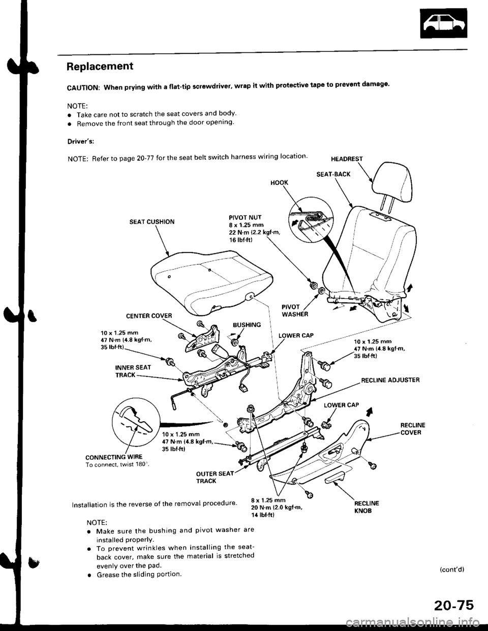
Replacement
CAUTION: When prying with a flat-tip screwdrivet, wrap it with protective tape to prevent damage'
NOTE:
. Take care not to scratch the seat covers and body
. Remove the front seat through the door openlng'
Driver's:
NOTE: Refer to page 2O-77 for the seat belt switch harness wiring location'
SEAT CUSHION
CENTER COVER
INNER SEATTBACK
PIVOT NUT8 x 1.25 mm22 N.m l.2.216 tbf.ft)
v
l
35 tbt.ft)
10 x 1.25 mm47 N.m {4.8 kgf m,10 x 1.25 mm47 N.m {i1.8 kgl m,35 tbr.ft)
RECLINE ADJUSTER
LOW
d
ER CAP
l
RECLINE
CONNECTING WIRETo connect, twist 180'
OUTER SEATTRACK
Installation is the reverse of the removal procedure'
NOTE:
. Make sure the bushing and pivot washer
installed ProPerly.. To prevent wrinkles when installing the seat-
back cover, make sure the material is stretched
evenly over the Pad.
. Grease the sliding Portion
8 x 1.25 mm20 N.m 12.0 kgf.m,14 tbt.ft)
are
RECLINEKNOB
(cont'd)
20-75
10 x 1.25 mm47 N.m {4.8 kgf'm,35 tbtftl
Page 1306 of 2189
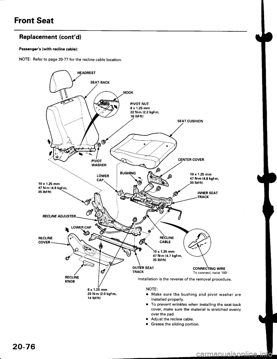
Front Seat
Replacement (cont'd)
Passenger's (with reclino cablel:
NOTE; Refer to page 20-77 for the recline cable location.
HEADREST
PIVOTWASHER
LOWERCAP
PIVOT NUT8 x 1.25 mm22 N.m 12,2 kgl.m,tbt.ftt
SEAT CUSHION
CENTER COVER
10 x 1,25 mm47 N.m (4.8 kgf.m,
10 x 1.25 mm47 N.m {4.8 kgf.m,3s tbt.ft)
INNER SEATTRACK
35 tbf.ftl
RECLINE ADJUSTEB
RECLINECOVER
i LowER CAP
bRECLINECABLE
x 1.25 mm47 N'm (4.7 kgf.m,35 tbtftl
SEAT
8 x 1.25 mm20 N.m {2.0 kgf.m,14 rbf.ft)
ruf, To connect, twist 180'.
lnstallation is the reverse of the removal procedure.
NOTE:
. Make sure the bushing and pivot washer are
installed properly.
. To prevent wrinkles when installing the seat-back
cover, make sure the material is stretched evenly
over the pad.
. Adjust the recline cable.
. G.ease the sliding ponion.
SEAT-BACK
20-76
Page 1307 of 2189
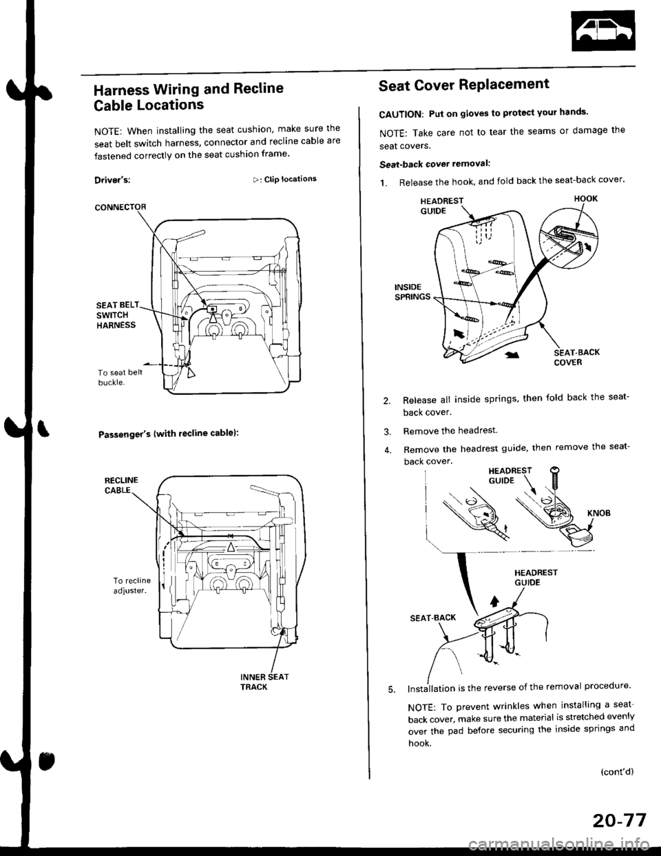
Harness Wiring and Recline
Cable Locations
NOTE: When installing the seat cushion, make sure the
seat belt switch harness, connector and recline cable are
fastened correctly on the seat cushion frame'
Driver's:>: Clip locations
Passenger's (with lecline cablel:
TRACK
Seat Cover RePlacement
CAUTION: Put on gloves to protest yout hands'
NOTE: Take care not to tear the seams or damage the
seat covers.
Seat-back cover removal:
1. Release the hook, and fold back the seat-back cover'
Release all inside springs, then fold back the seat-
back cover.
Remove the headrest.
Remove the headrest guide, then remove the seat-
back cover.
lnst;llation is the reverse of the removal procedure'
NOTE: To prevent wrinkles when installing a seat-
back cover, make sure the material is stretched evenly
over the pad before securing the inside springs and
hook.
3.
(cont'd)
20-77
HEADREST
Page 1344 of 2189
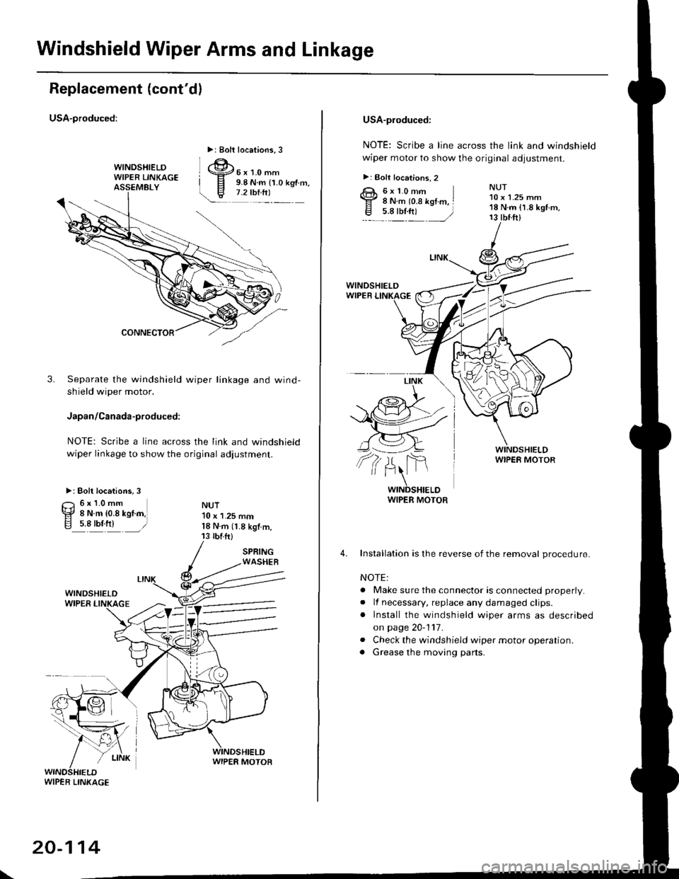
Windshield Wiper Arms and Linkage
Replacement (cont'dl
USA-produced:
3. Separate the windshield wiper linkage and wind-
shield wiper motor.
Japan/Canada-produced:
NOTE: Scribe a line across the link and windshield
wiper linkage to show the original adjustment.
>: Bolt locations, 3
O 6r1.0mm
EF 8 N.m {0.8 kstm,ig 5.8 tbf.ft) )
NUT10 x 1.25 mml8 N rn (1.8 kgtm,13 tbtftl
>r Bolt locations,3
WIPER LINKAG€
\
20-114
USA-produced:
NOTE: Scribe a line across the link and windshield
wiper motor to show the original adjustment.
>: Bolt locations, 2
R 6J( 1.0 mm
Y 8 N.m to.s kgtm, I
.E- 7Y.nt )
NUT10 x 1.25 mm'18 N.m {1.8 kgf.m.13 tbtft)
WINDSHIELDWIPER MOTOR
4. Installation is the reverse of the removal procedure.
NOTE:
. Make sure the connector is connected properly.
. lf necessary, replace any damaged clips.
. lnstall the windshield wiper arms as described
on page 20-1'17.
. Check the windshield wiper motor operation.. Grease the moving parts.
Page 1352 of 2189
Body ('97 model)
Front Seat Belt
Removal/lnstallatlon ....20-128
Rear Seat
RemovaUlnstallation ....20-126
Washer Tube
Windshield
fndex .......... 20-124
Outline of '97 Model Changes
The molding side seal was added.
The method of installing the rear seat cushion was changed (2Dl3D).
A middle floor gusset was added and the method of detaching the seat belt retractor was changed (2Dl3D)
The installation position of the washer tube was changed.