locknut HONDA CIVIC 1999 6.G Workshop Manual
[x] Cancel search | Manufacturer: HONDA, Model Year: 1999, Model line: CIVIC, Model: HONDA CIVIC 1999 6.GPages: 2189, PDF Size: 69.39 MB
Page 99 of 2189
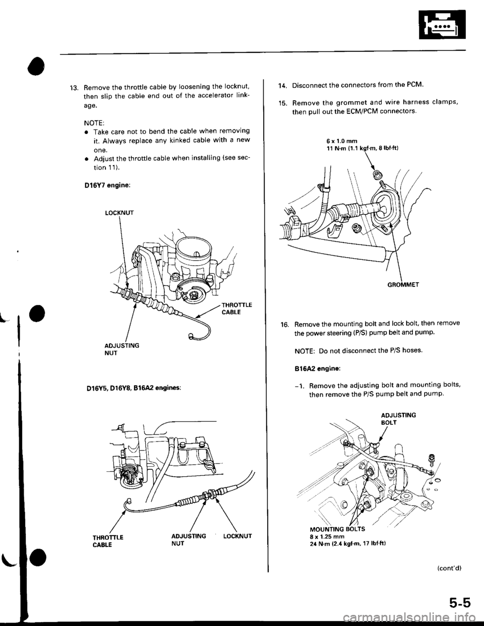
13. Remove the throftle cable by loosening the locknut,
then slip the cable end out of the accelerator link-
age.
NOTE;
. Take care not to bend the cable when removing
it. Always replace any kinked cable with a new
one.
. Adjust the throttle cable when installing (see sec-
tion 1 1).
D16Y7 engine:
D16Y5, D16Y8, B16A2 engines:
LOCKNUT
LOCKNUT
14,Disconnect the connectors from the PCM.
Remove the grommet and wire harness clamps,
then pull out the ECM/PCM connectors
6x1.0mm
16. Remove the mounting bolt and lock bolt, then remove
the power steering (P/S) pump belt and pump
NOTE: Do not disconnect the P/S hoses.
816A2 engine:
Remove the adjusting bolt and mounting boits,
then remove the P/S pump belt and pump
(cont'd)
5-5
AOJUSTING
Page 101 of 2189
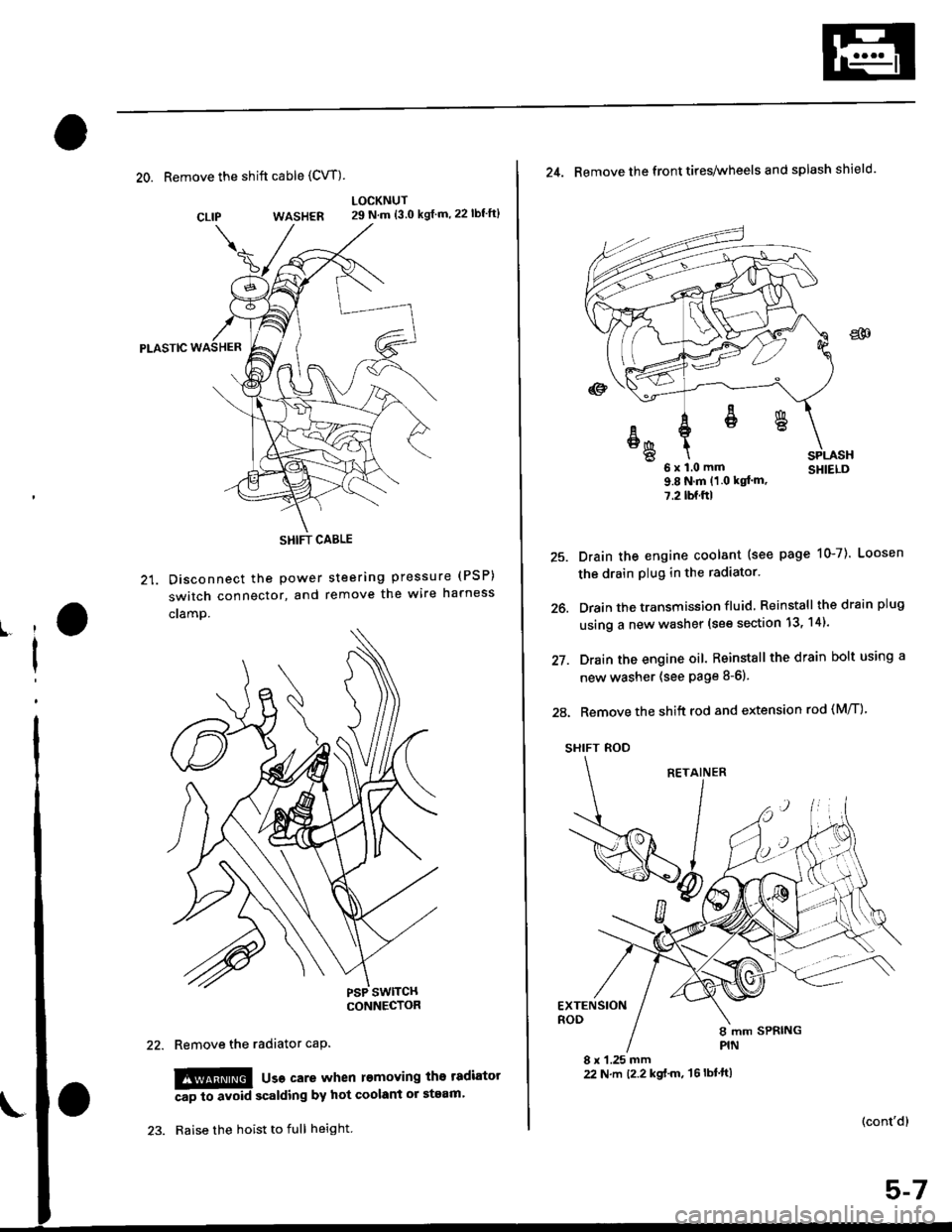
20. Remove the shift cable (CVT)
WASHER
Pt-Aslc
21. Disconnect the Power
switch connector, and
cramp.
LOCKNUT29 N.m {3.0 kgf m,22lbf'ft}
steering pressure (PSP)
remove the wire harness
CLIP
ll
I
Remove the radiator caP.
!!!@ usa care when l€moving the tadiator
Ap to avoid scalding by hot coolant or steam'
Raise the hoist to full height.
SHIFT CABLE
(cont'd)
25.
26.
27.
24. Remove the front tires/wheels and splash shield.
u x l.u mm SHIELD9.8Nm(1 0 kqt'm,
7.2lbf.ftl
Drain the engine coolant (see page 10-7). Loosen
the drain plug in the radiator.
Drain the transmission fluid Reinstall thedrainplug
using a new washer (see section 13, 14).
Drain the engine oil. Reinstall the drain bolt using a
new washer (see page 8-6).
28. Remove the shift rod and extension rod (M/T)
SHIFT ROD
EXTENSIONROD
8 x 1.25 mm22 N.m t2.2 kgf'm, 't6lbtft)
ER
6x1.0mm
Page 123 of 2189
Valve Clearance
Adjustment
NOTE:
. Valves should be adjusted only when the cylindsrhead temperature is less than 100"F (38"C).
. After adjusting, retorque the crankshaft pulley bolt(see page 6-16).
1, Remove the cylinder head cover.
NOTE; Refer to page e46 when installing the cytinderhead cover.
2. Remove the upper cover (see page 6-19).
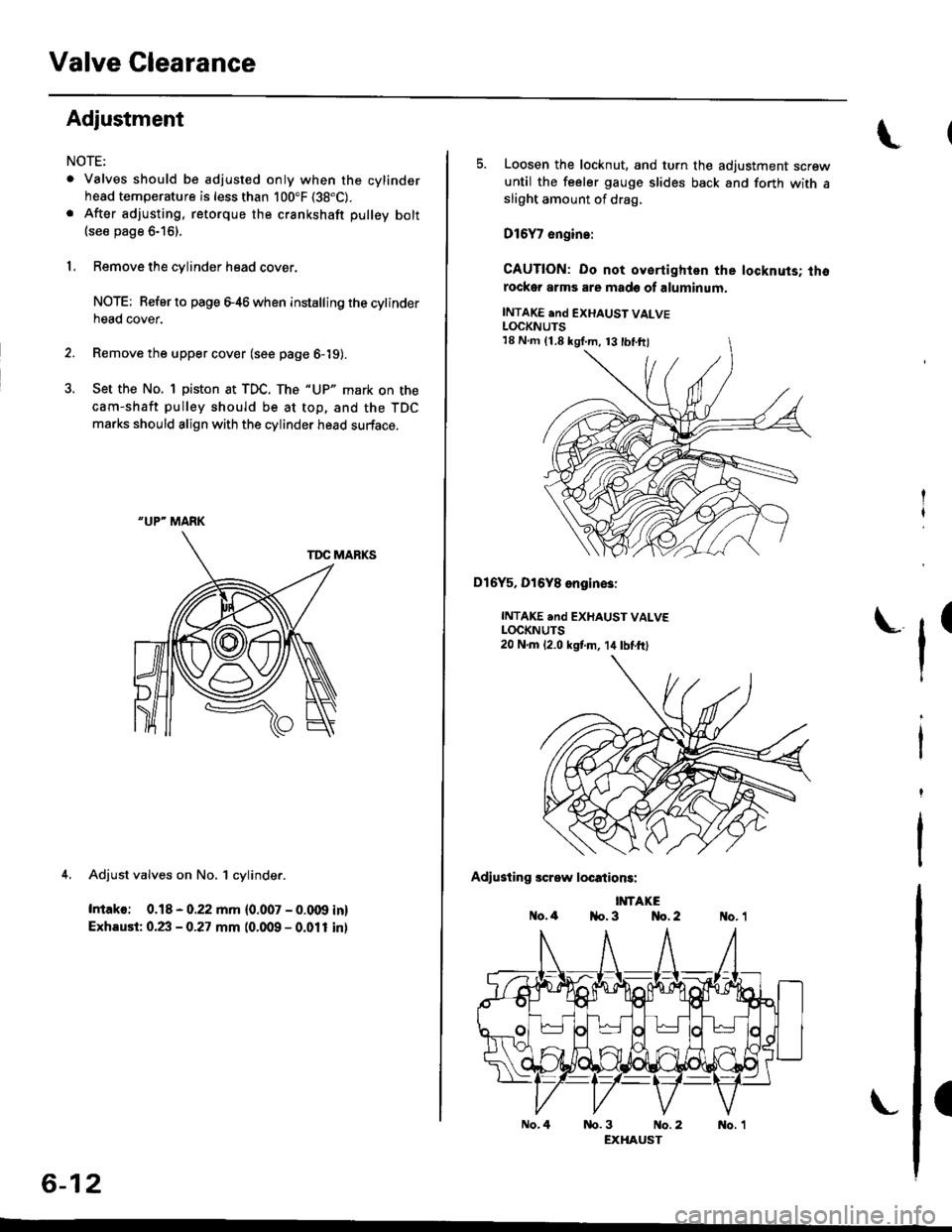
3. Set the No. 1 piston at TDC. The "UP" mark on the
cam-shaft pulley should be at top, and the TDC
marks should align with the cylinder head surface.
TDC MARKS
4. Adjust valves on No, 1 cylinder.
Intako: 0.18 - 0.22 mm {0.007 - 0.009 in}
Exhaust: 0.23 - 0.27 mm (0.009 - 0.011 inl
"UP" MARK
6-12
No.4
5. Loosen the locknut, and turn the adjustment screwuntil the feeler gauge slides back and forth with asliOht amount of drag,
D16Y7 engin.:
CAUTION: Do not oyertighlen the locknuts; thorockor arms are made of aluminum.
INTAKE end EXHAUST VALVELOCKNUTS
Dl6Y5, Dl6Y8 engin€3:
INTAKE .nd EXHAUST VALVELOCKNUTS20 N.m 12.0 kstm, 14lbtft)
Adiusting screw locations:
IMTAKEo.4 1{o. 3 No. 2
tr'
(
nb.3 No.2 No. 1EXHAUST
18 N.m (1.8 kgI.m, 13 tbl.ftl
Page 124 of 2189
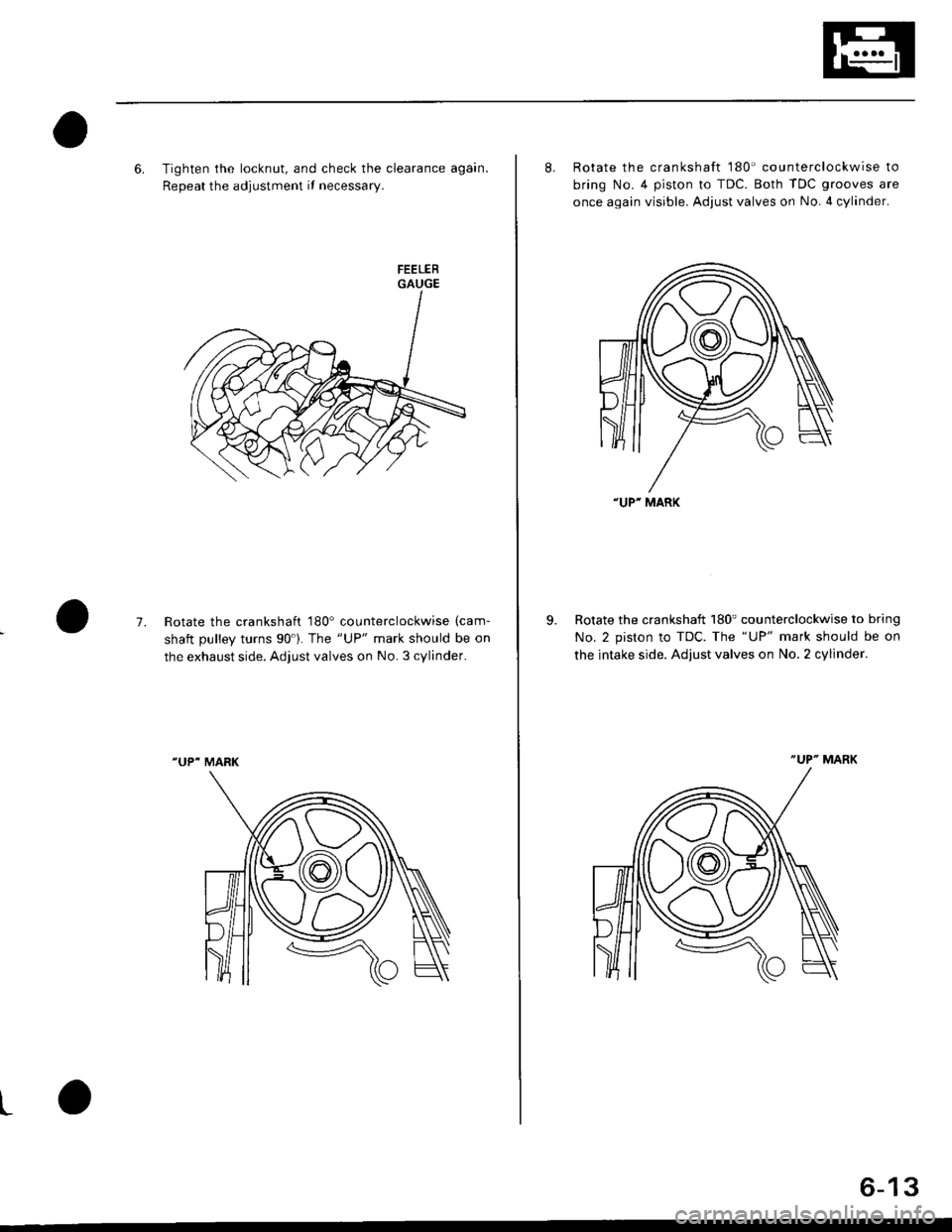
6. Tighten the locknut, and check the clearance again.
Repeat the adjustment if necessary.
GAUGE
7.Rotate the crankshaft 180' counterclockwise (cam-
shaft oullev turns 90'1. The "UP" mark should be on
the exhaust side. Adjust valves on No. 3 cylinder.
"UP- MARK
t
8. Rotate the crankshaft '180' counterclockwise to
bring No.4 piston to TDC. Both TDC grooves are
once again visible. Adjust valves on No. 4 cylinder.
Rotate the crankshaft 180'counterclockwise to bring
No. 2 piston to TDC. The "UP" mark should be on
the intake side. Adjust valves on No. 2 cylinder.
-UP'MARK
6-13
Page 138 of 2189
Removal
Engine removal is not required for this procedure
!!!s@ Make sure iacks and salety stands are
f ta"eata"ea propetty and hoist brackets are attached to the
correct positions on the engine.
CAUTION:
. Use tender covels to avoid damaging painted sul-
faces.
o To avoid damage, unplug the wiling connectors
carefully while holding the connector portion to
avoid damage.
. To avoid damaging the cylinder head, wait until the
engine coolant temperature drops below 100"F
{38"C} before loossning the tetaining bolts.
NOTE:
o Mark all wiring and hoses to avoid misconnectlon
Also, be sure that they do not contact other wiring or
hoses, or interfere with other parts.
. Inspect the timing belt before removing the cylinder
h ead.
. Turnthe crankshaft pu lley so that the No. lpistonisat
top dead center (see Page 6-21)
'1. Disconnect the negative terminal from the battery'
Drain the engine coolant (see page'10-7).
a Remove the radiator cap to speed draining.
Remove the intake air duct and air cleaner housing
(see page 5 3).
Remove the mounting bolt and lock bolt. then
remove the power steering (P/S) pump belt and
pump (see page 5'5).
Loosen the idler pulley center nut and adjusting
bolt' then remove the air conditioning (A'lc) com-
pressor belt (see Page 5-6).
Loosen the mounting nut and lock bolt. then
remove the alternator belt (see page 6-19).
Remove the P/S pump bracket (see page 5-12).
3.
4.
2.
6.
1.
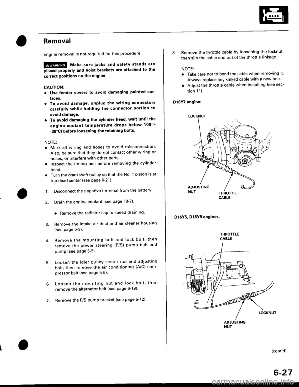
8. Remove the throttle cable by loosening the locknut,
then slip the cable end out of the throttle linkage
NOTE:
. Take care not to bend the cable when removing it
Always replace any kinked cable with a new one
. Adjust the throttle cable when installing (see sec-
tion 1 1).
D16Y7 engine:
Dl6Y5, Dl6Y8 engines:
THFOTTLECABLE
(cont'd)
6-27
LOCKNUT
CABLE
Page 160 of 2189
 07MAA - PR70100
g I ozvu,r - enu orzo
g")
Special Tools
(\
Ref. No. I Tool NumberDescriptionOty Page Relerence
q oTHAH PJ7010B
g I 07JAA-001020A
g I 07JAB-0010204
I 07JAB - 0010404
g 07LAJ - PR3020A
|6) 07MAA - PR70100
g I ozvu,r - enu orzo
g 07MAF - PR9010A
g 07742 - 0010100(!D I 07757-PJ10104
Valve Guide Reamer,5.5 mm
Socket, 19 mm
Holder Handle
Pulley Holder Attachment. 50 mm
Air Stopper
Tappet Adjuster
Tappet Locknut Wrench
Valve Spring Compressor Attachment ExtensionValve Guide Driver, 5.5 mm
Valve Spring Compressor Attachment
1 I 6-81
1 659
1 6-59
1 ] 6-5s
1 I 6-55
1 6-57
1 6-57
1 J 6-77
1 6-80, 81
1 6-71
ta;
aL)'n
-=<-,,LE;;
(D
a
6-50
\-
Page 167 of 2189
Valve Glearance
Adjustment
NOTE:
. Valves should be adjusted only when the cylinder
head temperaturs is less than 100'F (38'C)'
. After adjusting, retorque the crankshaft pulley bolt to
177 N.m (18.0 kgf'm, 130 lbt'ft)
1. Remove the cylinder head cover'
NOTE: Refer to page G86 when installing the cylin-
der head cover.
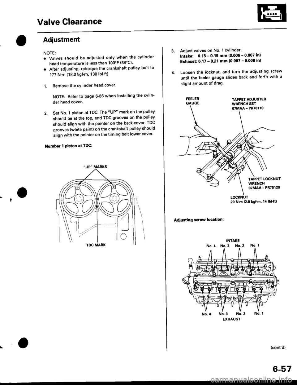
2. Set No. 1 pi$on at TDC. The "UP" mark on the pullsy
should be at the top, and TDC grooves on the pulley
should align with the pointer on the back cover' TDC
grooves {white paint) on the crankshaft pulley should
align with the pointer on the timing belt lower cover'
Number I Piston at TDC:
4.
Adjust valves on No. 1 cylinder.
lntako: 0.15 - 0.19 mm {0'006 - 0.007 in)
ExhaGt 0.17 - 0.21 mm {0'007 - 0 008 inl
Loosen the locknut, and turn the adjusting screw
until the feeler gauge slides back and forth with a
slight amount of drag.
TAPPET ADJUSTERWFENCH SET07MM - PR70110
TAPPET LOCKNUTWRENCH07MAA - PR70120
Adiusting sclaw location:
LOCKNUT20 N.m {2.0 kgf'm, lil lbt'ftl
(cont'd)
6-57
Page 168 of 2189
Valve Clearance
I
I
I
Adjustment {cont'd)
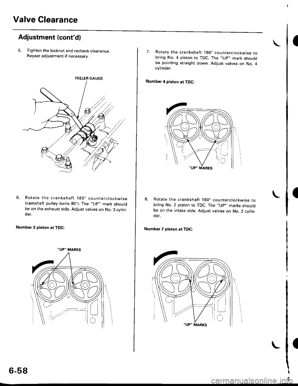
5. Tighten the locknut and recheck clearance.Repeat adjustment if necessary.
Rotate the crankshaft 180. counterclockwise(camshaft pulley turns 90'). The "Up" mark shouldbe on the exhaust side. Adjust valves on No. 3 cylin-der.
Number 3 piston at TDC:
FE€LER GAUGE
"UP- MARKS
6-58
7. Rotate the crankshaft '180. counterclockwise tobring No. 4 piston to TDC. The ,,Up,. mark shouldbe pointing straight down. Adjust valves on No. 4cylinder.
Number 4 piston at TDC:
8, Rotate the crankshaft 180. counterclockwise tobring No. 2 piston to TDC. The "Up., marks shouldbe on the intake side. Adjust valves on No. 2 cylin_der.
Number 2 piston at TDC:
L
Page 178 of 2189
Cylinder Head
Removal (cont'd)
8. Remove the P/S pump lower bracket.
8 x 1.25 mm24 N.m 12.4 kgf.m,17 tbtftl
9.
T SHIELD
10.
P/S PUMP LOWERBRACKET10 x 1.25 mm44 N.m {4.5 kgf.m,33 tbf.frl
Relieve fuel pressure (see section l1).
@ Do not smok6 while working on fuel
system, keep open flam€ or spark away lrom work
ar€a, Drain fuelonly into an approved cortain€r.
Remove the evaporative emission (EVAP) control
canister hose, fuel feed hose and breather hose.
BANJO BOLT33 N.m (3.4 kgl.m.25 lbf.ftl
BREATHERHOSE
WASHERS
6-68
\.
11. Remove the brake booster vacuum hose, fuel return
hose and vacuum hose (see page 5 4).
12. Remove the water bypass hose and positive crankcase
ventilation (PCV) hose.
WATER BYPASSHOSEWATER EYPASSHOSE
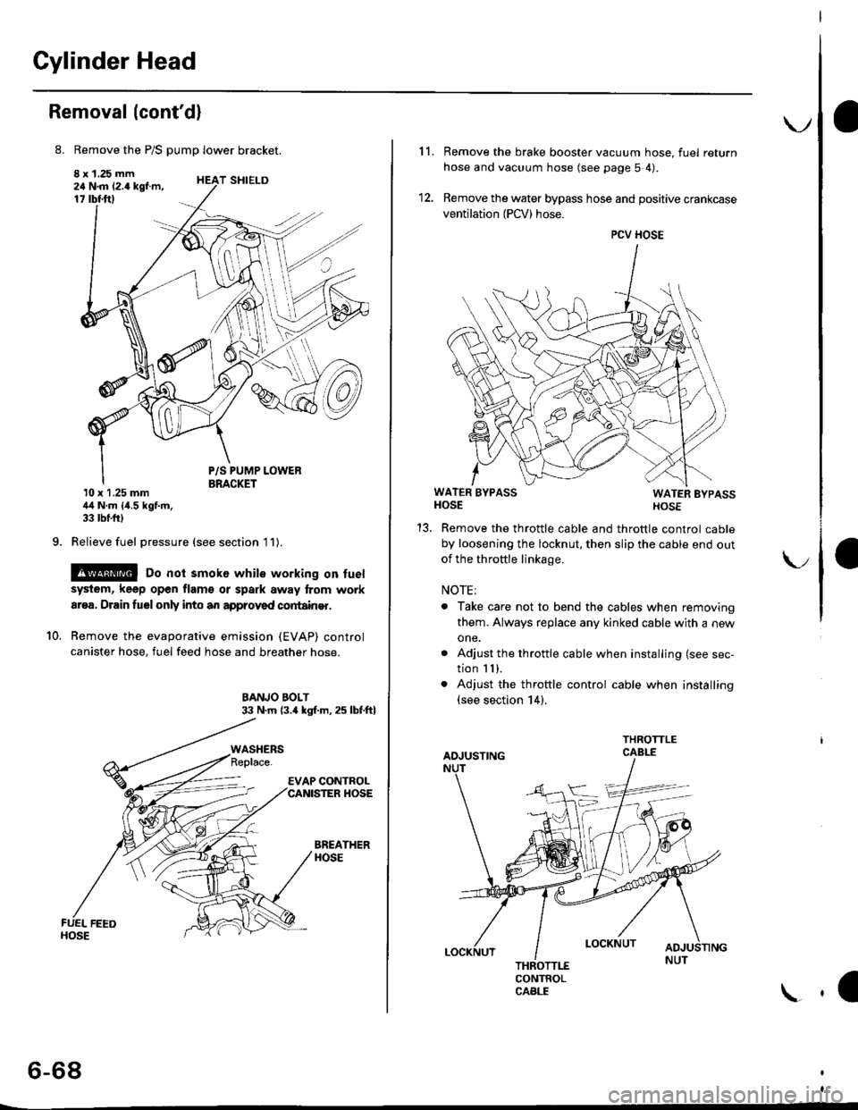
Remove the throttle cable and throttle control cable
by loosening the locknut, then slip the cable end out
of the throftle linkage.
NOTE;
. Take care not to bend the cables when removing
them. Always replace any kinked cable with a new
one.
. Adjust the throttle cable when installing (see sec-
tion I I ),. Adjust the throttle control cable when installing(see section 14).
CONTROLCABLE
1a
PCV HOSE
Page 193 of 2189
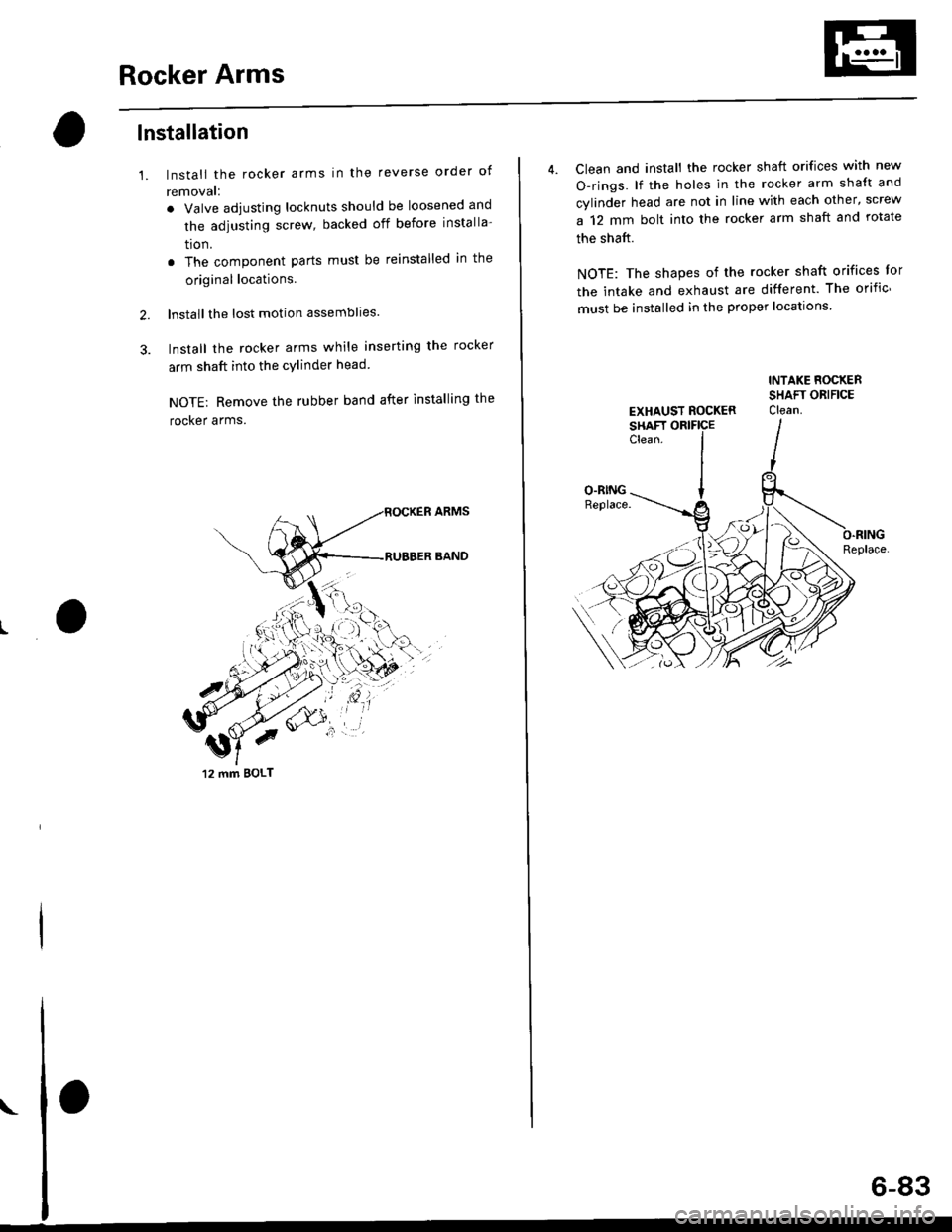
Rocker Arms
lnstallation
1.
2.
3.
lnstall the rocker arms in the reverse order of
removal:
. Valve adjusting locknuts should be loosened and
the adiusting screw, backed off before installa-
tron.
. The component parts must be reinstalled in the
original locations.
lnstall the lost motion assemblies.
lnstall the rocker arms while inserting the rocker
arm shaft into the cylinder head
NOTE: Remove the rubber band after installing the
rocker arms.
12 mm BOLT
\
6-83
4. Clean and install the rocker shaft orifices with new
O-rings. lf the holes in the rocker arm shaft and
cylinder head are not in line with each other, screw
a 12 mm bolt into the rocker arm shaft and rotate
the shaft.
NOTE: The shapes of the rocker shaft orifices tor
the intake and exhaust are different. The orific'
must be installed in the proper locations.
INTAKE ROCKER
SHAFT ORIFICE
EXHAUST ROCKER Clean
SHAFT ORIFICE
O.RING
O