light HONDA CIVIC 2000 6.G Workshop Manual
[x] Cancel search | Manufacturer: HONDA, Model Year: 2000, Model line: CIVIC, Model: HONDA CIVIC 2000 6.GPages: 2189, PDF Size: 69.39 MB
Page 1277 of 2189
t
\b
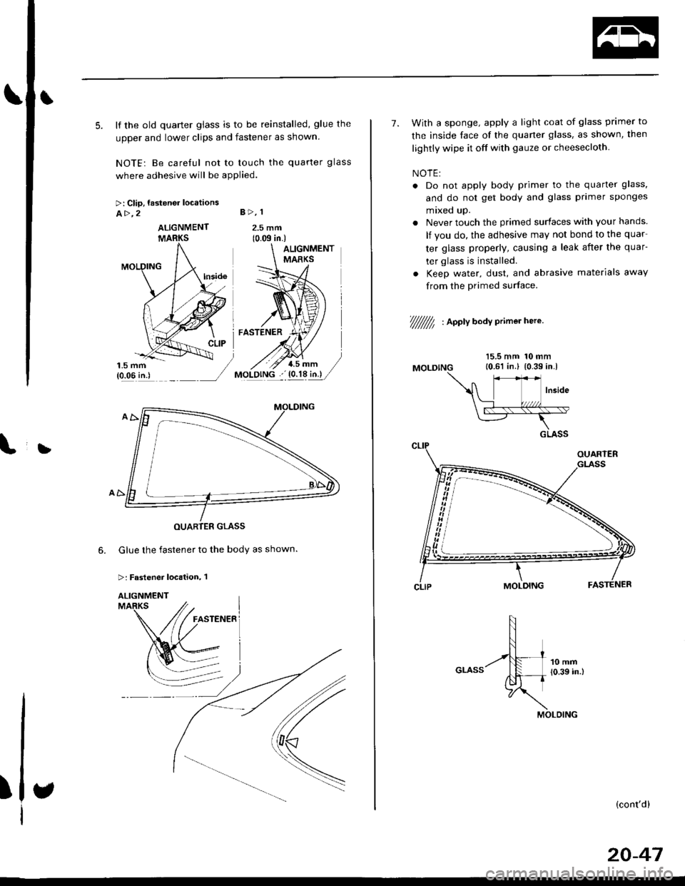
5. lf the old quarter glass is to be reinstalled, glue the
upper and lower clips and fastener as shown
NOTE: Be careful not to touch the quarter glass
where adhesive will be applied.
>: Clip, fastener locations
A>,2 B>, 1
2.5 mm(0.m in.)
Glue the fastener to the body as shown.
>: Fastener location, 1
6.
)
ALIGNMENT
7. With a sponge, apply a light coat of glass primer to
the inside face of the quaner glass, as shown, then
lightly wipe it off with gauze or cheesecloth
NOTE:
. Do not apply body primer to the quarter glass,
and do not get body and glass primer sponges
mixed up.
. Never touch the primed surfaces with your hands.
lf you do, the adhesive may not bond to the quar
ter glass properly, causing a leak after the quar-
ter glass is installed.
. Keep water, dust, and abrasive materials away
from the Primed surface
t///////7, , aootv a"av crimer here'
MOLDING
15.5 mm 10 mm10.61 in.l {0.39 in.l
(cont'dl
20-47
Page 1278 of 2189
Ouarter Glass
Installation (cont'dl
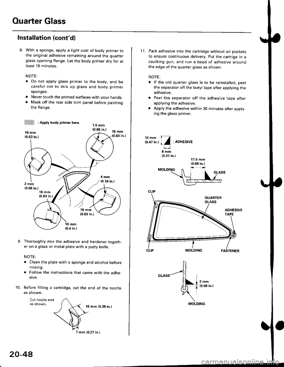
8. With a sponge, apply a light coat of body primer tothe original adhesive remaining around the quarter
glass opening flange. Let the body primer dry for atleast l0 minutes.
NOTE:
. Do not apply glass primer to the body, and becareful not to mix up glass and body primer
sponges.
. Never louch the primed surfaces with your hands.. Mask off the rear side trim panel before painting
the flange.
///ffi : Appty aoay primer here.
16 mm10.63 in.l
Thoroughly mix the adhesive and hardener togeth-er on a glass or metal plate with a putty knife.
NOTE:
. Clean the plate with a sponge and alcohol beforemixing.
. Follow the instructions that came with the adhe-sive.
Before filling a cartridge, cut the end of the nozzle
as shown.
Cul nozzle end
10 mrn (0.39 in.)
9.
10.
20-4A
7 mm 10.27 in.)
l'1. Pack adhesive into the canridge without air pockets
to ensure continuous delivery. Put the cartrige in a
caulking gun, and run a bead of adhesive around
the edge of the quarter glass as shown.
NOTE:
. lf the old quarter glass is to be reinstalled, peel
the separator off the butyl tape after applying theadhesive.
. Peel the separator off the adhesive tape afterapplying the adhesive.
. Apply the adhesive within 30 minutes after applying the glass primer.
12mm 11
lo.tt tn.l I l:ADHESIVE
8mm{0.31 in.)
CLIP
MOLDING
Page 1279 of 2189
}
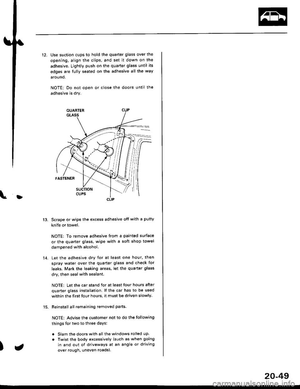
12. Use suction cups to hold the quarter glass over the
opening, align the clips, and set it down on the
adhesive. Lightly push on the quarter glass until its
edges are fully seated on the adhesive all the way
around.
NOTE: Do not open or close the doo.s until the
adhesive is dry.
Scrape or wipe the excess adhesive off with a putty
knife or towel,
NOTE: To remove adhesive from a painted surface
or the quaner glass, wipe with a soft shop towel
dampened with alcohol.
Let the adhesive dry for at least one hour, then
spray water over the quarter glass and check for
leaks. Mark the leaking areas, let the quarter glass
dry, then seal with sealant.
NOTE: Let the car stand for at least four hours after
quarter glass installation. lf the car has to be used
within the first four hours, it must be driven slowly
Reinstall all remaining removed parts-
NOTE: Advise the customer not to do the following
things for two to three days:
. Slam the doors with all the windows rolled up.
. Twist the body excessively (such as when going
in and out of driveways at an angle or driving
over rough, uneven roadsl.
13.
14.
)
CLIP
a
20-49
Page 1284 of 2189
Moonroof
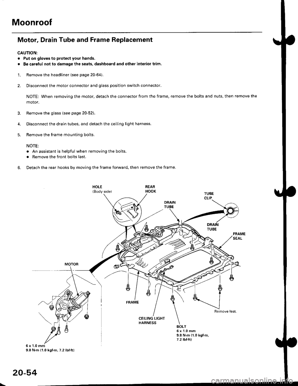
Motor, Drain Tube and Frame Replacement
CAUTION:
. Put on gloves to protecl your hands.
. Be careful not to damage the seats, dashboard and other interior trim.
'1. Remove the headliner {see page 20-64).
2. Disconnect the motor connector and glass position switch connector.
NOTE: When removing the motor, detach the connector from the frame, remove the bolts and nuts, then remove the
motor.
3. Remove the glass {see page 20-52).
4. Disconnect the drain tubes, and detach the ceiling light harness.
5. Remove the frame mounting bolts.
NOTE;
. An assistant is helpful when removing the bolts.
. Remove the front bolts last.
6. Detach the rear hooks by moving the frame forward, then remove the frame.
BOLT6x1.0mm9.8 N.m {1.0 kgt m,7.2 tht.hl
6x1.0mm9.8 N m (1.0 kgl.m, 7.2 lbtft)
20-54
\
Page 1291 of 2189
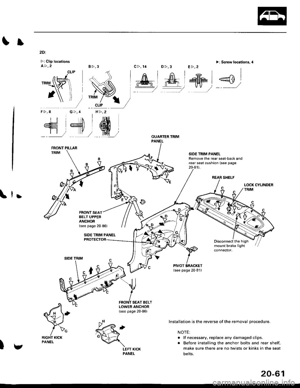
Il
2Di
>: Clip locationsa>,28>,3
CLIP
G>,4H >,2
D >,3>i Screw location3.4
REAR SHELF
SIOE TRIM PANELRemove the rear seat-back andrear seat cushaon (see page20-a1l.
,
Disconnect the highmount brake light
SEAT BELT
€'
/>"RIGHT KICKPANEL
)
TRIM
nJ'.'rI\ZI
1\f-
F>,8
N 4'dr
SIDE TRIM
LOWER ANCHOR(see page 20-86)
c>, 14E>,2
Installation is the reverse of the removal procedure.
NOTE:
. lf necessary, replace any damaged clips.
. Before installing the anchor bolts and rear shelf,
make sure there are no twists or kinks in the seat
belts.
FRONT PILLAR
FRONT SEATBELT UPPERANCHOR
v
.h,'t6d
\
LEFT KICKPANEL
20-61
Page 1294 of 2189
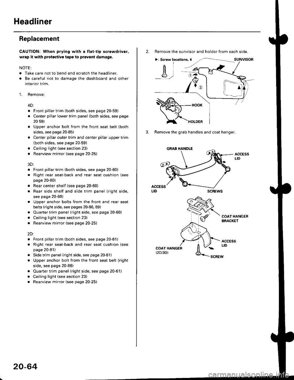
Headliner
Replacement
CAUTION: When prying with a flat-tip screwdriver,
wrap it with proioctiva tap€ to prevsnt damage.
NOTE:
. Take care not to bend and scratch the headliner.
. Be careful not to damage the dashboard and other
interior trim.
'1. Remove:
4D:
. Front pillar trim (both sides. see page 20-59)
. Center pillar lower trim panel (both sides, see page
20 59)
Upper anchor bolt from the front seat belt (both
sides, see page 20-85)
Center pillar outer trim and center pillar upper trim
(both sides, see page 20-59)
Ceiling light (see section 23)
Rearview mirror (see page 20-25)
a
a
a
a
a
3D:
. Front pillar trim (both sides, see page 20-60)
. Right rear seat-back and rear seat cushion (see
page 20-80)
. Rear center shelf (see page 20-60)
. Rear side shelf and side trim panel (right side,
see page 20-60)
. Upper anchor bolts from the front and rear seat
belts (right side. see pages 20-86, 89)
. Ouarter trim panel (right side, see page 20-60)
. Ceiling light (see section 23)
. Rearview mirror (see page 20-25)
2Dl
. Front pillar trim (both sides, see page 20-51)
. Right rear seat-back and rear seat cushion (see
page 20-81)
Side trim panel (right side, see page 20-61)
Upper anchor bolt from the front seat belt (right
side, see page 20-86)
Ouarter trim panel (right side, see page 20-6'l)
Ceiling light (see section 23)
Rearview mirror (see page 20-25)
20-64
2. Remove the sunvisor and holder from each side.
>: Screw locations,4
-A-,-
3. Remove the grab handles and coat hanger.
scREws
ACCESSLto
COAT HANGERBRACKET
ACCESSLIDCOAT HANGERt2D/3DlSCBEW
1^
Page 1299 of 2189
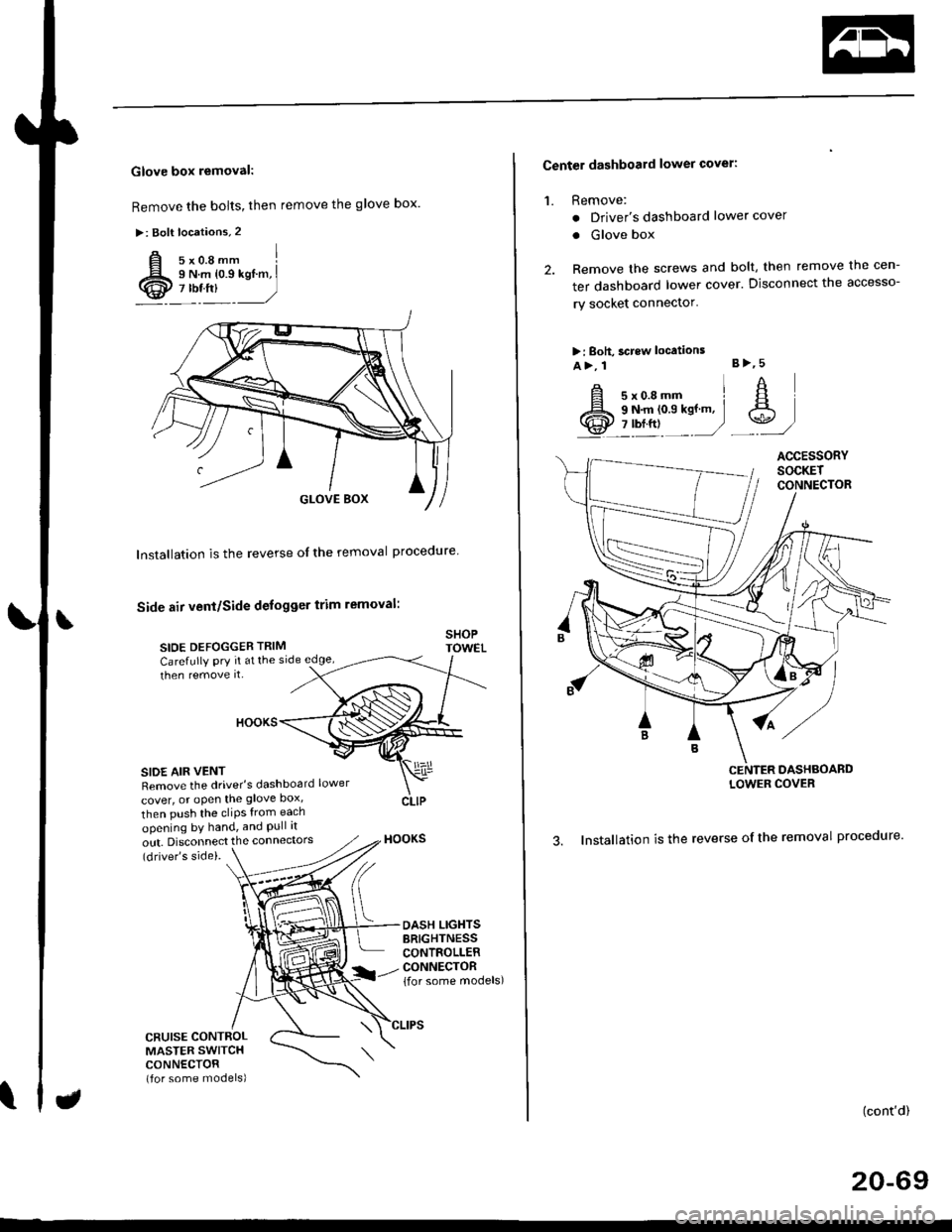
Glove box removal:
Remove the bolts, then remove the glove box.
>: Bolt locations,2
Installation is the reverse of the removal proceoure
Side air vent/Side defogger trim removal:
SIOE DEFOGGER TRIMSHOPTOWET_Carefully PrY rt at the
then remove it,side edge,
SIDE AIR VENTRemove the driver's dashboard lower
cover, or oPen the glove Dox,
HOOKS
then push the cliPs from each
opening by hand, and Pull it
out. Disconnect the connedors(driver's side).
HOOKS
DASH LIGHTSBRIGHTNESSCONTROLLERCONNECTOR{for some models)
CFUISE CONTROLMASTER SWITCHCONNECTOR(for some models)
Center dashboard lower covel:
1. Remove:
. Driver's dashboard lower cover
. Glove box
2. Remove the screws and bolt, then remove the cen-
ter dashboard lower cover. Disconnect the accesso-
ry socket connector'
>i Boh, screw locations
a>, 1 B>'5
A s*o.e-- I A
@;*;ry'-1'-.J _e)
3. Installation is the reverse of the removal proceoure'
(cont'd)
20-69
LOWER COVER
Page 1326 of 2189
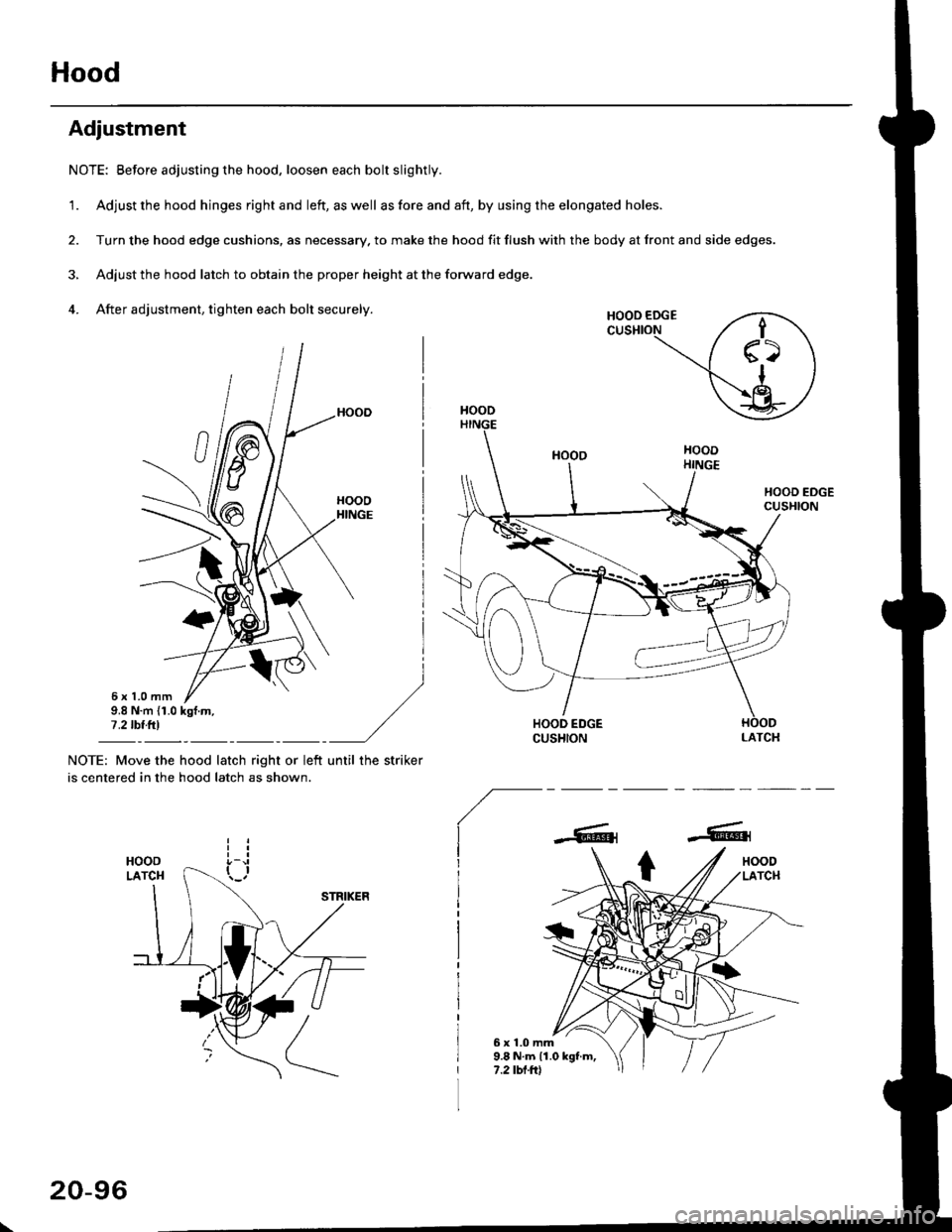
Hood
Adjustment
NOTE: Before adjusting the hood, loosen each bolt slightly.
1. Adjust the hood hinges right and left, as well as fore and aft, by using the elongated holes.
2. Turn the hood edge cushions, as necessary. to make the hood fit flush with the body at front and side edges.
3, Adjust the hood latch to obtain the proper height at the forward edge.
4. After adjustment, tighten each bolt securely.
6x1.0mm9.8 N.m {1.0 kgt.m,7.2 tbt.tll
NOTE: Move the hood latch right or left
is centered in the hood latch as shown.
)
until the striker
6x1.0mm9.8 N.m {1.0 kgf.m,7.2 tbf.ftl
\
20-96
Page 1327 of 2189
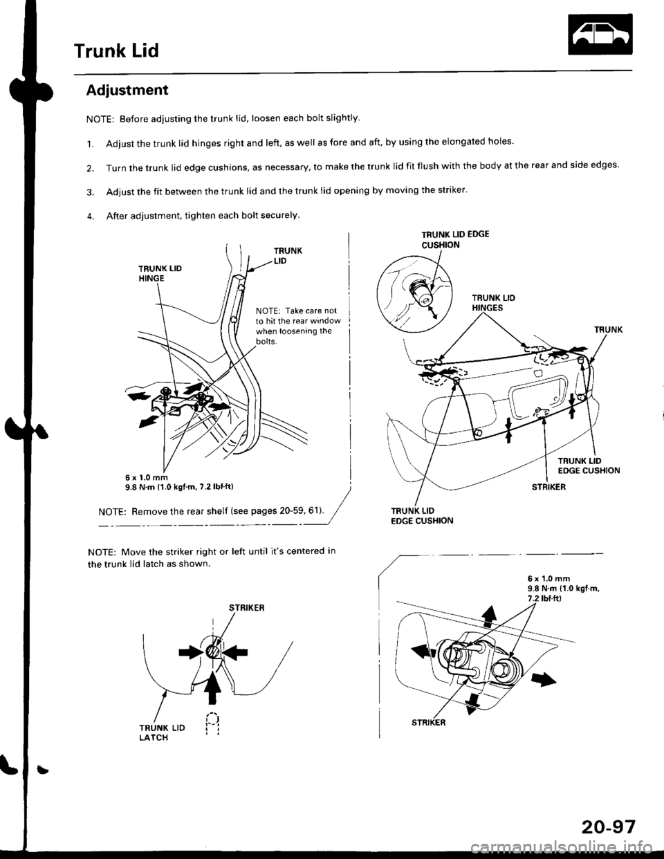
Trunk Lid
Adjustment
NOTE; Before adjusting the trunk lid, loosen each bolt slightly.
1. Adjust the trunk lid hinges right and left, as well as fore and aft, by using the elongated holes'
2. Turn the trunk lid edge cushions, as necessary, to make the trunk lid fit flush with the body at the rear and side edges.
3. Adiust the fit between the trunk lid and the trunk lid opening by moving the striker'
4. After adjustment, tighten each bolt securely
TRUNK LIO EDGE
CUSHION
TRUNK LID
NOTE: Take care notto hit the rear windowwhen loosening thebolts.
NOTE: Move the striker right or left until it's centered in
the trunk lid latch as shown.
TRUNK LIO
9.8 N.m {1.0 kgf.m,7 .2lbl.ltlSTRIKER
20-97
Page 1328 of 2189
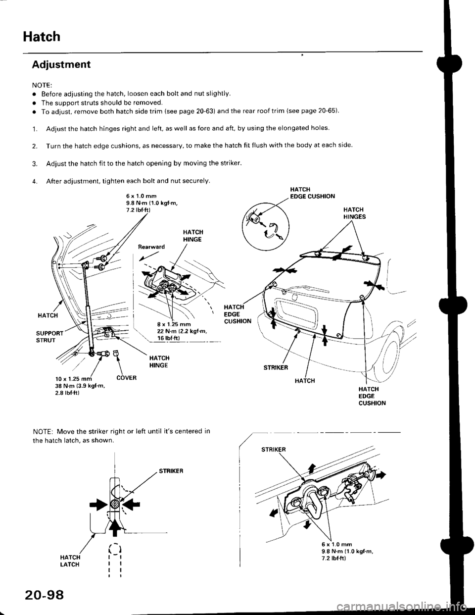
Hatch
Adjustment
NOTE:
. Before adjusting the hatch, loosen each bolt and nut slightly.
a The suDport struts should be removed.
. To adjust, remove both hatch sidetrim (see page 20-63) and the rear roof trim (see page 20-65).
1. Adjust the hatch hinges right and left, as well as fore and aft. by using the elongated holes
2. Turn the hatch edge cushions, as necessary, to make the hatch fit flush with the body at each side.
3. Adjust the hatch fit to the hatch opening by moving the striker.
4. After adiustment, tighten each bolt and nut securely.
6x1.0mm9.8 N.m (1.0 kgf.m,
HATCHEDGE CUSHION
HATCHHINGERearward
HAEDGECUSHION
j ... 22
\,_1q
N.m (2.2 kgf.m,tbf.ftl
\
co
38Nm(3.9kgfm,2.8 rbf.ft)
NOTE: Move the striker right or left until it's centered in
the hatch latch. as shown.
HATCHHINGESTRIKER
l0x1VER
HATCHEDGECUSHION
9.8 N.m 11.0 kst.m,7.2 tbf.ft)HATCHLATCH
20-98
6x1.0mm