tow HONDA CIVIC 2000 6.G Owner's Manual
[x] Cancel search | Manufacturer: HONDA, Model Year: 2000, Model line: CIVIC, Model: HONDA CIVIC 2000 6.GPages: 2189, PDF Size: 69.39 MB
Page 357 of 2189
Troubleshooting
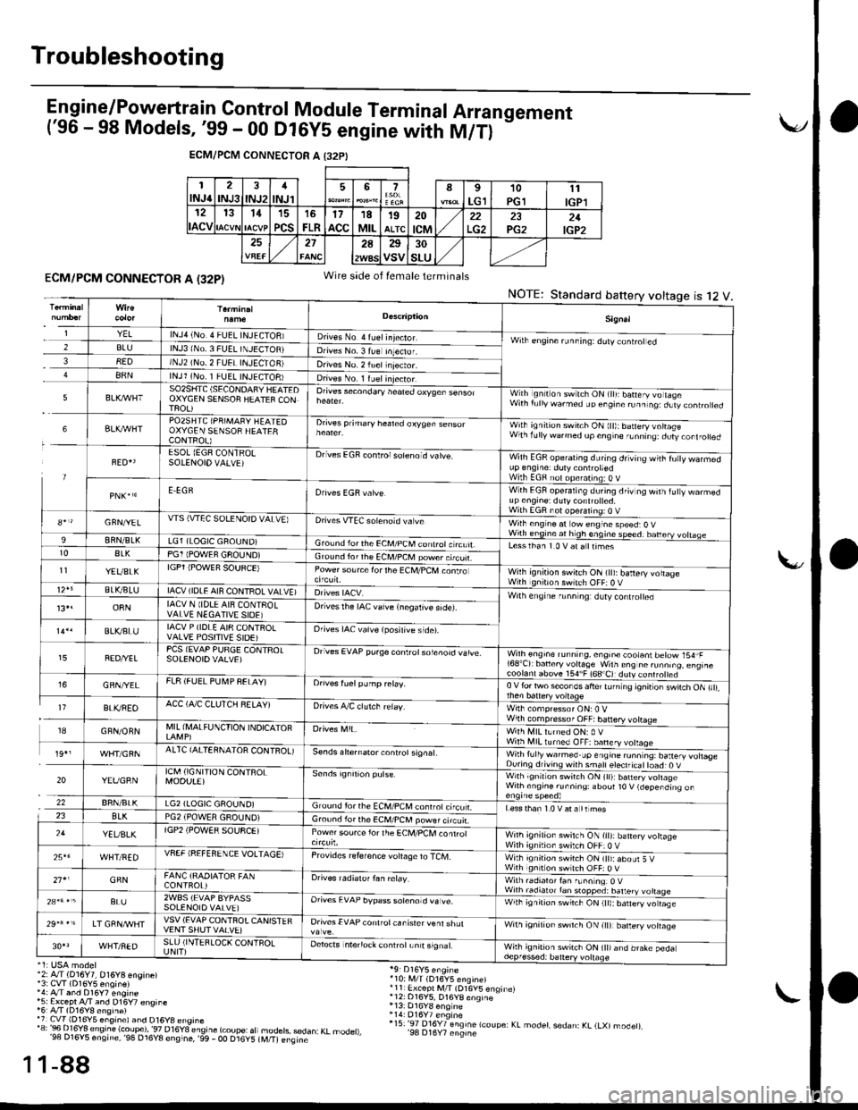
E n gine/P_o,weft ra in Control Module Term inal Arra n gement('96 - 98 Models, '99 - 00 Dl6yS engine with M/T)
-
ECM/PCM CONNECTOR A I32PI
1INJ62INJ3INJ21
INJl567I
LG110PGll1
IGPl12
ACV
131115
PCS
16
FLR17acc18MIL19ALTC20
tcM22PG221IGP2272A25
VSV30
SLU
ECM/PCM CONNECTOR A (32P)
'2: A./T (D16Y7, 016Y8 engine)13: CvT (D16Y5 enoin€)',4: A/T and D16y7 engine*5: Except A/T and D16Y7 €nsine'6r A/T (D16Y8 ensine)'7 Cw 1D16Y5 eng,nel and D16y8 ensrne'"'3:Bi..I?'Jt;".'e'.!ti.?i?l'""."T8"_";btfr
"fl
1-88
Wire side of female terminals
NOTE:Standard battery voltage12ts
'10i i,4/T (D16V5 engine)r11 Ex.ept M/l (D16V5 enqinelr12: 016Y5, D16YB enqine
r15:'97 016Y7 engine lcoupe: KL modet, sedan: KL (LXl modet),'98 D16Y7 engine
1
1
Sign.l
YELlNJ4 (No.4 FUEL INJECIOB)D ves No 4 ruel injector.Wilh engine runninq: ddly coniroted2BLUlNJ3 lNo. 3 FUEL TNJECTOBJDrives No. 3 lue Inteclor.38EDINJ2 (NO, 2 FUEI INJECTON)Drives No. 2 iuel njector.88NlNJl (No. 1 FUEL INJECTOB)Dives No. 1 ruelinjector.
5SO2SIITC (SECONDAFY HEATEDOXYGEN SENSOF HEATEF CONTFOL)
Orives secondary heated oxyqen sensorWith ignilion switch ON (lll: batery vo lageWith f!llywarmed up engine runninq:dLtv controled
6BLXAVHTPO2SHTC (PRIMAFY HEATEOOXYGEN SENSOR HEATERCONTROL)
Drives prihary healed oxygen sensorWith ignition switch ON ltt):baneryvottasewlhrdllywdrmedupcngne,Lnnrrq dury,orl.otred
FED{ESOL (EGF CONTRO!SOIENOIO VALVE)Drives EGF conlrolsoleno d vatve.Wilh EGR operating during drving wiih fu|y warmedup engrne: duty controttedWilh EGF nol opefating:O VE.EGRWith EGF operating du.ing driv og wilh iuty warmedup en9ine: dutycont.olted.With EGR not ooeralino; o V8*r/GFN/YELWS (VTEC SOLENOTD VALVE)Drives VTEC solenoid va veWilh eng ne at ow engine speed:O VWirh engine at h gh enqine speedr banery vohaae9BflN/BLKLG1 (LOGIC GROUND)Gro!nd lorthe €CM/PCM conlrotc rcuit.Lesslhan 1.0 V at a ttimest0ALKPG1 IPOWEF GFOUND)Ground ior rhe ECM/PCM power.tcuf.11YEVBLKIGPT iPOWEF SOUFCE)Power source forthe Ec[,l/PcM conlroWilh ignition swirch ON (tt): battery voltageWith gntron switch OFF: 0 VBLVBLUIACV (IDLE AIN CONTROL VALVE)Wilh engine r!nn ng: dlty contro ed13,.o8NIACV N lIDLE AI8 CONTFOLVALVE NEGATIVE SIOE)Drivesthe IAC valve {negalive side).
BLVBLUIACV P (IDLE AI8 CQNTROLVALVE POSITIVE SIDE)Orives IAC vaive (posilive side).
FEO/YELPCS (EVAP PURGE CONTFOTSOIENOIOVALVE)Drives EVAP pu.ge controtsolenoid vatve.Wilh engioe running, engin€ cootani betow 154,F'68'Cr bancry vohaSe w'ln ens nc runn,.o. eng,rc
GRN/YELFL8 (FUEL PU[4P FELAY)Orives fuelpump relay.0 V {or two secor os ahe' tJ n ng 'onir or \wnch ON ,,,,,
I7BLI(REOACC (A,/C CLUTCH RELAY)Drives A/C clutch relay.Wirh compressor ONr0 VWilh compressof OFF:banery votrage18GFN/ONNMIL (I\,lALFUNCTION INDICATOFWith MIL lLrned ON: 0 VWith illl turned OFF: banery volaqe19',AITC {AITERNAIOR CONIROL)se.ds ahernator controt signat.Wirh fully warmed.up engine ru.ntng: battery votlas€During drivins wnh smatl eteclricat toad: O V
20YEVGRNICM (IGNI'TION CONTROLMOOU!E)with ignltlon swilch ON (tl):b6n€ry vohageWilh ensine runnins: aboul t0 V (depending on
22BRN/BLKLG2 (LOGIC GAOUND)Ground for the ECM,/PCM conrrot ci'cu LLess than 1.0 V at a tt mes23BLKPG2 iPOWEA GROUND)Gro!nd lor the ECM/PCM power circuir.24YEUBLKlGP2 (POW€R SOUSCE)Power sou.ce lor the ECM/PCl, conrrolWnh ignilion swilch ON {it):battery vohageWilh ignilion switch OFF:0 V25*6WHT/FEDVSEF IREFEfl ENCE VOLTAGE)Provrdes reference voIaOe to TCM.With ignition switch ON (tt):abour 5 VWth gnition swltch OFF: O V21'1GFNFANC {RAOIATOR FANCONTFOL)Drives radialof fan ielay.With radialor fan f!nn nqr O VWilh radiato.tan stopped: batteryBL!2WBS (EVAP BYPASSSOLENOIO VALVE]Orives EVAP bypass sotenotd va !e.With ignirion swrrch ON (tt):barery vo rase
LT GRNA/VHTVSV (EVAP CONTFOTCANISTEFVENT SHUT VAIVE)Drives EVAP conlfot canisrer venl shulwnh ignirion sw'tch ON lr|l barery volaqe
WHT/NEDSLU (INTEFLOCK CONTFOLUNIT)Detects intenock conlrotLn t signalWhh ignition switch ON (tt)and brake pedadepf essed: battery vollage
Page 361 of 2189
Troubleshooting
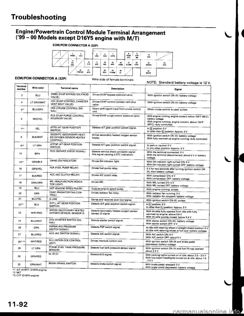
Engine/P_o,wertrain Control Module Terminal Arrangement('99 - 00 Models except Dl6Y5 engine with M/Tl
ECM/PCM CONNECTOR A (32P)Wire side ot temale terminalsNOTE:Standard battery voltage is l2 V
ECM/PCM CONNECTOR A I32PI
Sign!l
3BLU2WSS (EVAP 8YPAsS SOLENOIDDrives EVAP bypass solenoid vatve,With gn'tion swnch ON (lll banery votlage
LT GRN/I/VIITVSV {EVAP CONTNOL CANISTERVENTSHUTVALVE]Drives EVAP controt ca n isrer v€nt shutWilh ignilion switch ON {tl): b€ttery vottage
8LU/GNNC8S (CRUISE CONTSOL SIGOown shift signal inpot lrom c.uise conrrolWhen crurss control is used:purses
68ED/YELPCS {EVAP PURGE CONTROLSOTENOIOVALVE)Drives EVAP purge conrrol sotenoid vatve.With engine running, engine cootant, betow r54.F (6a,C):
With engine.unning, €ngine coolant, abov€ 154.F(68'C): duty conlrolled
YELATPD {AT GEAR POSITIONSWITCH)ootects A/T gear posnion swilch s,gnar.In otherthan @ posilion: Apprcx. 5 V
8BLK,IflHTSO2SHTC (SECONDARY HEATED OXYGEN SENSOS HEATEFCONTFOL)
Drives sscondary h€ared oxygen senso.Wilh isn,rion swirch ON (ll):banery votraseWith lully warm6d dp€ngire runn'ng:dury controled
LT GRNATPNP (AT GEAF POSITIONSWITCH)oereds A/T 9€a r position switch signat.In Parr or neulrsl:0 VIn anyother position approx.5 v
t088NSCS (SERVICE CHECK SIGNAL)Oetects ssruice check connecror signal(the signalcausing a OTC indication)with rh€ t6rminal connected: 0 vWith the rerm ina I disconneded: abour 5 V of ban€ry
GNN/BIKD4IND (D4INDICATON]Drives Oa indicaio. lighr.With D4 indicator lightturned ON: O VWith D4 indicator lightturned OFF: battery vo ttageG8N/YETFTF (FUEL PUI\,4P SELAY)Orivos tuel pump relay,0V for two s€conds lfrer turnrng rgnilior swtcn ON(ll), then batt€ry voltage11BTI(REDACC (Al/C CTUTCH SELAY)Drives A./C clutch reray.With compressor ON:O VWilh comp.ssor OFF; battery vottage18GFN/OFNMI! (A,IAIFUNCTION INDICA.TOF LIGHT)With MlLturned ON:0 VWith l\,llL tornod OFF|batrery votrsge198tuNEP (ENGINE SPEED PUTSEIOulputs6ngine speed pulse,Wilh engin6.unning: putses
20GFNFANC {SADIATOR FAN CONTnoL)Orives radiarortan relay.Wirh r.distor t6n running:OVWith radiatortan stopped: banery vottage21ELUA/ELK LINESends and r€ceives s.an lool signal.With ignition switch ON (ll):p!ts€s
22'lBLUATP L {AT GEAS POSITIONswtTcH)Oelocis A"/T gear posirion switch siSnat.In othfflhan E position: Apprcx. 5 V
23SHO25 (SECONOARY HEATEDOXYCEN SENSOR, SENSOF 2)Detects secondsry hoar€d oxygen sensorWith lhronle f! lly or'6ned from idte with fu ywarmod up engine: above 0.6 vWiih th.onl6 quickb, closd:below 0,4 V24STS ISTAFTEN SWITCH SIGDebcrs staner switch signat.Wirh srarterswitch ON (tttJ: batteryvottogeWith sraftsr cwirch OFF:0 V26GFNPSPSW iPlS PNESSURESWITCII SIGNAL)Derecrs PSP switch signat.Atidle with steoring wheolin srraightahead position: O VAt idl6with steering wheetal fult lock: barery vo ttags27BLU/REOACS (AJC SWITCH SIGNALJOer*ts ,ay'C swirch signat.Wiih ty'C switch ON;0VWilh Ay'C switch OFF|aboor 5VWHT/REDSLU iINTERLOCK CONTROIUNIT)Drivos interloct control unit.With ignltion switch ON (ll)and brake pedaldepresed: batlory volrage29LT GRNPTANK (FUEL TANK PFESSUEESENSOR)Oer6ds lu€l tank pr€ssura sonsor signat.Wilh ig.rrrd swirch ON rttr and fuetti
cap ooen6d.
30GRN/FEOEr (ELOIWith parking lighlsrurned on ar idteiaboui 2.5- 3.S VWirh low beam he€dlig hts turnqd on ai idts: aboul 1.52.5 V32GRN/'WHTAKSW (BFAKE SWITCH)Detets brak€ swrtch signEt,With brake pedal r6l€ased:0 VWhh brake pedaldepres*d: battery voltEse'1:A./T (D16Y7, D16Y8 engine)*2: rvt/T13: CVT (D16Y5 engine)
11-92
Page 363 of 2189
Troubleshooting
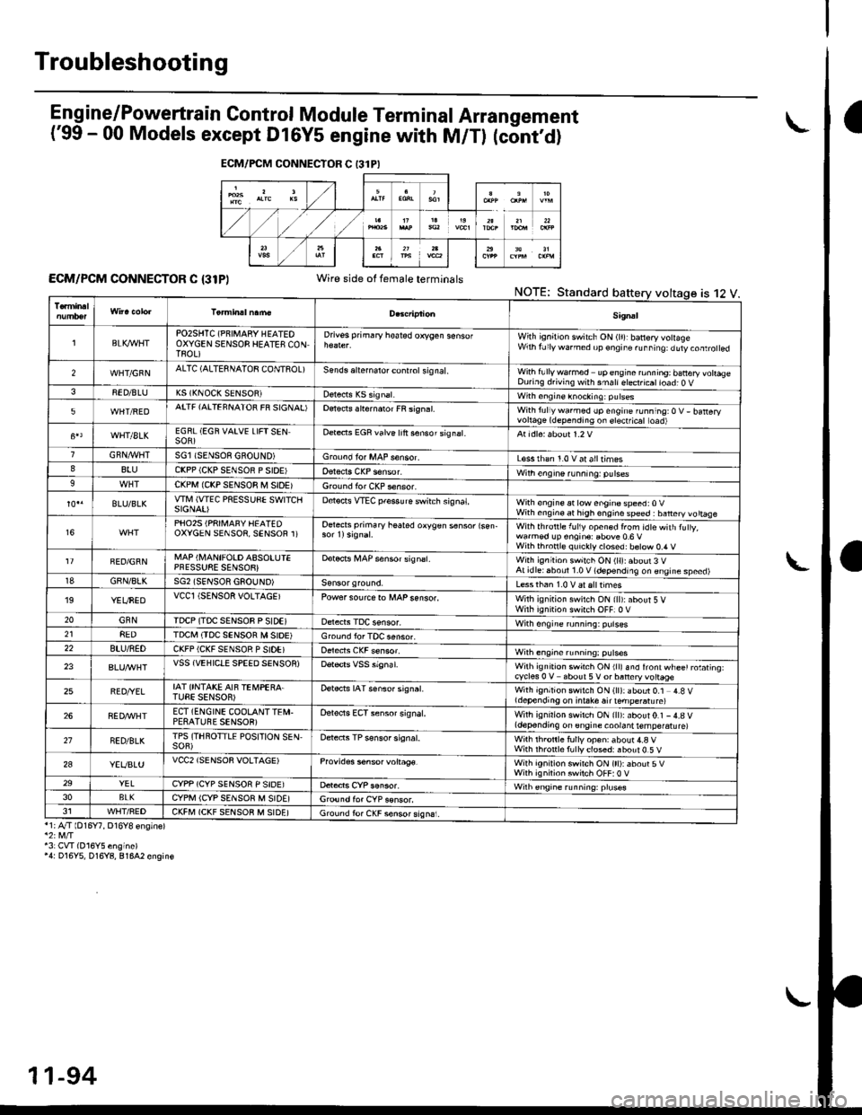
Eng ine/P_owertrain Control Module Term inal Arrangement
('99 - 00 Models except Dl6Y5 engine with M/Tl (cont,d)
ECM/PCM CONNECTOR C {31P)Wire side of female terminalsNOTE;Standard
*1;4"/T lD16Y7, D16Y8 ensinel
43: CVI(016Y5 engine)'4: D16Y5, D16Y8, 81642 engin€
ECM/FCM CONNECTOR C 13lPI
is 12 V.
Sig.al
lBLK4/VHTPO2SHTC (PNIMARY HEATEOOXYGEN SENSOB HEATES CONTROL)
Drivss primary hoated orygen sensofWith ignition switch ON (lr)rbanery volageWrh fJly warned up €ngir. ru..i19: duty.oaro ed
2WHT/GFNALTC (ALTESNATOB CONTSOL)Sends aliernalo. control sig nal,With fullywa.med upengine ronning; banery vohaseDuring d.iving with smallelect.icatioad; O V38ED/BLUK5 (KNOCK SENSOR)with sngine knocking: pulses
5WHT/REDATTF {AITEFNATOR FR SIGNAL'Detects slternaror FR si9n.l.With tullywarmed up engine running:O V- batteryvortage(dependingon erectficat toad)
WHT/8LKEGRL (EGN VAIVE LIFTSENSOR)Dete.ts EGR valve lrft sensorsignat.
GRN,4r'l/flTSGl ISENSOE GBOUND)Groond fo. MAP s€nsor.L€ss rhan 1.0 v at alltimes88luCKPP (CKP SENSOR P SIOE'With engine running: pulses9CKPM {CKP SENSOR M SIDEIGround for CKP sensor.
BLU/BLKwlvl (wEc PREssuSE swtTcllSIGNAI)D€tocts VTEC pfessure switch signat,With €ngine at low enginospeed:0VWith engin€ at high engino speed : banery vo ttaae
16PHO25 (PRII\,1AFY HEATEDOXYGEN SENSOR, SENSOR 1)Oetects primary heated oxygen s6nsor lsen-With lhrottle f!l1y open€d from idtewith tuly,wa.med !p engin€: Ebove 0.6 VWilh thronl€ quickly closed: b€tow 0.4 V
FED/GRNMAP (I\,4ANIFOLD ASSOLUIEPFESSUSE SENSOB}Dotocrs i,4AP sensor signsl.With ignitioh switch ON (ll):about 3 VAt idlei6boul 1.0 V (depending on engine speed)18GBN/8LKSG2 (SENSOR GSOUND)Less than 1.0 V aralttimes'19YEUNEDVCCl (SENSOR VOLTAGEIPowersourcero MAPsenso..With ignition swilch ON {ll):about 5 VWirh iqnition switch OFF]0 V20GNNIDCP (TDC SENSOB P SIDEIWith ongine running: pulses218EDTDCI\,I (TDC SENSOR M SIOE)Ground lor TOC aensor.22BTU/NEDCKFP (CKF SENSOR P SIDE)With engine running: p!lses
23VSS {VEHIClE SPEED SENSOR)Wilh ignrt|on swich ON rllr snd lront wl-ee' rotating.cycles 0 V about 5V or baneryvottage
25BED/YELIAT ONTAKE AIF TEi,4PEBA.TUEE SENSOR)Detects IAT senso. signat.With ignition switch ON (ll): about 0.1 4.8 Vldepending on i.take air ternpe.atu re)
268ED,ryVHTECT (ENGINE COOLANTTEI\,I.PESATUBE SENSOR)Oelects ECT sensor signal.With ignirion swirch ON {ll):about0.1 -4.8 V(depending on engine coolant temperatu re)
21NED/BLKTPS (THROTTLE POSITION SEN,SOF)Detects TP sensor signal.Wilh th.onle fully op€n: about 4.a VWith rhronle f!lly closed: about 0.5 V
2aYEVBLUVCC2 (SENSOR VOLTAGE)Provides s6nsor voltag€.With ignirion swirch ON (tt):about 5VWith ignilion swiich OFF:0 V29YELCYPP (CYP SENSOR P SIDE)Wilh €ngrne running: pruses3oBLKCYPM (CYP SENSOR M SIDE]G,ound for CYP sonsor.J1WHT/FEDCKFM (CKF SENSOB M SIDE)Ground fo. CKF sonsorsign6i.
11-94
Page 397 of 2189
PGM-FI System
Engine Coolant Temperature (ECTI Sensor
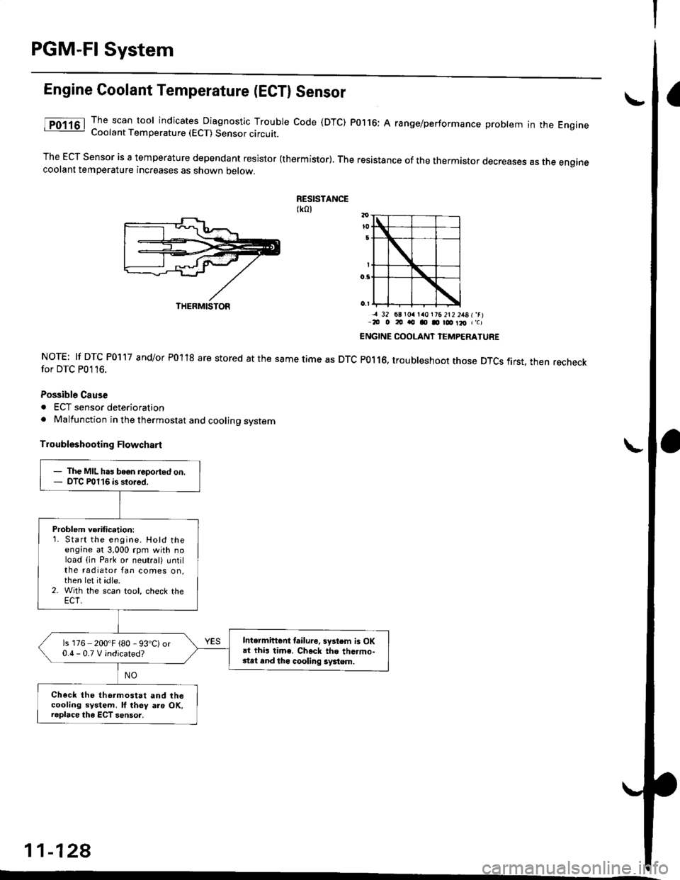
The scan tool indicates Diagnostic Trouble code (DTC) P0116; A range/performance problem in the EngrneCoolant Temperature (ECT) Sensor circuit.
The ECT Sensor is a temperature dependant resistor (thermistor). The resistance of the thermistor decreases as the enginecoolant temperature increases as shown oetow.
RESISTANCE(ko)
NOTE: lf DTC P0117 and/or P01'18 are stored at the same time as DTCfor DTC P0116.
Possible Cause
. ECT sensor deterioration. Malfunction in the thermostat and cooling system
Troubleshooting Flowchart
-a 32 68 r0a la0l?6 2t2 2481'rr-20 o 20 ao o D r@ Il, r'c)
ENGINE COOLANT IEMPERATURE
P0116, troubleshoot those DTCS first. then recheck
11-128
THERMISTOR
- The MIL has bogn reported on.- DTC P0116 is stored.
Problem verification:1. Start the engine. Hotd theengine at 3,000 rpm with noload (in Park or neutral) untilthe radiator fan comes on,then let it idle.2. With the scan tool, check the
Intermiftent lailure. system is OKai thi. time. Ch.ck the thc.mo-stat 6nd thc cooling system.
is 176 200'F {80 - 93'C)or0.0-0.TVindicated?
Check the thermostat and thecooling system. ll they als OK,raplace the ECT sensor.
Page 460 of 2189
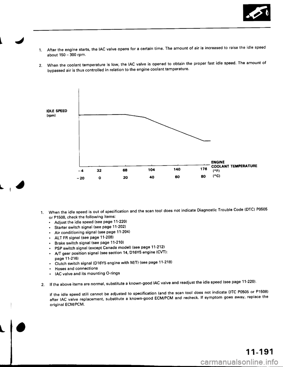
1.After the engine starts, the lAc valve opens for a certain time. The amount of air is increased to raise the idle speed
about 150 - 300 rpm.
When the coolant temperature is tow, the IAC valve is opened to obtain the proper fast idle speed. The amount of
bypassed air is thus controlled in relation to the engine coolant temperature'
IOLE SPEED
lrpml
176
80
ENGI ECOOLANI TEMPERATURE
t" Fl
toc)
ll
't.Whentheid|espeedisoutofspeciiicationandthescantoo|doesnotindicateDiagnosticTroub|ecode(DTc)P0505
or P1508. check the following items:
. Adiust the idle speed {see page 11-220}
. Starter switch signal (see page 11-202)
. Air conditioning signal (see page l1-204)
. ALT FR signal (see Page 11-2081
' Brake switch signal (see page 11-210)
. PSP switch signal (excapt Canada model) (see page 11-212)
. A,/T gear position signal {see section 14, Dl6Y5 engine (CVT):
page 11-216). Clutch switch signal (D16Y5 engine with M/T) (see page 11-218)
. Hoses and connections
' IAC valve and its mounting O-rings
lf the above items are normal, substitute a known-good IAC valve and readjust the idle speed (see page 11-220)
|ftheid|espeedsti||cannotbeadjustedtospecification(andthescantoo|doesnotindicateDTcP0505orP]50S)
after IAC valve replacement. substitute a known-good ECM/PCM and recheck. lf symptom goes away, replace the
original ECM/PCM.
Page 496 of 2189
I
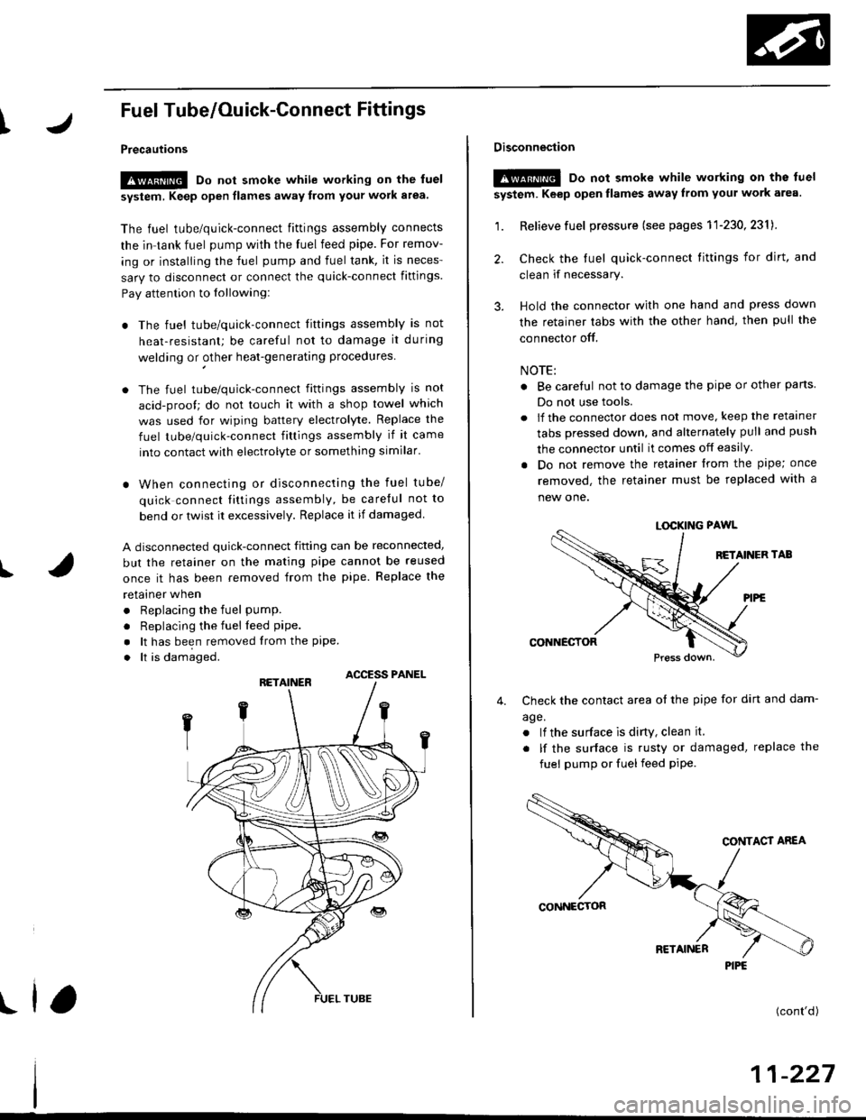
Fuel Tube/Ouick-Gonnect Fittings
Precautions
!@ Do not smoke while working on the fuel
system, Keep open flames away from your work a.ea'
The fuel tube/quick-connect fittings assembly connects
the in tank fuel pump with the fuel feed pipe. For remov-
ing or installing the fuel pump and fuel tank, it is neces-
sary to disconnect or connect the quick-connect fittings.
Pay attention to lollowing:
. The fuel tube/quick-connect fittings assembly is not
heat-resistant; be careful not to damage it during
welding or other heat-generating procedures
. The fuel tube/quick-connect fittings assembly is not
acid-proof; do not touch it with a shop towel which
was used for wiping battery electrolyte. Replace the
fuel tube/quick-connect fitlings assembly if it came
into contact with electrolyte or something similar.
. When connecting or disconnecting the fuel tube/
quick connect liltings assembly, be careful not to
bend or twist it excessively. Replace it if damaged
A disconnected quick-connect fitting can be reconnecled,
but the retainer on the mating pipe cannot be reused
once it has been removed from the pipe. Replace the
retatner wnen
. Replacing the fuel pump.
. Replacing the fuel leed pipe.
. lt has been removed lrom the PiPe.. lt is damaged.
ACCESS PANEL
I
Disconnestion
!@ Do not smoke while working on the luel
system. Keep open llames away lrom youl work area.
1. Relieve fuel pressure (see pages 11'230,2311.
2. Check the tuel quick-connect tittings for dirt, and
clean if necessary.
3. Hold the connector with one hand and press down
the retainer tabs with the other hand, then pull the
connector off.
NOTE:
o Be carelul not to damage the pipe or other pans
Do not use tools.
. lf the connector does not move, keep the retainer
tabs pressed down, and alternately pull and push
the connector until it comes off easily.
. Do not remove the retainer from the pape; once
removed, the retainer must be replaced with a
new one.
LOCKING PAWL
BETAINER TAB
CONNECTOR
Check the contact area o{ the pipe for dirt and dam-
age.
. lf the surface ls dirty, clean it.
. lf the surface is rusty or damaged, replace the
fuel pump or fuel feed piPe.
4.
(cont'd)
11-227
PIPE
Page 499 of 2189
Fuel Supply System
System Description
The fuel supply system consists of a fuel tank, in-tank
high pressure fuel pump, PGM-FI main relay, fuelfilter,
fuel pressure regulator, fuel injectors. and fuel delivery
and return lines. This system delivers pressure-regu-
lated fuel to the fuel injectors and cuts the fuel delivery
when the engine is not running.
Fuel Pressure l'96 Modelsl
Relieving
Before disconnecting fuel pipes or hoses, release pres-
sure from the system by loosening the 6 mm service
bolt on top of the fuel filter.
. Do not smoke whil6 working on the fuel system.
Kgsp opon flames or sparks away from youl work
area.
. Be sure to relieve fuel pressure while the ignition
switch is off.
1. Write down the frequencies for the radio's preset
buttons.
2. Disconnect the battery negative cable from the bat-
tery negative terminal.
3. Remove the fuelfill cap,
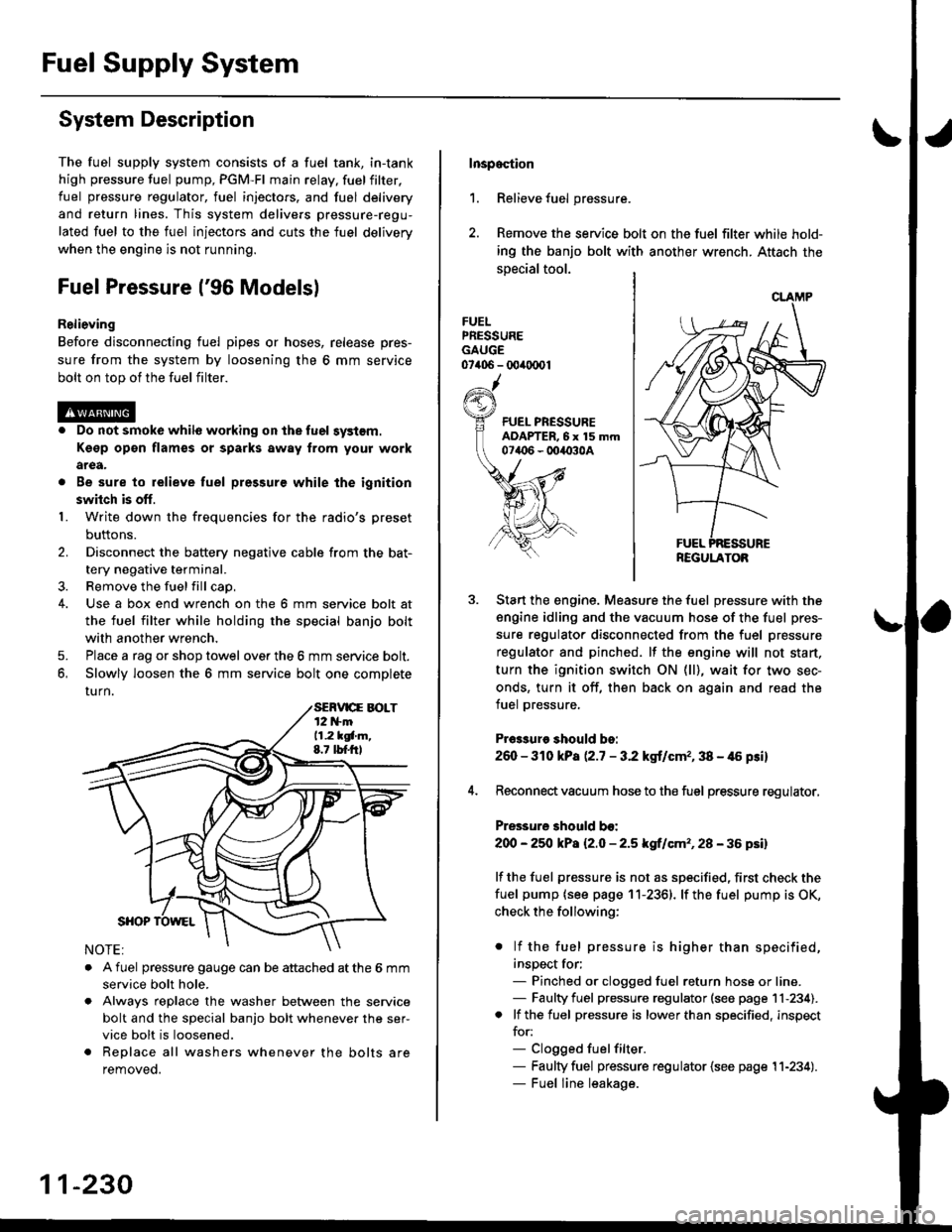
4. Use a box end wrench on the 6 mm service bolt at
the fuel filter while holding the special banjo bolt
with another wrench,
5. Place a rag or shop towel over the 6 mm service bolt.
6, Slowly loosen the 6 mm service bolt one complete
rurn.
. A fuel pressure gauge can be attached at the 6 mm
service bolt hole.
. Always reDlace the washer between the service
bolt and the special banjo bolt whenever the ser-
vice bolt is loosened.
. Replace all washers whenever the bolts are
removeo.
11-230
Inspoction
1. Relieve fuel pressure.
2. Remove the service bolt on the fuel filter while hold-
ing the banjo bolt with another wrench. Attach the
special tool.
FUELPRESSUREGAUGE07406 - 00ir0(x)1
Start the engine. Measure the fuel pressure with the
engine idling and the vacuum hose of the fuel pres-
sure regulator disconnected from the fuel pressure
regulator and pinched. lf the engine will not start,
turn the ignition switch ON (ll), wait for two sec-
onds, turn it off, then back on again and read the
fuel pressure.
Pr€3sure should bo:
260 - 310 kPa (2.7 - 3.2 kgt/cmr, 38 - 46 psi)
Reconnect vacuum hose to the fuel pressure regulator,
Pressure should bo:
200 - 25O kPa l2.O - 2.5 kgf/cm'�, 28 - 36 psil
lf the fuel pressure is not as specified, first check the
fuel pump {see page 11-2361. lf the fuel pump is OK,
check the following:
. lf the fuel pressure is higher than specified,
inspect for;- Pinched or clogged fuel return hose or line.- Faulty fuel pressure regulator (see page 11-234).. lf the fuel pressure is lower than specified, inspect
for:- Clogged fuelfilter.- Faulty fuel pressure regulator {see page 11-234).- Fuel line leakage.
REGULATOB
Page 500 of 2189
tJFuel Pressure {'97 and later Models)
ReliGving
Before disconnecting tuel pipes or hoses, release pres-
sure from the system by loosening the 12 mm banjo
bolt on top of the fuel filter.
@o Do not smoke whilo working on the fuel sy3lom.
Ksgp op€n flames or sparks away tlom Your work
arga.
. Be sure to relieve fuel pressule while the ignition
swhch is off.
1. Write down the frequencies for the radio's preset
buttons,
2. Disconnect the battery negative cable from the bat-
tery negative terminal.
3. Remove the fuel fill cap.
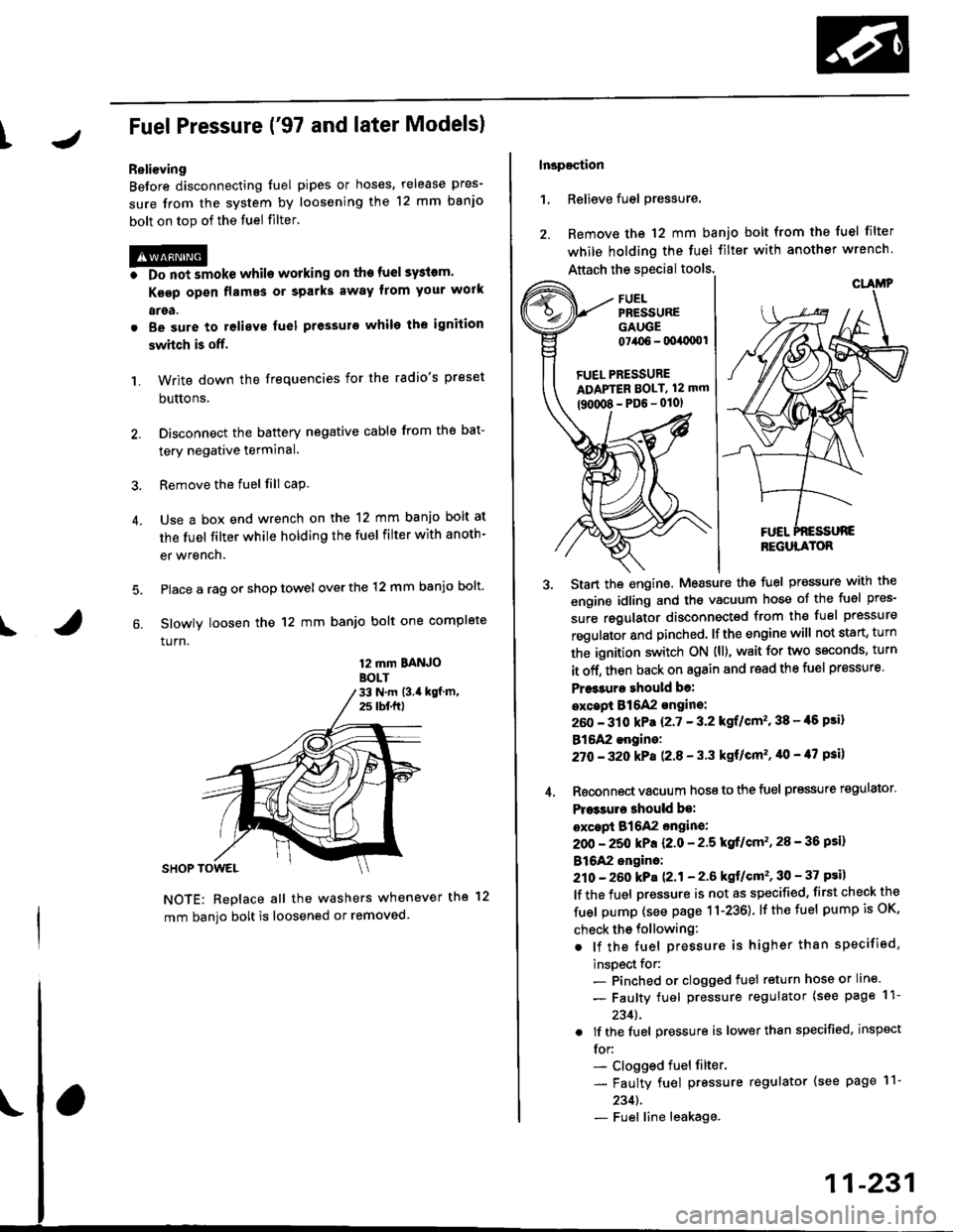
Use a box end wrench on the 12 mm banjo bolt at
the fuel filter while holding the fuel filter with anoth-
er wrench.
Place a rag or shop towel over the 12 mm banio bolt.
Slowly loosen the 12 mm banjo bolt one complete
turn.
4.
I
12 mm BAtt OBOLT33 N.m (3.i1 kgf m,25 tbf.f0
NOTE: Replace all the washers whenever the 12
mm banio bolt is loosened or removed.
Inspaqtion
1. Relieve fuel pressure.
2. Remove the 12 mm banjo bolt from the fuel filter
while holding the fuel Jilter with another wrench
Attach the special tools.
3. Start the enginethe fuel Pressure with the
engine idling and the vacuum hose of the fuel pres-
sure regulator disconnected from the fuel pressure
regulator and pinched lfthe engine will not start, turn
the ignition switch ON {ll), wait for two seconds, turn
it off, then back on again and read the fuel pressure'
Pr$3uro ehould be:
excepi 816A2 sngine:
260 - 310 kPa {2'7 - 3.2 kgf/cm" 38 - {6 Fi}
B16A2 engine:
27O -32O kPa P.8 - 3'3 kgf/cm'�, '10 - 47 psi)
4. Reconnect vacuum hoso to the fuel pressure regulator'
Pre33ure 3hould be:
except B16A2 engin€:
2OO - 250 kPa {2.0 - 2'5 kgf/cm'�, 28 - 36 psi)
B16A2 engino:
210 - 260 kPa 121 - 2.6 ksf/cm'�, 30 - 37 psi)
lf the fuel pressure is not as specified, first check the
fuel pump (see page 11-236) lfthetuel pumpisoK,
check tho following:
. lf the fuel pressure is higher than specified,
inspect for:- Pinched or clogged fuel return hose or line.
- Faulty fuel pressure regulator (see page 11-
2341.
. lf the fuel pressure is lower than specified, inspect
for:- Clogged fuel filter.
- Faulty fuel pressure regulator (see page l1-
2341.- Fuel line leakage.
FUEL PRESSUREADAPTER BOLT, 12 mm
tguxt8-PD6-0101
CLAMP
REGULATOR
11-231
Page 501 of 2189
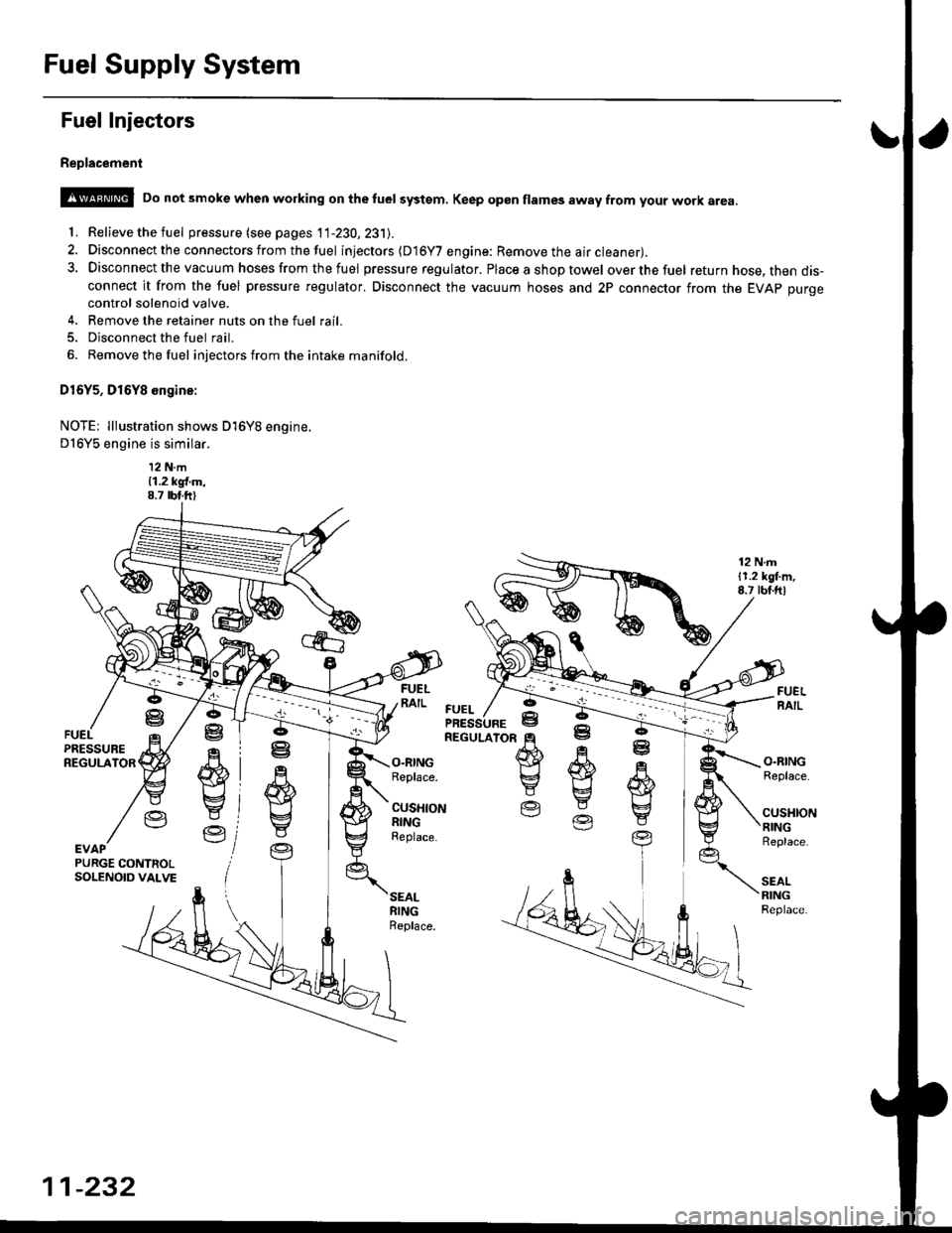
Fuel Supply System
Fuel Injectors
Replacement
@ Do not smoke when working on the tuel systgm, Keep gp6n flames away from your work area
'f. Relieve the fuel pressure (see pages 11-230,231J.
2. Disconnect the connectors from thefuel injectors (D16Y7 engine: Remove the air cleaner).
3. Disconnect the vacuum hoses from thefuel pressure regulator. Placeashoptowel overthefuel return hose, then dis-connect it from the fuel pressure regulator. Disconnect the vacuum hoses and 2P connector from the EVAp purgecontrol solenoid valve.
4. Remove the retainer nuts on the fuel rail.
5. Disconnect the fuel rail.
6. Removethefuel injectors from the intake manifold.
D16Y5, D16Y8 engine:
NOTE: lllustration shows D16Y8 engine.
D16Y5 engine is similar.
12 N.m11.2 kgl.m,8.7 rbt.ft)
12 N.m11.2 lgl.m,8.7 rbt.ftl
.q
wE4
Y
Ve
ffi}Yg
E
O.RINGReplace.
CUSHIONRINGReplace.
O.RINGReplace.
cusl{toNRINGReplace.
SEALRINGReplace.
ffi
E
EV
R
w
t
YEVAPPURGE CONTNOLSOLENOID VALVE
FUEL
11-232
Page 503 of 2189
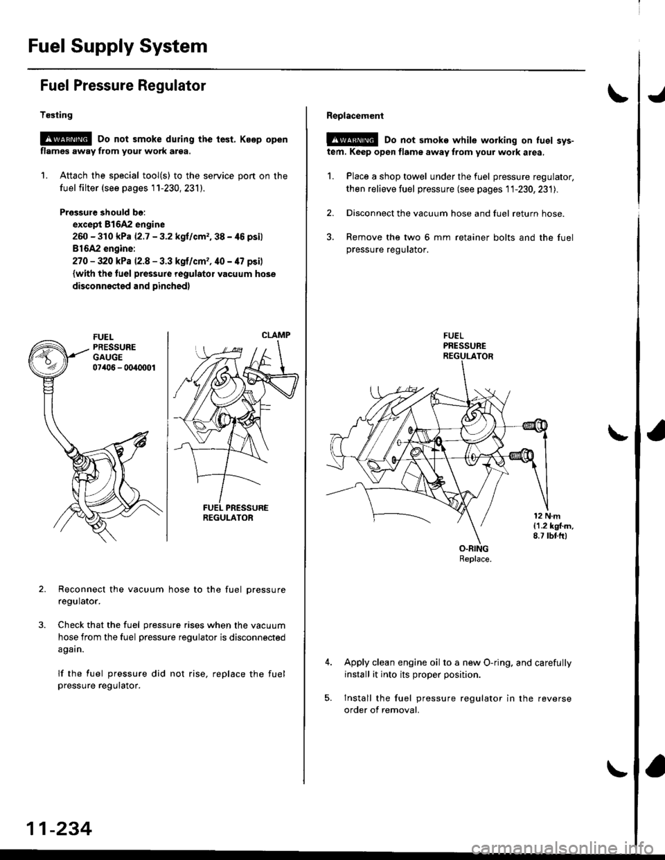
Fuel Supply System
Fuel Pressure Regulator
Te3ting
@ Do not smoke during the tast. Keep open
flamcs away from your work arsa.
1. Attach the special tool(s) to the service port on the
fuel filter (see pages 1 1-230, 231).
Pressure should bo:
except 81642 engine
260 - 310 kPa |'2.7 - 3.2 kgllcrn2,38 - /t6 psil
816A2 engine:
27O - 320 kPa 12.8 - 3.3 kgf/cm,, 40 - 47 psi)
{with the tuel pressure regulator vacuum hose
disconnested and pinched)
Reconnect the vacuum hose to the fuel pressure
regulator.
Check that the fuel pressure rises when the vacuum
hose from the fuel pressure regulator is disconnected
again.
lf the fuel pressure did not rise, replace the fuel
pressure regutalor.
CLAMP
REGULATOR
11-234
Reolacement
@@ Do not smoke while working on luel sys-
tem. Keep open flame away from your work area,
1. Place a shop towel under the fuel pressure regulator,
then relieve fuel pressure (see pages 11-230,231l..
2. Disconnect the vacuum hose and fuel return hose.
3. Remove the two 6 mm retainer bolts and the fuel
pressure regurator.
Apply clean engine oil to a new O-ring. and carefully
install it into its proper position.
Install the fuel pressure regulator in the reverse
order of removal.