tow HONDA CIVIC 2000 6.G Repair Manual
[x] Cancel search | Manufacturer: HONDA, Model Year: 2000, Model line: CIVIC, Model: HONDA CIVIC 2000 6.GPages: 2189, PDF Size: 69.39 MB
Page 1073 of 2189
)
Steering Pump
Construction
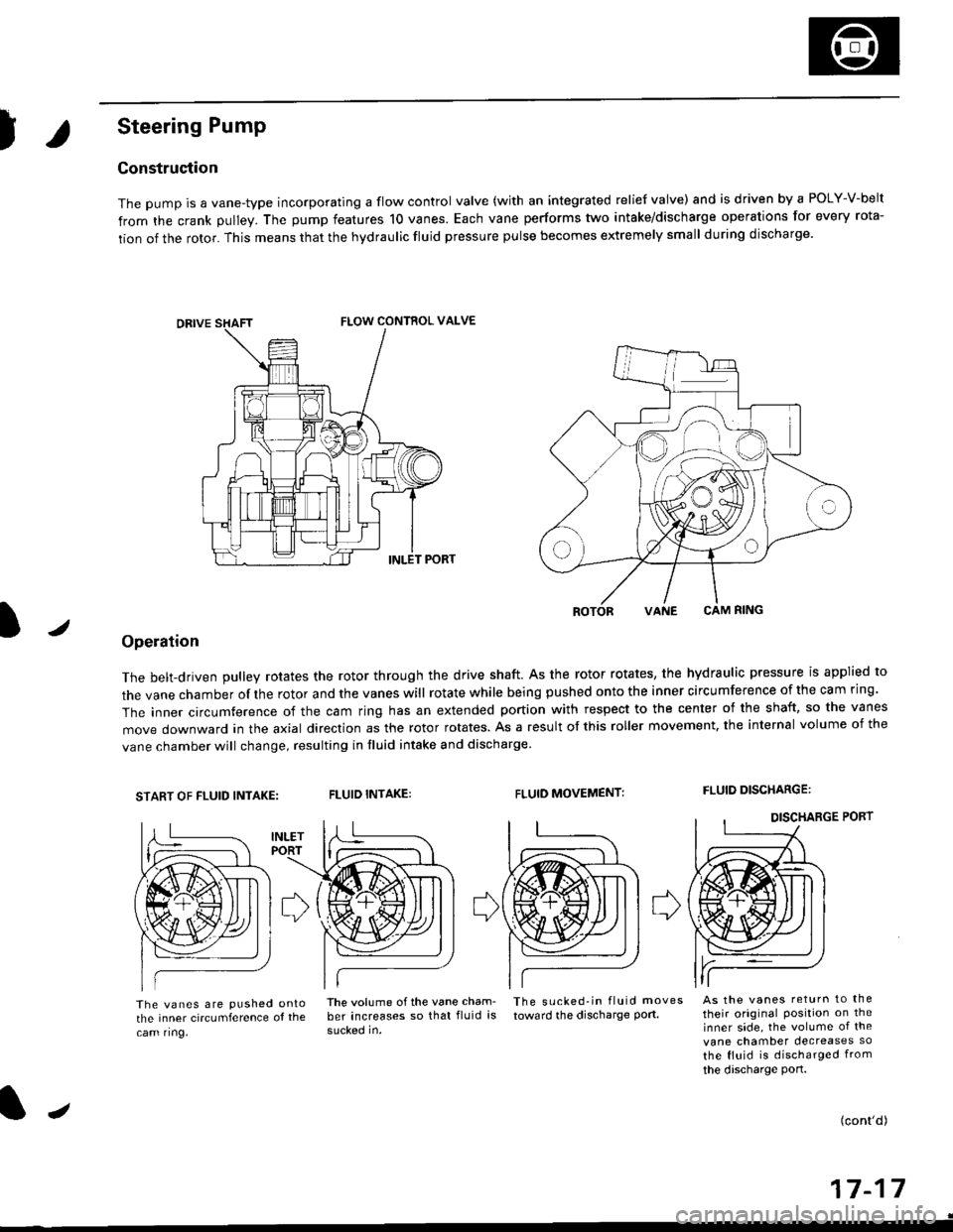
The pump is a vane-type incorporating a flow control valve (with an integrated relief valve) and is driven by a POLY-V-belt
from the crank pulley. The pump features 10 vanes. Each vane performs two intake/discharge operations for every rota-
tion of the rotor. This means that the hydraulic fluid pressure pulse becomes extremely small during discharge.
/
ROTORVANE CAM RING
Operation
The belt-driven pulley rotates the rotor through the drive shaft. As the rotor rotates, the hydraulic pressure is applied to
the vane chamber of rhe rotor and the vanes will rotate while being pushed onto the inner circumference of the cam ring.
The inner circumference of the cam ring has an extended portion with respect to the center of the shaft, so the vanes
move downward in the axial direction as the rotor rotates. As a result of this roller movement. the internal volume of the
vane chamber will change, resulting in fluid intake and discharge
START OF FLUID INTAKE:FLUID INTAKE:FLUID MOVEMENT:FLUID DISCHARGE:
The vanes are pushed ontothe inner circumference ol the
cam ring,
lhe volume ofthe vane cham- The sucked-in fluid moves
ber increases so that fluid is toward the discharge port.
sucked in.
As the vanes return to the
their original Position on theinner side, the volume of the
vane chamber decreases so
the fluid is discharged from
the discharge port.
(cont'd)
a-t 4-I I- | t
FLOW CONTROL VALVE
J
Page 1093 of 2189
Steering Column
I
Removal/lnstallation
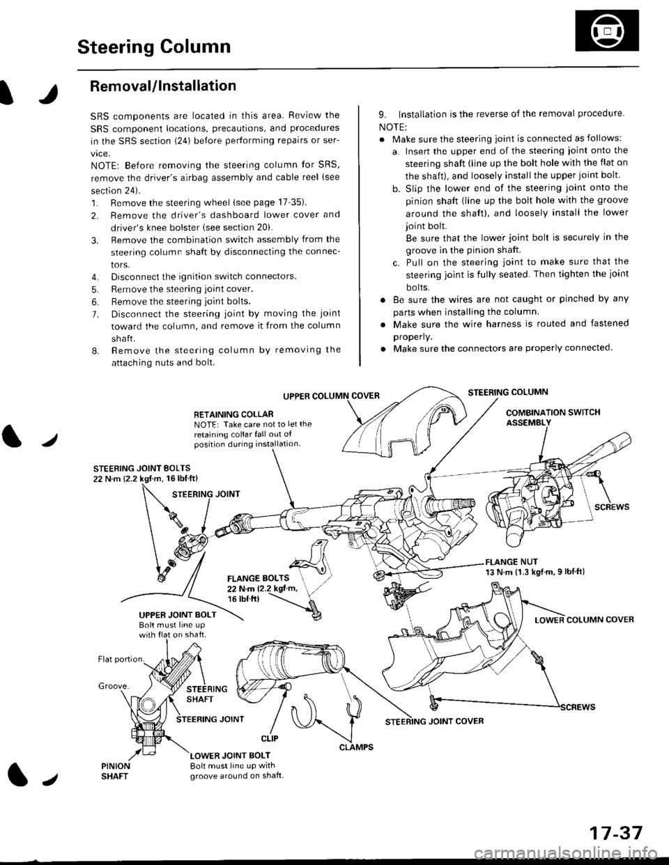
SRS components are located in this area. Review the
SRS component locations, precautions, and proceclures
in the SRS sectron (24) before pertorming repairs or ser-
vice.
NOTE: Before removing the steering column for SRS,
remove the driver's airbag assembly and cable reel lsee
section 24).
1. Remove the steering wheel (see page 17 35).
2. Remove the driver's dashboard lower cover and
driver's knee bolster (see section 20).
3. Remove the combination switch assembly from the
steering column sha{t by disconnecting the connec-
tors.
4. Disconnect the ignition switch connectors.
5. Remove the steering joint cover.
6. Bemove the steering joint bolls.
7. Disconnect the steering ioint by moving the joint
toward the column, and remove it from the column
shaft.
8. Remove the steering column by removing the
attaching nuts and bolt.
UPPER
RETAINING COLLABNOTE: Take care not to let the
retaining collar fall out ofposition during installation.
STEERING JOINT BOLTS22 N.m {2.2 kgf.m, 16lbtft}
9. Installation is the reverse of the removal procedure
NOTE:
. Make sure the steering joint is connected as follows:
a. Insert the upper end of the steering ioint onto the
steering shaft (line up the bolt hole with the flat on
the shait), and loosely install the upper joint bolt.
b. Slip the lower end of the steering joint onto the
pinion shaft (line up the bolt hole with the groove
around the shaft), and loosely install the lower
joint bolt.
Be sure that the lowei joint bolt is securely in the
groove in the pinion shaft.
c. Pull on the steering joint to make sure that the
steering joint js fully seated. Then tighten the ioint
bolts.
. 8e sure the wires are not caught or pinched by any
parts when installing the column
. Make sure the wire harness is routed and fastened
properly.
. Make sure the connectors are properly connected.
STEERING COLUMN
COMBINATION SWITCHASSEMBLY
FLANGE NUT13 N.m {1.3 kgl.m.9 lbf ft)
COLUMN COVER
FLANGE BOLTS22Nm12.2kgl'm,16 tbt.tr)
UPPER JOINT BOLTBolt musl line upon shaft.
Groove.
LOWER JOINT BOLT8oh must line up wrthgroove around on shaft.
CLIP
J
JOINT COVER
17-37
Page 1096 of 2189
Power Steering Pump
RemovaUlnstallation
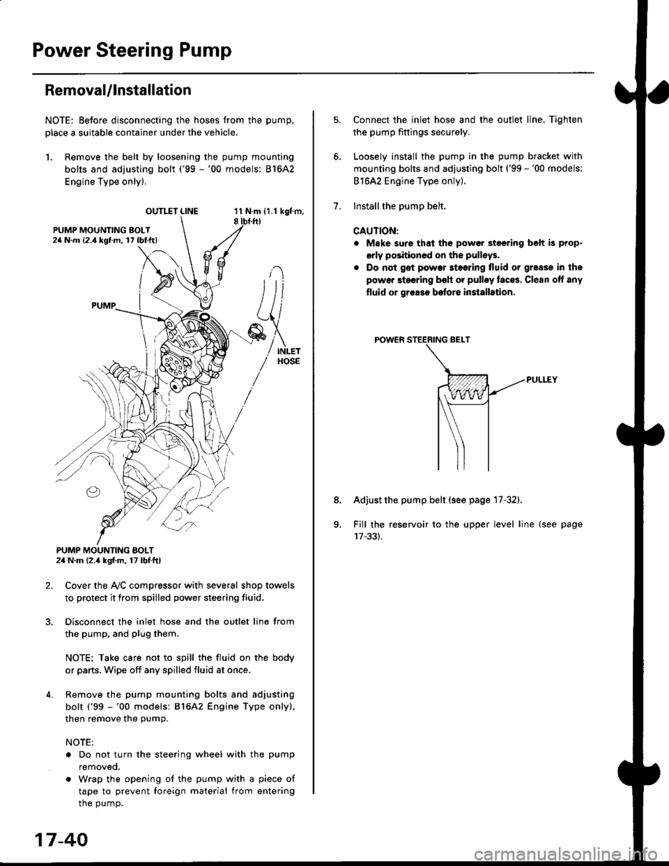
NOTE: Eefore disconnecting the hoses from the pump,
Dlace a suitable container under the vehicle.
1. Remove the belt by loosening the pump mounting
bolts and adjusting bolt ('99 -'00 models: 81642
Engine Type only).
OUTLET LINE11 N.m {1.1 kgf'm,8
L
PUMP MOUNTING BOLT24 N.m (2.4 kgl.m, 17 lbf ft)
2. Cover the Ay'C compressor with several shop towels
to protect it from spilled power steering fluid.
3. Disconnect the inlet hose and the outlet line from
the pump, and plug them.
NOTE: Take care not to spill the fluid on the body
or parts, Wipe off any spilled fluid at once.
4. Remove the pump mounting bolts and adjusting
bolt ('99 -'00 models: 816A2 Engine Type only),
then remove the pump.
NOTE:
. Do not turn the steering wheel with the pump
removeo.
. Wrap the opening of the pump with a piece of
tape to prevent foreign material from entering
the pump.
17-40
1.
8.
Connect the inlet hose and the outlet line. Tiqhten
the pump fittings securely.
Loosely install the pump in the pump bracket with
mounting bolts and adjusting bolt ('99 -'00 models:
81642 Engine Type only).
Installthe pump belt.
CAUTION:
. Make sure that the power steering belt is prop-
orly positioned on the pulleys.
. Do not get power stoering tluid or grease in the
power steering bsh or pulley faces. Clean off any
fluid or grease before installrtion.
Adjust the pump belt (see page 17-32).
Fill the reservoir to the upper level line (see page
Page 1103 of 2189
Steering Gearbox
)
Removal
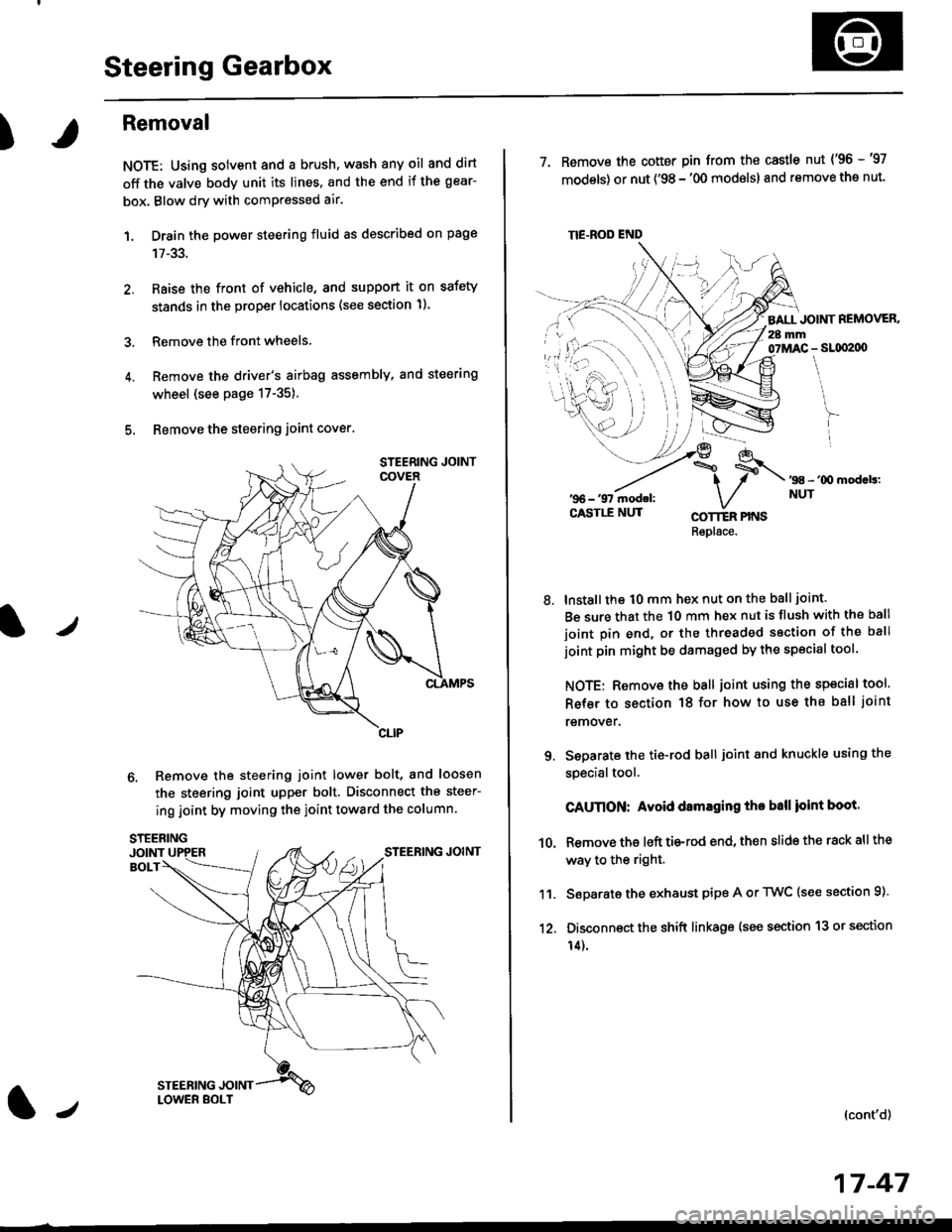
NOTE: Using solvent and a brush, wash any oil and dirt
off the valve body unit its lines. and the end if the gear-
box. Blow dry with comPressed air.
1. Drain the power steering fluid as described on page
2. Raise the front of vehicle, and support it on safety
stands in the proper locations (see section 11.
3, Remove the front wheels.
4. Remove the driver's airbag assembly, and steering
wheel (see page 17-35)
5. Bemove the steering joint cover.
6. Remove the steering joint lower bolt, and loosen
the steering joint upper bolt. Disconnect the steer-
ing joint by moving the ioint toward the column
tJ
17-47
TIE.ROD END
7. Remove the cotter pin from the castle nut {'96 -'97
models) or nut ('98 - '00 modslsl and remove the nut.
BALL JOINT REMOVER.28 mm07MAC - SLqI2|X)
'98 - '00 mod.b:NUT
8.
COTTER PINSRepl6ce.
lnstall the t0 mm hex nut on the ball joint.
Be sure that the 10 mm hex nut is flush with the ball
joint pin end, or the threaded section of the ball
joint pin might be damaged by the special tool.
NOTE: Remove the ball joint using the special tool.
Refer to section 18 for how to use ths ball joint
remover.
Seoarate the tie-rod ball joint and knuckle using the
specialtool.
CAUnON: Avoid damaging tho ball ioint boot.
Remove the left tie-rod end, then slide the rack all the
way to the right.
Separate the exhaust pipe A or TWC (see section 9).
Disconnect the shift linkage (see section 13 or section
14).
(cont'd)
9.
10.
11.
12.
Page 1113 of 2189
I
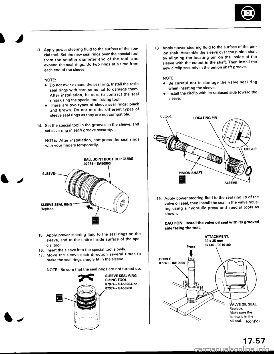
14.
Apply power steering fluid to the surface of the spe-
cial tool. Set the new seal rings over the special tool
from the smaller diameter end of the tool, and
expand the seal rings. Do two rings at a time from
each end of the sleeve.
NOTE;
. Do not over-expand the seal ring. Installthe resin
seal rings with care so as not to damage them'
After installation, be sure to contract the seal
rings using the specialtool (sizing tool).
. There are two types of sleeve seal rings: black
and brown. Do not mix the different types of
sleeve seal rings as they are not compatible
Set the special tool in the grooves in the sleeve, and
set each ring in each groove securely.
NOTE: After installation, compress the seal rings
with your fingers temPorarilY
BALL JOINT BOOI CLIP GUIDE
07S7,1- SA50800
SLEEVE
15. Apply power steering fluid to the seal rings on the
sleeve, and to the entire inside surface of the spe-
cial tool.
16. lnsert the sleeve into the specialtool slowly'
17. Move the sleeve each direction several times to
make the seal rings snugly fit in the sleeve'
NOTE: Be surerings are not turned uP.
SITEVE SEAL RINGSIZING TOOL0797a - SA5020A or07974 - SA50200
that the seal
fr
J
17-57
18. Apply power steering fluid to the surface o{ the pin-
ion shaft. Assemble the sleeve over the pinion shaft
by aligning the locating pin on the inside of the
sleeve with the cutout in the shaft. Then install the
new circlip securely in the pinion shaft groove'
NOTE:
Be careful not to damage the valve seal ring
when inserting the sleeve.
Installthe circlip with its radiused side toward the
sleeve.
Apply power steering fluid to the seal ring lip of the
valve oil seal. then install the seal in the valve hous-
ing using a hydraulic press and special tools as
shown.
CAUTION: Install the valve oil seal with its grooved
side facing the tool.
'19.
ATTACHMENT.32x35mm0774.6 - q)101(x)Pre3s
IDRIVER07749 - 0010000
VALVE OIL SEALReplace.Make sure thespring is in the
oil seal. (cont'd)
Page 1114 of 2189
Steering Gearbox
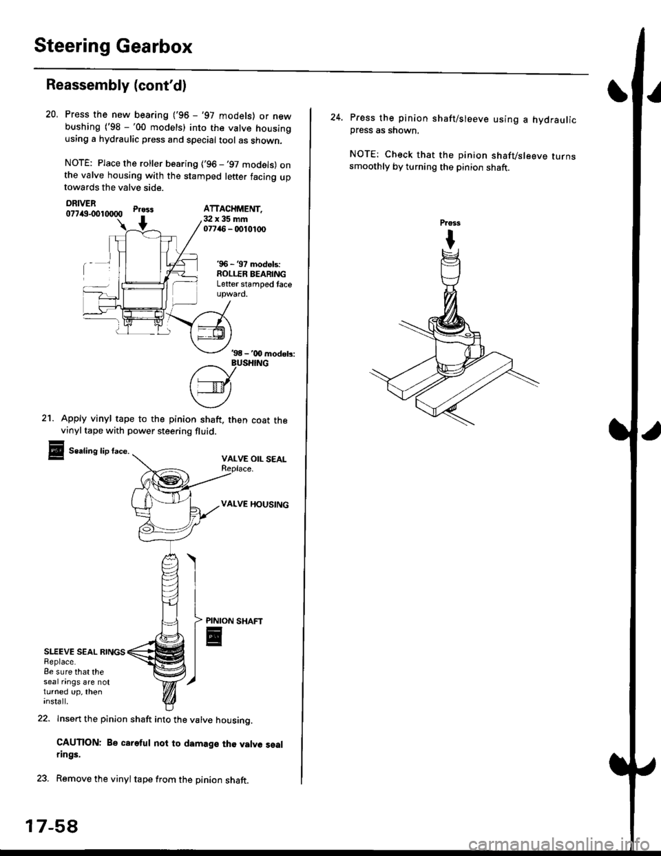
Reassembly (cont'd)
SLEEVE SEAL RINGSReplace.8e sure that theseal nngs are notturned up, theninsta ll.
21. Apply vinyl tape to the pinion shaft. then coat thevinyltape with power steering fluid.
Sealing lip face.VALVE OIL SEAL
VALVE HOUSING
Press the new bearing ('96 - '97 models) or newbushing ('98 -'00 models) into the valve housingusing a hydraulic press and special tool as shown,
NOTE: Place the roller bearing ('96 -'97 models) onthe valve housing with the stamped letter facing uptowards the valve side.
DRIVER077itg-001tXlOO
22. Insert the pinion shaft into the valve housino.
CAUTION: Be careful noi to damage th€ valve sealrings.
23. Remove the vinyltape from the pinion shaft.
20.
Pr033
+3:Ix35mm07746 - 0010,t(x)
'96 - '97 models:ROLLER BEARINGLetter stamped taceupward.
ATTACHMENT,
'98 - '00 modob:
?/_vusHrNG
['---v-lt
\4)
PINION
E
17-5A
24. Press the pinion shaft/sleeve using a hydraulicpress as shown.
NOTE: Check that the pinion shafvsleeve turnssmoothly by turning the pinion shaft.
Page 1115 of 2189
)
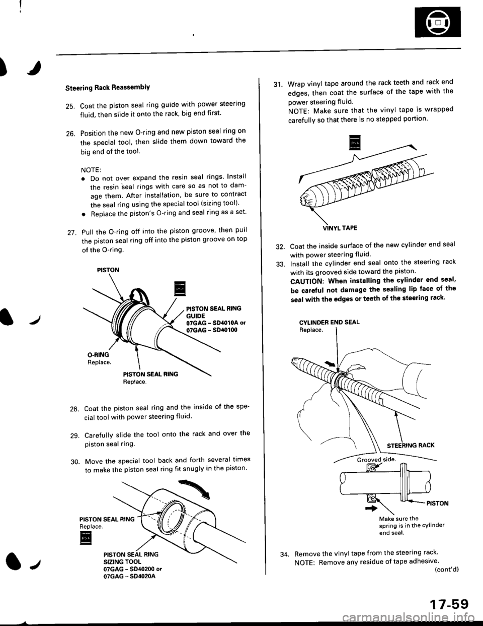
Steering Rack Reassembly
25. Coat the piston seal ring guide with power steering
fluid, then slide it onto the rack, big end first'
26. Position the new O-ring and new piston seal rlng on
the special tool, then slide them down toward the
big end of the tool
NOTE:
. Do not over expand the resin seal rings lnstali
the resin ;eal rings with care so as not to dam-
age them. After installation, be sure to contract
the seal ring using the specialtool (sizing tool)
. Replace the piston's O-ring and seal ring as a set'
27. Pull the O-ring off into the piston groove, then pull
the piston seal ring off into the piston groove on top
ol the O-ring
PISTON SEAL RINGGUIDE07GAG - SD4O10A ol
07GAG - SD,ol(xt
Coat the piston seal ring and the inside of the spe-
cial toolwith power steering fluid.
Carefully slide the tool onto the rack and over the
piston seal ring.
Move the special tool back and forth several times
to make the piston seal ring fit snugly in the piston'
PISTONReplace.
E
PISTON
31. Wrap vinyl tape around the rack teeth and rack end
edges, then coat the surface of the tape with the
power steering fluid
NOTE: Make sure that the vinyl tape is wrapped
carefully so that there is no stepped portion
Coat the inside surface of the new cylinder end seal
with power steering fluid.
Install the cylinder end seal onto the steering rack
with its grooved side toward the piston.
CAUTION: When installing the cylinder end seal,
be caieful not damage the sealing lip face of tho
seal with the edgss or teeth of th€ ste€ring rack'
CYLINDER END SEAL
Make sure thesPring is in the cylinder
end soal
Remove the vinyl tape from the steering rack
NOTE: Remove any residue oftape adhesive(cont'dl
17-59
Page 1117 of 2189
)
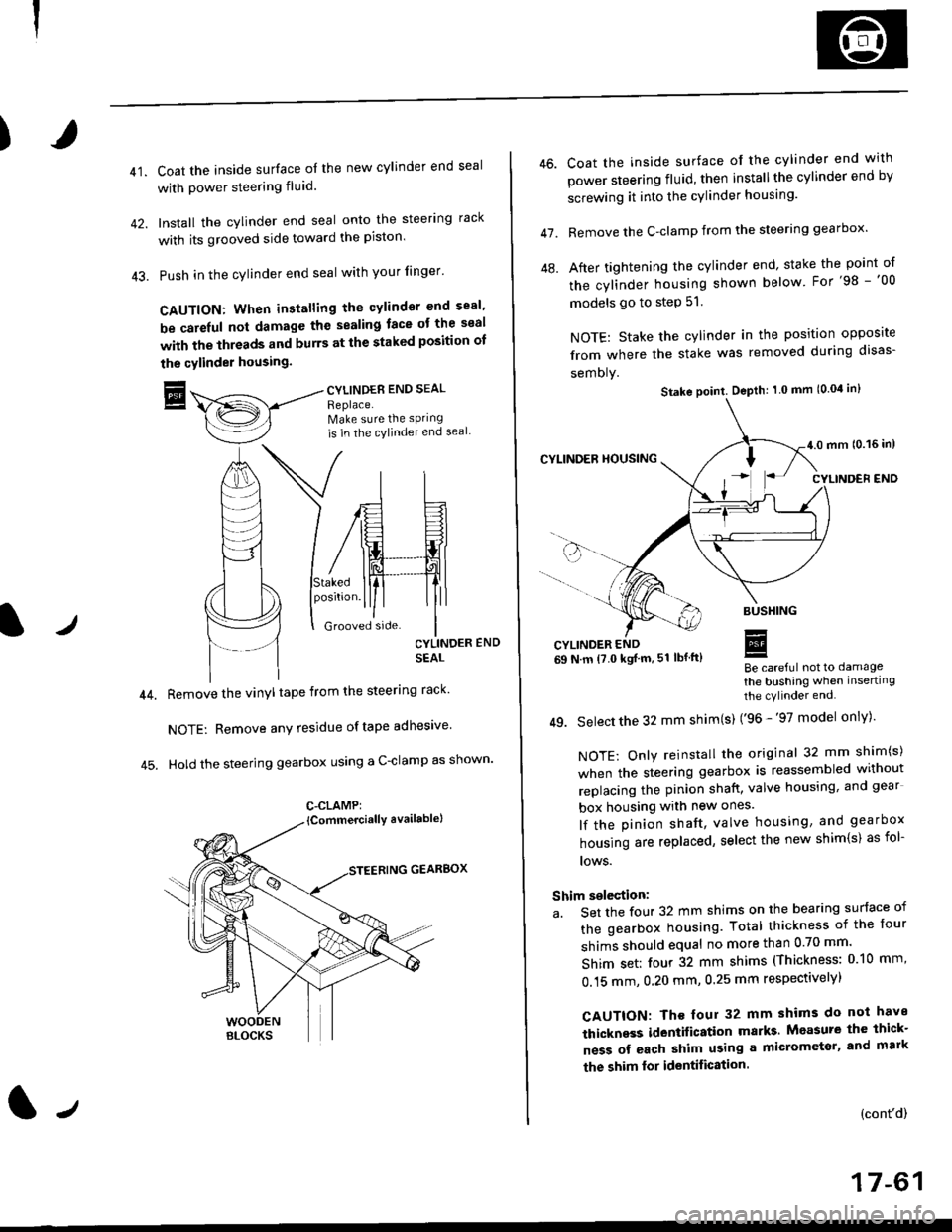
41.Coat the inside surface of the new cylinder end seal
with power steering fluid.
Install the cylinder end seal onto the steering rack
with its grooved side toward the piston'
Push in the cylinder end seal with your finger'
CAUTION: When installing the cylinder end sesl'
be carelul not damage the sealing face ot the seal
with the threads and burrs at the staked position oI
the cylinder housing.
trCYLINDES END SEAL
Replace.Make sure the sPring
is in the cylincler end seal
CYLINDER END
SEAL
Remove the vinyl tape from the steering rack'
NOTE: Remove any residue oftape adhesive
Hold the steering gearbox using a C-clamp as shown'
GEARBOX
C-CLAMP:
l-,
46.
47.
Coat the inside surface of the cylinder end with
power steering fluid, then installthe cylinder end by
screwing it into the cylinder housang.
Remove the C-clamp from the steering gearbox'
After tightening the cylinder end' stake the point of
the cylinder housing shown below For'98 -'00
models go to step 51.
NOTE: Stake the cylinder in the position opposite
from where the stake was removed during disas-
semoly.
Be careful not to damage
the bushing when inserting
the cylinder end.
49. Select the 32 mm shim(s) ('96 -'97 model only)'
NOTE: Only reinstall the original 32 mm shim(s)
when the steering gearbox is reassembled without
replacing the pinion shatt, valve housing, and gear
box housing with new ones.
lf the pinion shaft, valve housing, and gearbox
housing are replaced, select the new shim{s) as fol-
lows.
Shim selection:
a. Set the four 32 mm shims on the bearing surface of
the gearbox housing. Total thickness of the four
shims should equal no more than 0 70 mm'
Shim set: four 32 mm shims (Thickness: 010 mm'
0.15 mm, 0.20 mm, 0.25 mm respectivelyl
CAUTION: Th€ four 32 mm shims do not have
thickness identification marks Measure the thick-
ness of each shim using a micrometsr, and mark
the shim lor identification.
(cont'd)
17-61
Stake point. Depth: 1 0 mm (0.04 in)
Page 1121 of 2189
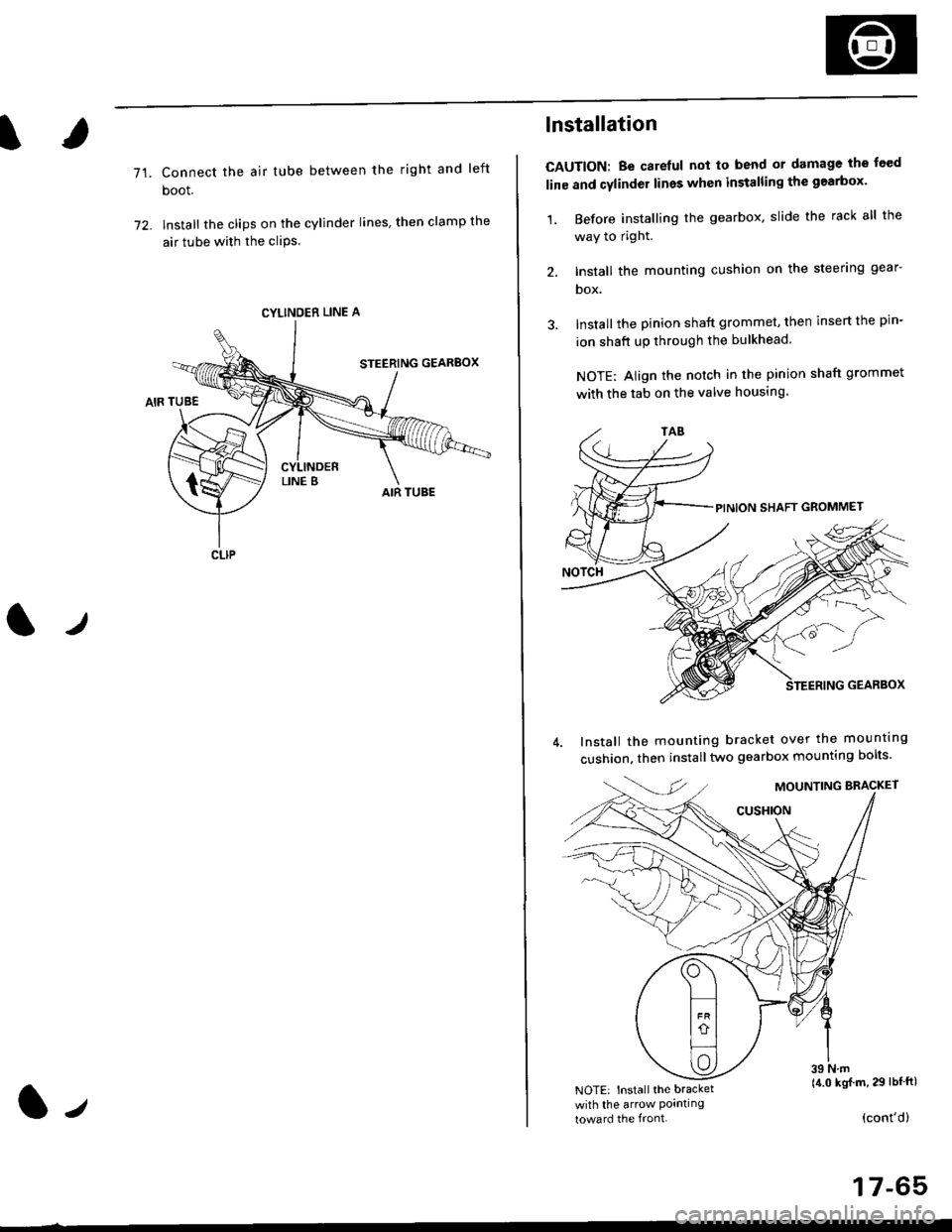
71.Connect the air tube between the right and left
boot.
lnstall the clips on the cylinder lines' then clamp the
air tube with the cliPs.
l./
CYLINDER LINE A
CLIP
l-,
lnstallation
CAUTION: Be carelul not to bend or damage the feed
line and cylinder lines when installing the gearbox'
1, Before installing the gearbox, slide the rack all the
way to right.
2. Install the mounting cushion on the steering gear-
DOX.
Install the pinion shaft grommet, then insert the pin-
ion shaft up through the bulkhead.
NOTE: Align the notch in the pinion shaft grommet
with the tab on the valve housing.
Install the mounting bracket over the mounttng
cushion, then installtwo gearbox mounting bolts'
MOUNTING BRACKET
cusHroN
39 N.m(4.0 kgj m, 29 lbtftlNOTE: Install the bracket
with the arrow Pornllngtoward the front.(cont'd)
17-65
Page 1139 of 2189
I
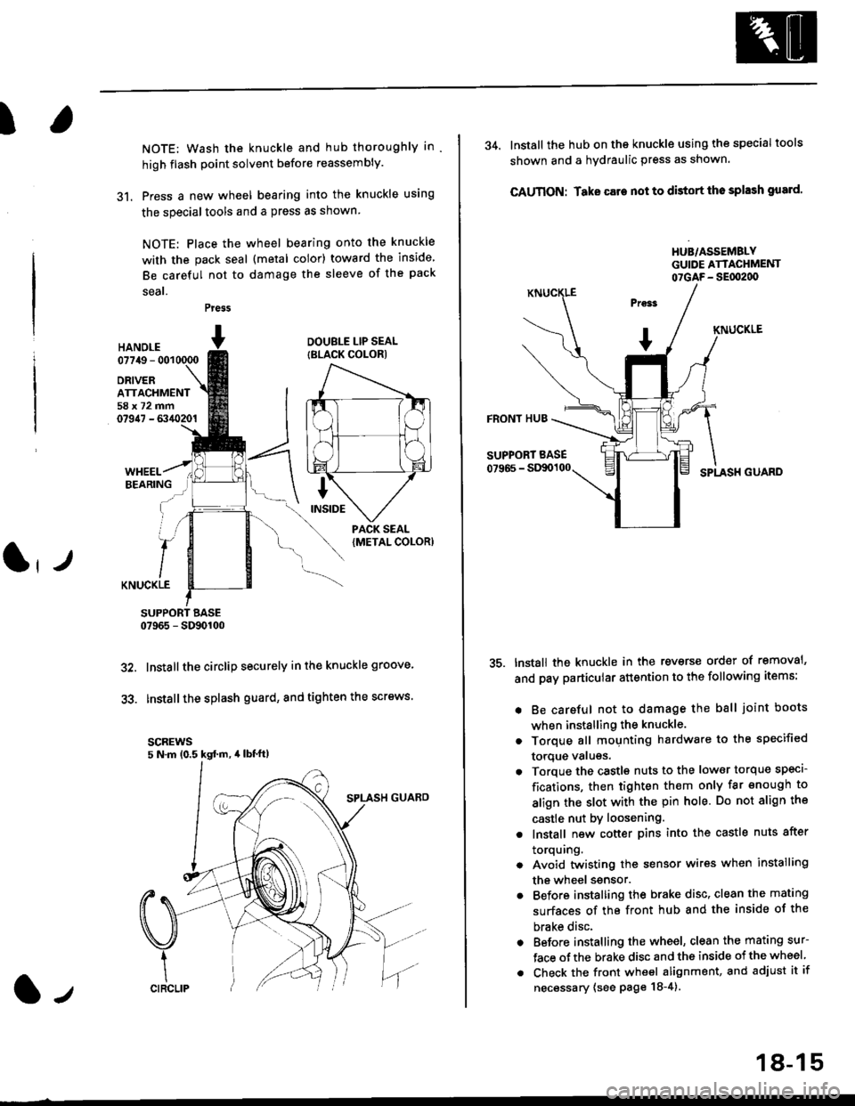
NOTE: Wash the knuckle and hub thoroughly in
high flash point solvent before reassembly.
31. Press a new wheel bearing into the knuckle using
the specialtools and a press as shown
NOTE: Place the wheel bearing onto the knuckle
with the pack seal (metal color) toward the inside
Be careful not to damage the sleeve of the pack
seal.
Press
HANOI.E07749 - 001
DRIVERATTACHMENT58x72mm07947 - 6340201
DOUBLE LIP SEAL
{BLACK COLOR)
KNUCKLE
SUPPORT BASE07965 - SD90100
Installthe circlip securely in the knuckle groove'
Installthe splash guard, and tighten the screws.
scREws5 N.m (0.5 kgd m, 4lbt'ft)
32.
33.
l-,
18-15
34. lnstall the hub on the knuckle using the specialtools
shown and a hydraulic press as shown.
CAUTION: Take care not to distort tho splash gusrd'
HUB/ASSEMBLYGUIDE ATTACHMENT07GAF- SEflt2d)
KNUCKLE
FRONT HUB
SUPPORT BASE
07966 - StXx)100SPLASH GUARD
tnstall the knuckle in the reverse order of removal'
and pay particular attention to the following items:
. Be careful not to damage the ball joint boots
when installing the knuckle.
. Torque all mounting hardware to the specified
torque valugs.
. Torque the castls nuts to the low€r torque specl-
fications, then tighten them only far enough to
align the slot with the pin hole. Do not align the
castle nut by loosening.
. lnstall new cotter pins into the castle nuts after
torquing.
. Avoid twistin0 the sensor wires when installing
the wheel ssnsor.
. Before installing the brake disc, clean the mating
surfaces of the front hub and the inside of the
brake disc.
. Before installing the wheel, clean the mating sur-
face ofthe brake disc and the inside of the wheel
. Check the front wheel alignment, and adjust it if
necessary (see page 18-4).