Lock HONDA CIVIC 2000 6.G Workshop Manual
[x] Cancel search | Manufacturer: HONDA, Model Year: 2000, Model line: CIVIC, Model: HONDA CIVIC 2000 6.GPages: 2189, PDF Size: 69.39 MB
Page 1357 of 2189
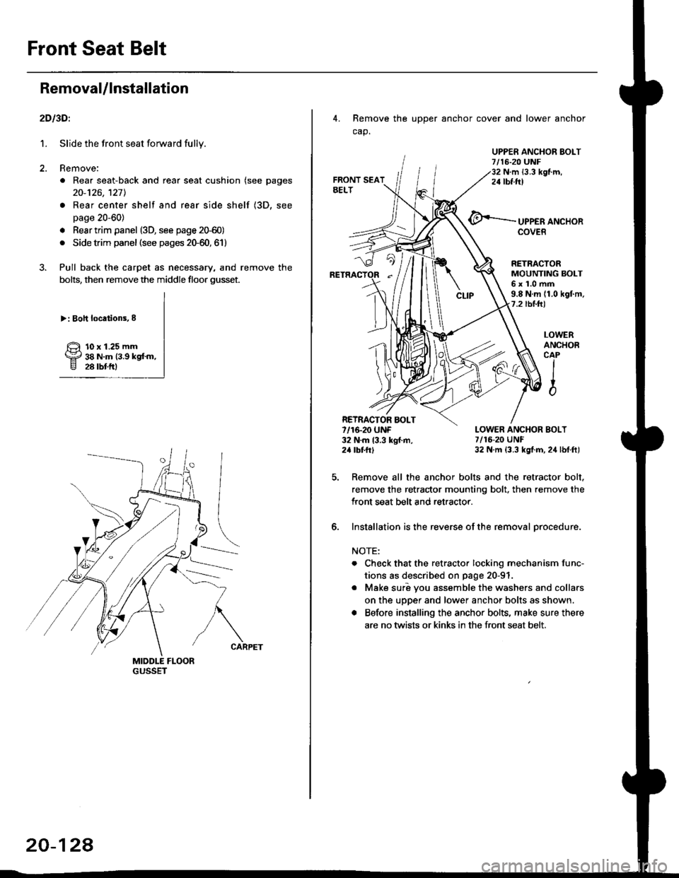
Front Seat Belt
RemovaUlnstallation
2D l3Dl
1. Slide the front seat forward fully.
2. Remove:
. Rear seat-back and rear seat cushion (see pages
20-126,127l.
. Rear center shelf and rear side shelf (3D, see
page 20-60)
. Resr trim panel (3D, see page 2G60)
. Side trim panel (see pages 20-60, 61)
3. Pull back the carpet as necessary, and remove the
bolts, then remove the middle floor gusset.
>: Boh locations,8
10 x 1.25 mm38 N.m (3.9 kgf'm,28 rbtftl
20-124
4. Remove the upper anchor cover and lower anchor
cap.
UPPER ANCHOR EOLT7/16-20 UNF32 N.m {3.3 kgf.m,24 tbf.ftt
UPPER ANCHORCOVER
LOWERANCHOBCAPIIio
RETRACTORMOUNTING BOLT6x1.0mm9.8 N.m (1.0 kgf.m.7.2 tbl.hl
LOWER ANCHOR BOLT7/16-20 UNF32 N.m (3.3 kgt.m, 24 lbf.ft)
Remove all the anchor bolts and the retractor bolt.
remove the retractor mounting bolt, then remove the
Iront seat belt and retractor.
Installation is the reverse of the removal orocedure.
NOTE:
. Check that the retractor locking mechanism func-
tions as described on page 20-91
o Make suri vou assemble the washers and collars
on the upper and lower anchor bolts as shown.
. Before installing the anchor bolts, make sure there
are no twists or kinks in the front seat belt.
RETRACTOR AOLT7/16-20 UNF32 N.m 13.3 kgf.m,24 tbttrl
6.
Page 1360 of 2189
Body ('98 model)
Opener and Latch
Hood Latch Cover Replacement ""'.' 20-132
Hatch Handle Replacement ..'.'....'...' 20-132
Hatch Latch/Lock CYlinder
Replacement "...'.."..'.'... 20-133
Outline of '98 Model Changes
. The hood latch cover was added
. The hatch handle was added (3D)
Page 1362 of 2189
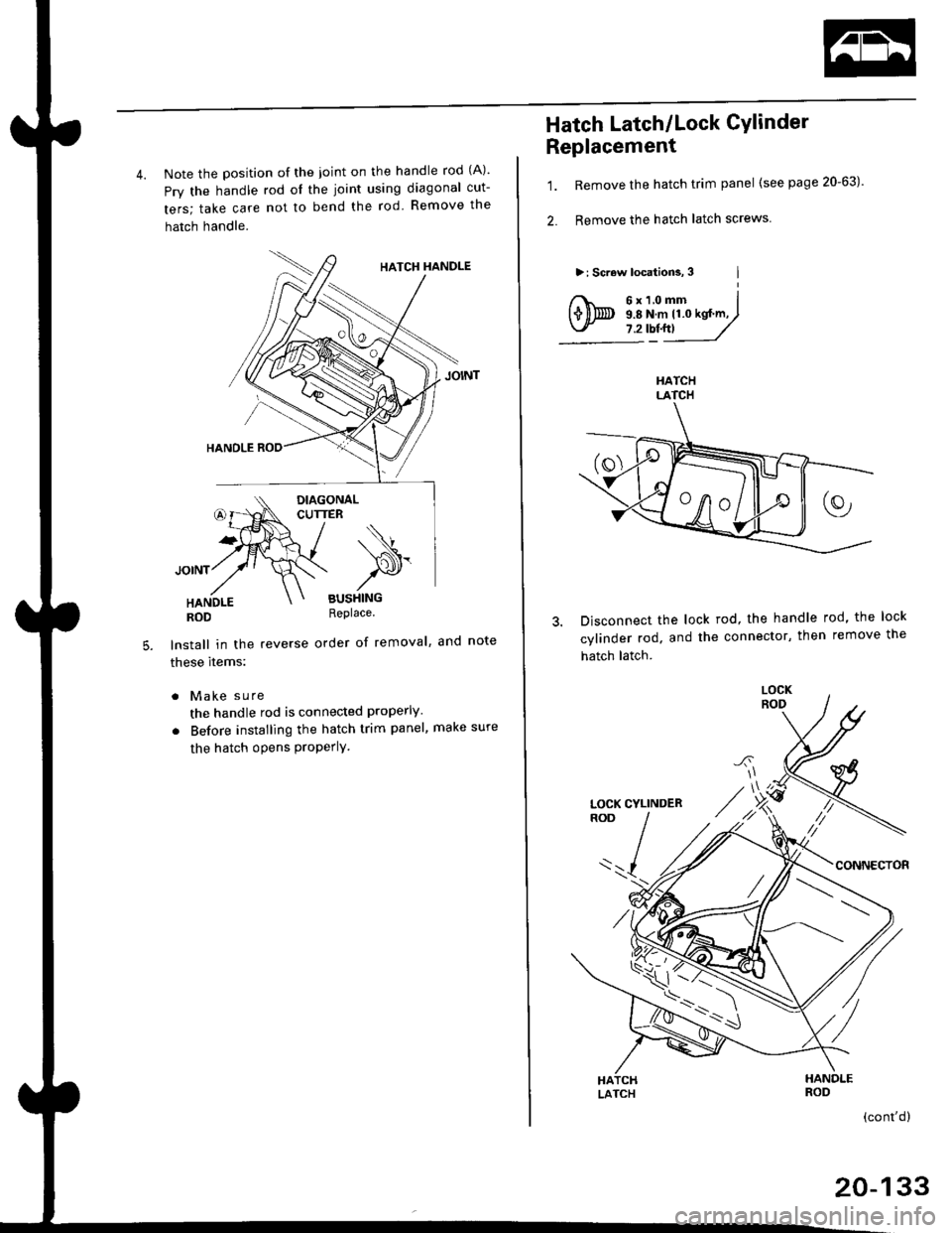
4. Note the position of the ioint on the handle rod (A)'
Prv the handle rod ol the joint using diagonal cut-
ters; take care not to bend the rod Remove the
hatch handle.
BUSHINGReplace.
lnstall in the reverse order of removal, and note
these items:
Make sure
the handle rod is connected properly
Before installing the hatch trim panel, make sure
the hatch opens ProPerlY.
@
Hatch Latch/Lock CYlinder
Replacement
1.
2.
Remove the hatch trim panel (see page 20-63)'
Remove the hatch latch screws
>: Screw locations,3
6x1,0mm9.8 N.m 11.0 kgf'm,
7.2 tbt f0
HATCHLATCH
Disconnect the lock rod, the handle rod, the lock
cylinder rod. and the connector, then remove the
hatch latch.
LOCK CYLINDERROD
''---tCONNECTOR
HANDLEROD
(cont'd)
20-133
Page 1363 of 2189
Opener and Latch
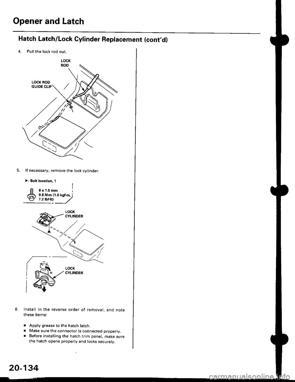
Hatch Latch/Lock Cylinder Replacement (cont'd)
4. Pullthe lock rod out.
lf necessary, remove the lock cylinder.
>: Bolt locelion. 1
6xr.omm I9.8 N.m (1.0 kq .m, I9.8 N.m (1.0 kq .m, I,:!!_J
6. Install in the reverse order of removal, and note
these atems:
. Apply grease to the hatch latch.. Make sure the connector is connected properly.. Before installing the hatch trim panel, make surethe hatch opens properly and locks securely.
ry*)*,,
\""<,/
.z ,/\
20-134
Page 1371 of 2189
Seat Belts
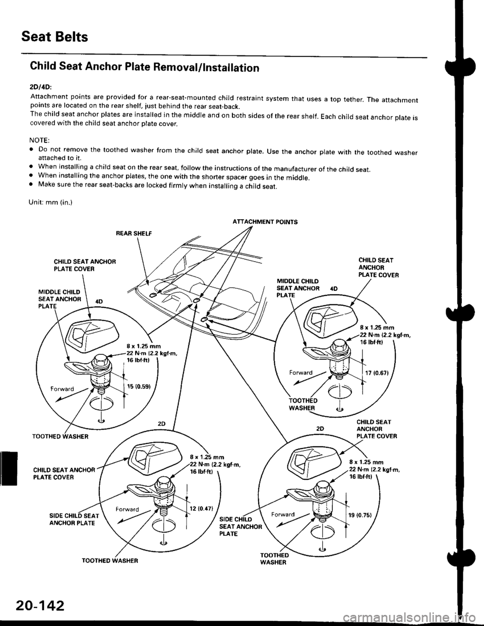
Child Seat Anchor Plate Removal/lnstallation
2DllDl
Attachment points are provided for a rear-seal-mounted child restraint system that usespoints are located on the rear shelf, tust behind the rear seat-back.The child seat anchor plates are installed in the middle and on both sides of the rear shelf.covered with the child seat anchor olate cover.
a top tether. The attachment
Each child seat anchor plate is
NOTE:
' Do not remove the toothed washer from the child seat anchor plate, Use the anchor plate with the toothed washerattached to it.
. When installing a child seat on the rear seat, follow the instructions of the manufacturer of the child seat.. When installing the anchor plates, the one with the shoner spacer goes in the middle.. Make sure the rear seat-backs are locked firmly when installing a child seat.
Unit: mm (in.)
REAR SHELF
CIIILD SEAT ANCHORPLATE COVER
MIDOLE CHILDSEAT ANCHOR
CHILO SEATANCHORPLATE COVER
CHILD SEATANCHORPLATE COVER
8 x 1.25 mm22 N.m 12.2 kgl m,
PLA
8 x 1.25 mm22 N.m 12.2 kgl.m,
I x 1.25 mm22 N.m 12.2 kgl.m,16 tbt.ftt
17 {0.67)
16 tbf.ft)
15 {0.s9)
WASHER
rl)
.t
TOOTHEO
ll ff*,".rd,',i"'"o*
SIDESEAT
I x 1,25 mmN.m {2.2 kgf.m.16 tbtftl
SIDE
16 tbf ftl
ANCHOR PLATESEAT ANCHORPLATE
ATTACHMENT POINTS
torward .
20-142
TOOTHED
12lO.47l19 (0.75)
Page 1372 of 2189
3D:
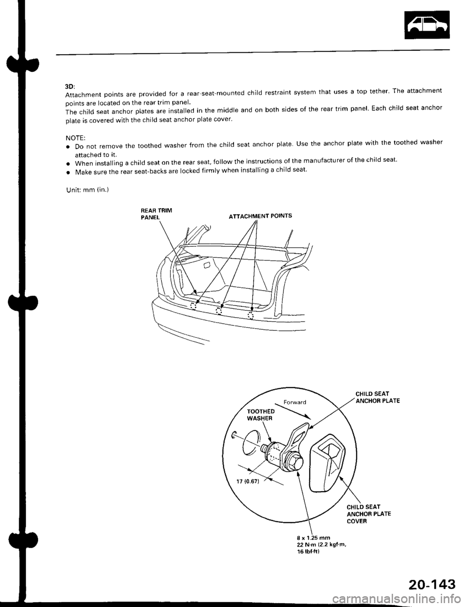
Attachment points are provided for a rear-seat mounted child restraint system that uses a top tether' The attachment
points are located on the rear trim panel.
The child seat anchor plates are rnstalled in the middle and on both sides of the rear trim panel Each child seat anchor
plale is covered with the child seat anchor plate cover'
NOTE:
. Do not remove the toothed washer from the child seat anchor plate. use the anchor plate with the toothed washer
attached to it.
. when installing a child seat on the rear seat, follow the instructions ol the manufacturer of the child seat'
. Make sure the rear seat-backs are locked firmly when installing a child seat'
gn;1 6rn (in.)
ATTACHMENT POINTS
CHILO SEATANCHOR PLATE
CHILD SEATANCHOB PLATECOVER
8 x 1.25 mm22 N..n (2.2 kgl'm.16 tbfft)
;x?',rff{-*.
20-143
Page 1416 of 2189
Heater Control Panel
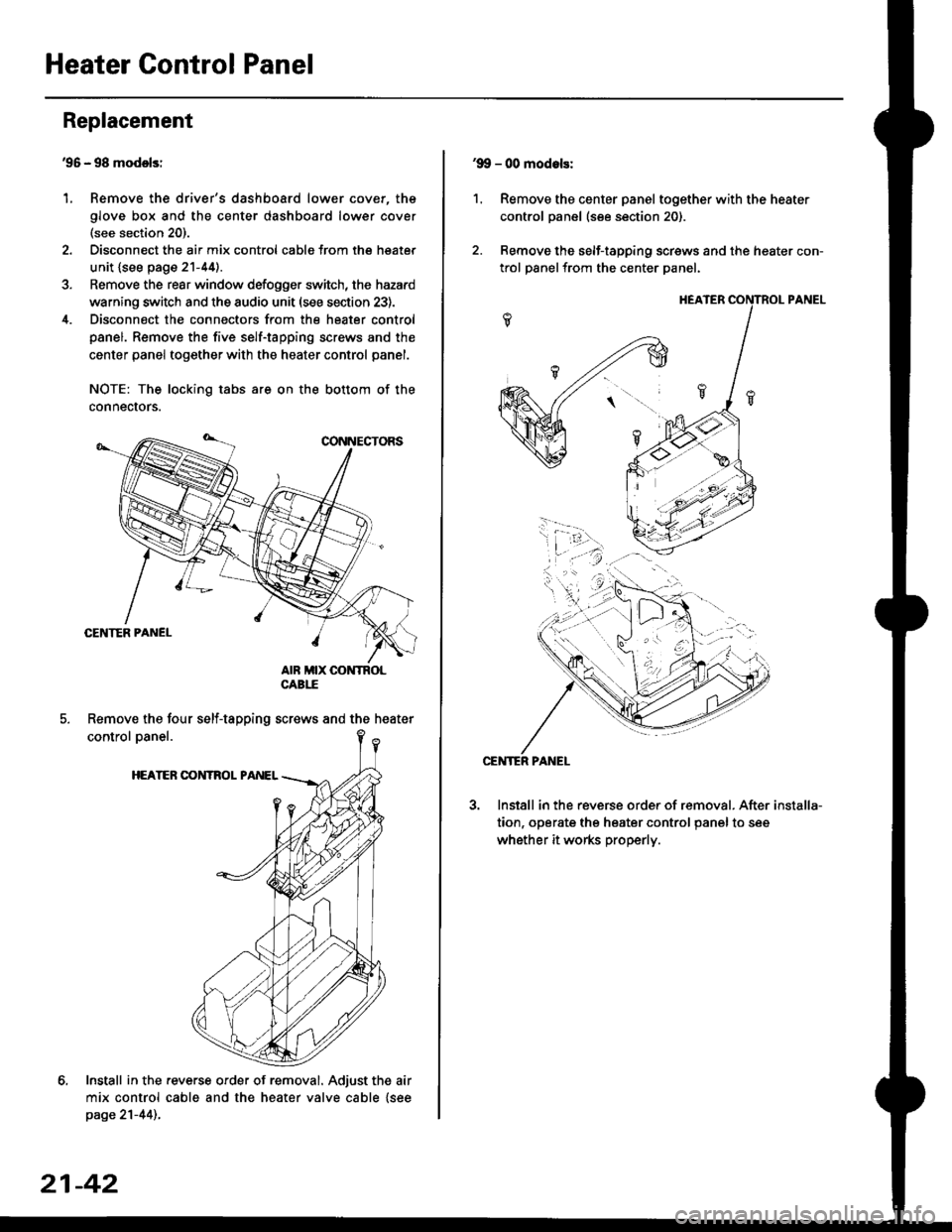
'95 - 98 modolsi
Remove the driver's dashboard lower cover, the
glove box and the center dashboard lower cover(see section 20).
Disconnect the air mix control cabls from the heater
unit {see page 21-44).
Remove the rear window defogger switch, the hazard
warning switch and the audio unit (see section 23).
Disconnect the connectors from the heater control
panel. Remove the five self-tapping screws and the
center panel together with the heater control panel.
NOTE: The locking tabs are on the bottom of the
connecrors.
Install in the .everse order of removal. Adjust the air
mix control cable and the heater valve cable {seepage 21-44)..
Replacement
1.
Remove the four self-tapping screws and the heater
21-42
1.
'9!, - 00 modols:
Remove the center panel together with the heater
control panel (see section 20).
Remove the self-tapping screws and the heater con-
trol panelfrom the center Danel.
Install in the reverse order of removal. After
tion, operate the heater control panel to see
whether it works properly.
installa-
Page 1417 of 2189
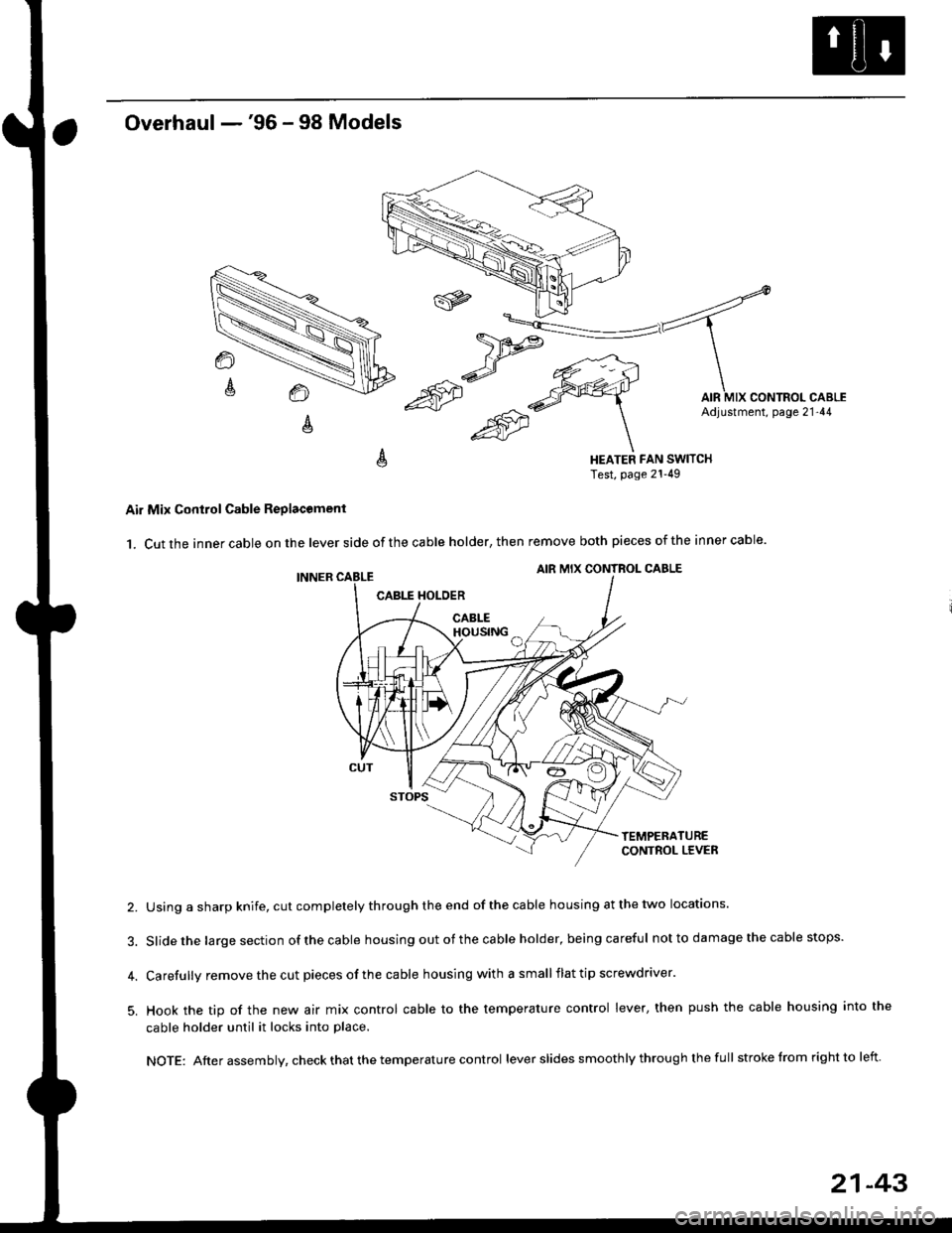
Overhaul -'96 - 98 Models
HEATER FAN SWITCHTest, page 21-49
Air Mix Control Cable Replacomenl
1. Cut the inner cable on the lever side of the cable holder, then remove both pieces of the inner cable.
2. Using a sharp knife, cut completely through the end of the cable housing at the two locations.
3. Slidethe largesection ofthecable housing outofthe cable holder, being careful not to da mage the cable stops.
4. Carefully remove the cut pieces of the cable housing with a small flat tip screwdriver.
5. Hook the tip of the new air mix control cable to the temperature control lever, then push the cable housing into the
cable holder until it locks into place.
NOTE: After assembly, check that the temperature control lever slides smoothly through the full stroke lrom right to left.
21-43
Page 1424 of 2189
Mode Control SwitchPower Transistor
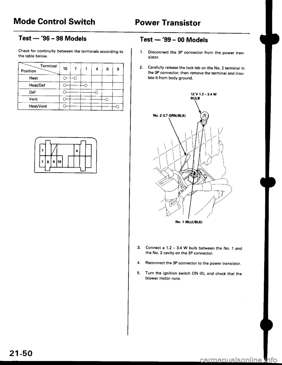
Test -'96 - 98 Models
Check for continuity between the terminals accordinq tothe table below.
Terminal
Position't071
Heato-o
HeaVDefo---o
Defo--o
VentG-o
HeaVVento--o
1
;l t
4
789
21-50
Test -'99 - 00 Models
1. Disconnsct the 3P connector from the oower tran-stsror.
2, Carefully release the lock tab on the No. 2 terminal inthe 3P connector, then remove the terminal and insu-late it from body glound.
Connect a 1.2 - 3.4 W bulb between the No. 1 andthe No. 2 cavity on the 3P connector.
Reconnect the 3P connector to the power translstor.
Turn the ignition switch ON fll), and check that theblower motor runs.
12V 1.2-3,1W
No. 1 laLU/aLK)
Page 1427 of 2189
lllustrated Index
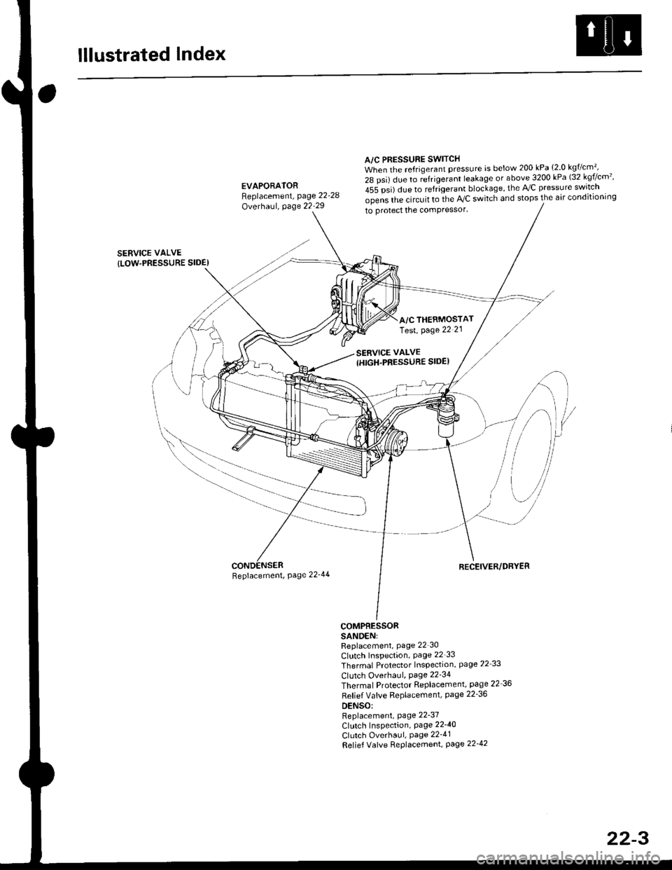
A/C PRESSURE SWITCHWhen the refrigerant pressure is below 200 kPa {2 0 kg7cm'�,
28 psi) due to ;frigerant leakage or above 3200 kPa (32 kgf/cm'�'
455 psi) due to refrigerant blockage, the lVC pressure swrtch
SERVICE VALVE
{LOW.PRESSURE SIDE)
EVAPORATORReplacement, page 22-28
Overhaul, page 22 29
Beplacement, Page 22'44
opens lhe circuit to ihe AVC switch and stops the air condilioning
to protect the comPressor'
RECEIVER/DRYER
COMPRESSORSANDENIReplacement, Page 22 30
CIutch Inspection, Page 22 33
Thermal Protector Inspection, page 22 33
Clutch Overhaul, Page 22'34
Thermal Protector Replacement, page 22 36
Refief Vafve Replacemenl, page 22'36
DENSO:Replacement, Page 22-37
Clutch Inspection, Page 22-40
Clutch Overhaul, Page 22_41
Relief Valve Replacement, page 22-42
A/C THERMOSTATTest, page 22 21
22-3