Lock HONDA CIVIC 2000 6.G Workshop Manual
[x] Cancel search | Manufacturer: HONDA, Model Year: 2000, Model line: CIVIC, Model: HONDA CIVIC 2000 6.GPages: 2189, PDF Size: 69.39 MB
Page 1186 of 2189
Rear Brake Caliper
Reassembly (cont'dl
L
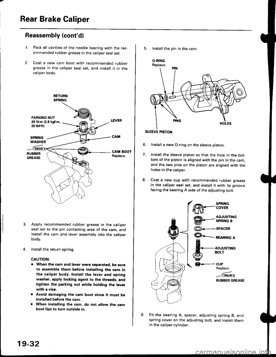
PARKING NUT28 N.m (2.8 kgt m,20 rbr.trt
Pack all cavities of the needle bearing with the rec,
ommended rubber grease in the caliper seal set,
Coat a new cam boot with recommended rubbergrease in the caliper seal set, and install it in thecaliper body.
SPRII{GWASHEN
z..-_e!!!9!.{RUBBERGREASE
Apply recommended rubber grease in the caliperseal set to the pin contacting area of the cam, andinstall the cam and lever assembly into the caliperbodv.
lnstall the return spring.
CAUTION:
. When the cam and lever wgre separatod. b€ surgto assemble them bofore installing the cam inthe caliper body, Install the lev€r and spring
washer. apply locking agent to the threads, andtighten the parking nut while holding the l.vorwhh a vise,
. Avoid damaging the cam boot since it must bsinstalled before thg cam.. When installing the cam, do nol allow the camboot lips lo turn outside in.
19-32
5. Installthe pin in the cam.
O.RINGReplace.
SLEEVE PISTON
Install a new O-ring on the sleeve pisron.
Install the sleeve piston so that the hole in the bot-tom of the piston is aligned with the pin in the cam,and the two pins on the piston are aligned with theholes in the calioer.
Coat a new cup with recommended rubber grease
in the caliper seal set, and install it with its groove
facing the bearing A side of the adjusting bolt.
7.
€8.--:BTif
@'-.-3nfi""'i"
@--seacrn
$ eeenrne a
fi,*,*^"
GF-
Fit the bearing A, spacer. adjusting spring B, andspring cover on the adjusting bolt, and install themin the caliDer cvlinder.
CUPReplace.
=^.#-g!!!!!Jl
RUBBER GREASE
o
Page 1187 of 2189
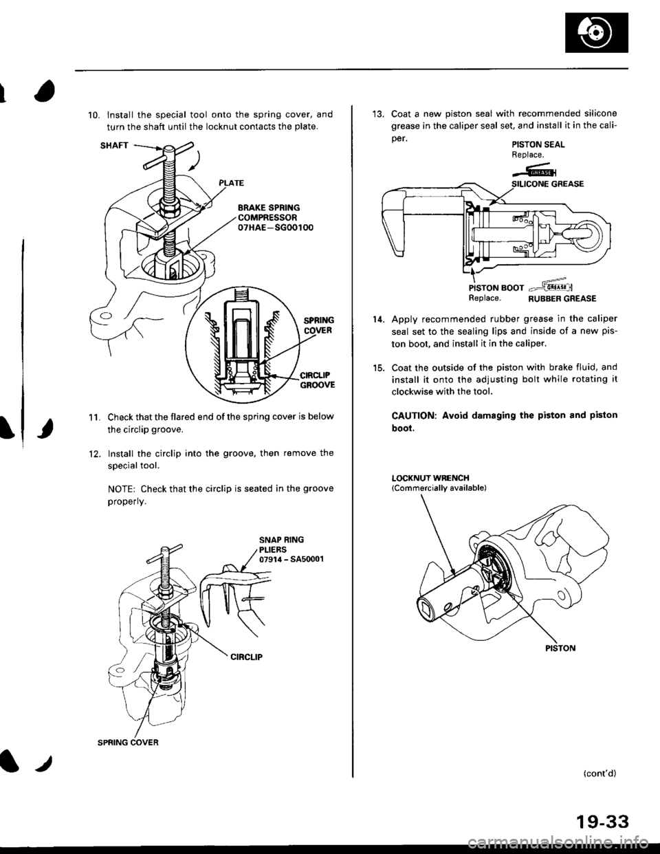
10. lnstall the special tool onto the spring cover, and
turn the shaft until the locknut contacts the plate.
Check that the flared end of the spring cover is below
the circlip groove.
Install the circlip into the groove. then remove the
special tool.
NOTE: Check that the circlip is seated in the groove
properly.
11.
12.
CIRCLIP
t.t
SPRING COVER
13. Coat a new piston seal with recommended silicone
grease in the caliper seal set, and install it in the cali-
per.
PISTON BOOTReplace. RUBBER GREASE
Apply recommended rubber grease in the caliper
seal set to the sealing lips and inside of a new pis-
ton boot, and install it in the caliper.
Coat the outside of the piston with brake fluid, and
install it onto the adjusting bolt while rotating it
clockwise with the tool.
CAUTION: Avoid damaging the piston and piston
boot.
PISTON SEALReplace.
-6l
14.
PISTON
(cont'd)
19-33
Page 1188 of 2189
Rear Brake Caliper
Reassembly (cont'dl
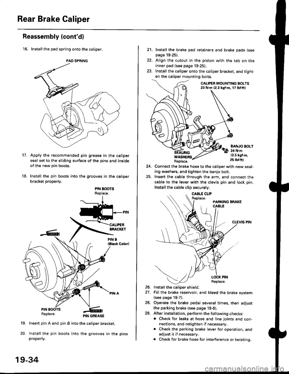
'16. Installthe pad spring onto the caliper.
Apply the recommended pin groase in the caliper
seal set to the sliding surface of the pins and inside
of the new pin boots.
Install the pin boots into the grooves in the caliper
bracket properly.
PIN BOOTSReplsce.
(Bl.ck Colorl
PINRepl6ce.
19. Insert pin A and pin B into the caliper bracket.
20. Install the pin boots into the grooves in thepropefly.
PAD SPRING
11.
PIN GREASE
19-34
pr ns
22.
21. Install the brake pad retainers and brake pads (see
page 19-25).
Align the cutout in the piston with the tab on the
inner pad (see page 19-25).
Install the caliper onto the caliper bracket. and tight-
en the caliper mounting bolts.
CALIPER MOUNTING BOLTS23 N.m {2.3 kg{.m. 17 lbf.ft)
WASHERSReplace.
BANJO BOLT34 N.m13.5 kg{.m.25 rbtft)
24.Connect the brake hose to the caliper with new seal,
ing washers, and tighten the banjo bolt,
Insert ths cable through the arm, and connect the
cabls to the lever with the clevis pin and lock pin.
Install the cable clip securely.
CLEVIS PIN
-t
//t
LOCK PINRoplace.
26. Install the caliDer shield.
27. Fill the brake reservoir, and bleed the brake svstem(see page 19-71.
28. Operate the brake pedal several times, then adjust
the parking brake (see page 19-6).
29. After installation, perform the following checks:. Check for leaks at hose and line joints and con-nections, and retighten if necessary.. Check the parking brake lever for operation, and
adjust it if necessary.
. Check for brake hose for interference or twistinq.
Page 1189 of 2189
Rear Drum Brake
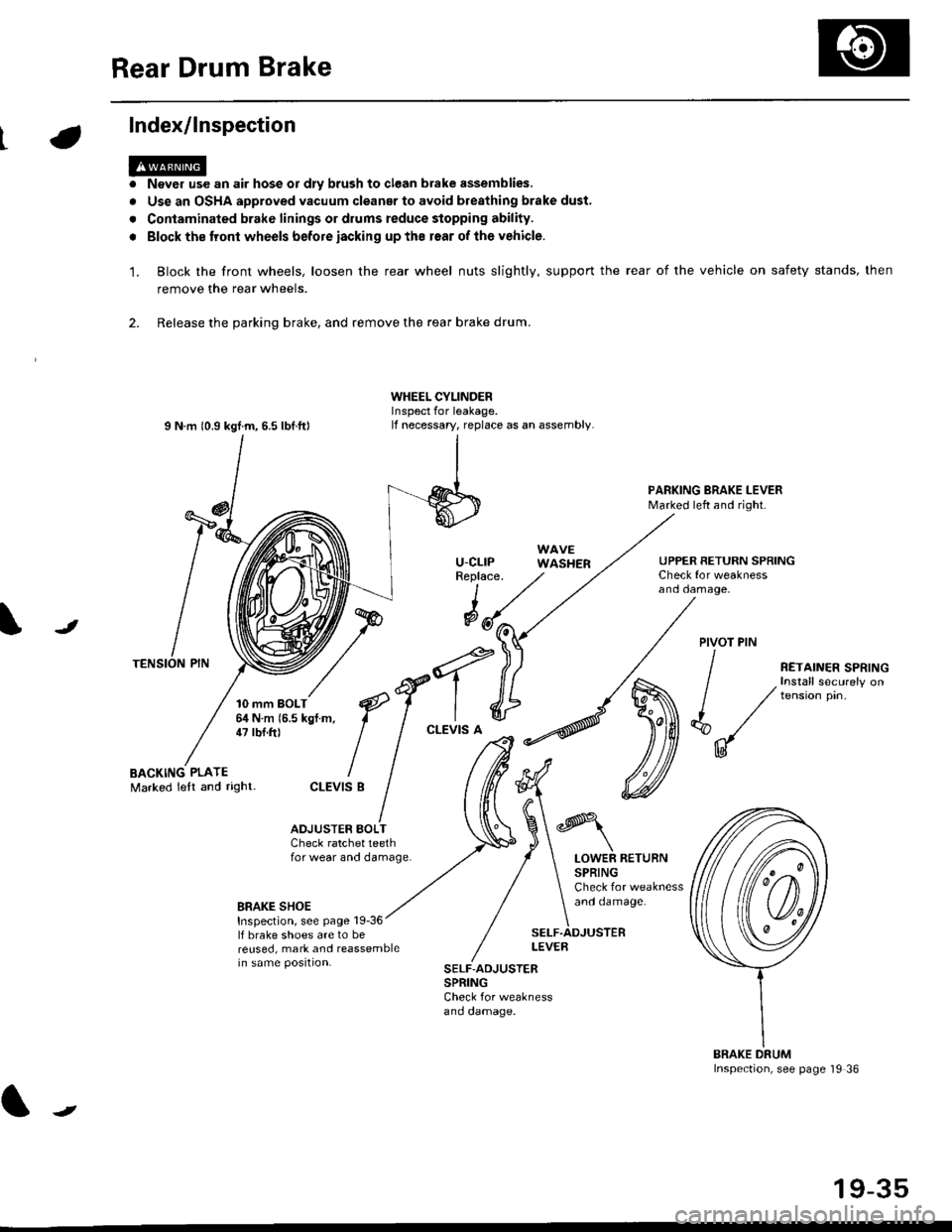
Index/lnspection
'1.
a
a
Never use an air hose or dly brush to clean brake assemblies,
Use an OSHA approved vacuum cleanar to avoid breathing brake dust,
Contaminated brake linings or drums reduce stopping ability.
Block the tront wheels before iacking up ths r€ar of lhe vehicle.
Block the front wheels, loosen the rear wheel nuts slightly, support the rear of the vehicle on safety stands, then
remove the rear wheels.
2. Release the parking brake, and remove the rear brake drum.
I N m 10.9 kgtm, 6.5 lbf.ftl
TENSION PIN
10 mm BOLT6,1N m 15.5 kgf m,47 tbf.ft)
WHEEL CYLINDERInspect for leakage.lf necessary, replace as an assembly.
u-cLrPReplace.
WAVEWASHER
PARKING BRAKE LEVERMarked left and right.
Check for weaknessano oamage,
UPPER RETURN SPRING
I
@JPIVOT PIN
BACKING PLATEMarked lelt and right-
/
€f-l.^
I I
*'t")
ctEv'sB
/ (t
/ ,.ro,".r r.*,"n
/ , Install securely on
| / tension pin.
d"/
IU
ADJUSTER BOI-TCheck ratchet teethfor wear and damage.LOWER RETURNSPRINGCheck for weaknessand oamage.BRAKE SHOEInspection, see page 19-36lf brake shoes are to bereused, mark and reassemblein same position.
SELF.ADJUSTERLEVEB
SELF-ADJUSTERSPRINGCheck for weaknessano oamage.
BRAKE DRUMInspection, see page '19 36
t
19-35
Page 1195 of 2189
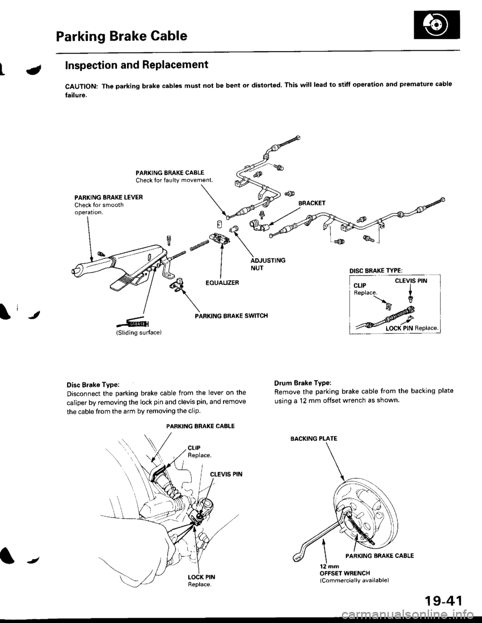
Parking Brake Cable
LInspection and Replacement
CAUTION: The parking blake cables must not be bent or distorted. This will lead to stiff operation and premature cable
failure.
PARKING BRAKE CABLECheck for faulty movement.
PARKING BRAKE LEVERCheck for smoothoperation.
\i ,
EOUALIZER
PARKING BRAKE SWITCH
Disc Brake Type:
Disconnect the parking brake cable from the lever on the
caliper by removing the lock pin and clevis pin, and remove
the cable from the arm by removing the clip
CLEVIS PIN
Drum Brake Type:
Remove the parking brake cable from the backing plate
using a 12 mm offset wrench as shown.
12 mmOFFSET WRENCH(Commercially available)
DISC BRAKE TYPE:
CLEVIS PIN
PARKING ERAKE CABLE
{tt
BACKING PLATE
/
19-41
Page 1196 of 2189
L-
t
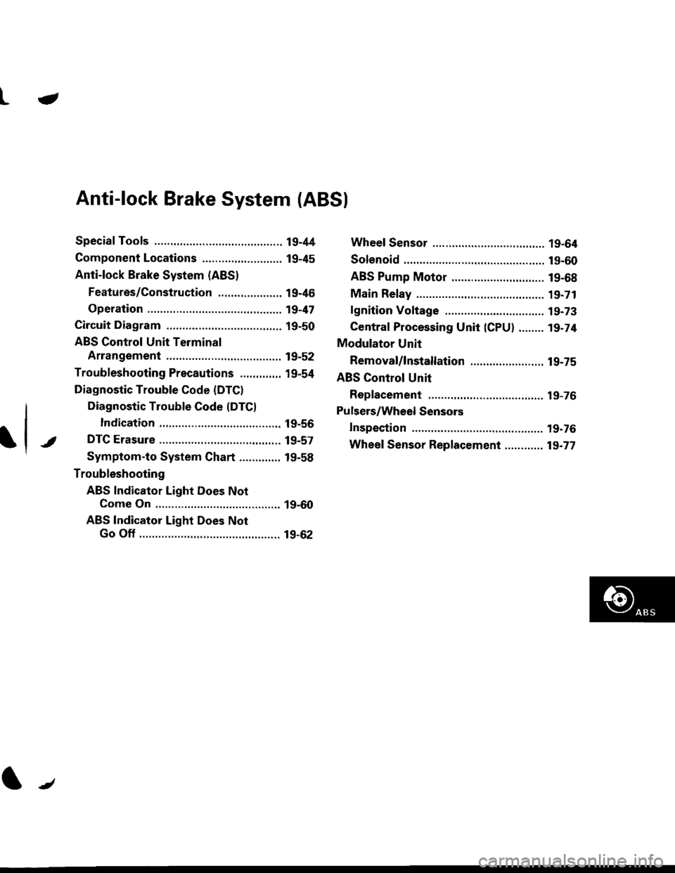
Anti-lock Brake System (ABSI
Special Tools ............. 19-44
Component Locations ......................... 19-45
Anti-lock Brake System (ABS)
Features/Construction ..................., 19-46
Operation ............... 19-47
Circuit Diagram ......... 19-50
ABS Control Unit Terminal
Arrangement ......... 19-52
Troubleshooting Precautions ............. 19-54
Diagnostic Trouble Code (DTCI
Diagnostic Trouble Gode (DTCI
Indication ........... 19-56
DTC Erasure ........... 19-57
Symptom-to System Chart ............. 19-58
Troubleshooting
ABS Indicator Light Does Not
Come On ............ 19-60
ABS Indicator Light Does Not
Go Off ............................................ 19-62
Wheel Sensor ........ 19-64
Solenoid ................. 19-60
ABS Pump Motor ............................. 19-68
Main Relay ............. 19-71
lgnition Voltage .... 19-73
Central Processing Unit {CPU} ........ 19-74
Modulator Unit
Removal/lnstallation ....................... 19-75
ABS Control Unit
Replacement ......... 19-76
Pulsers/Wheel Sensors
Inspection .............. 19-76
Wheel Sensor Replacement ............ 19-77
t/
Page 1199 of 2189
Anti-lock Brake System (ABSI
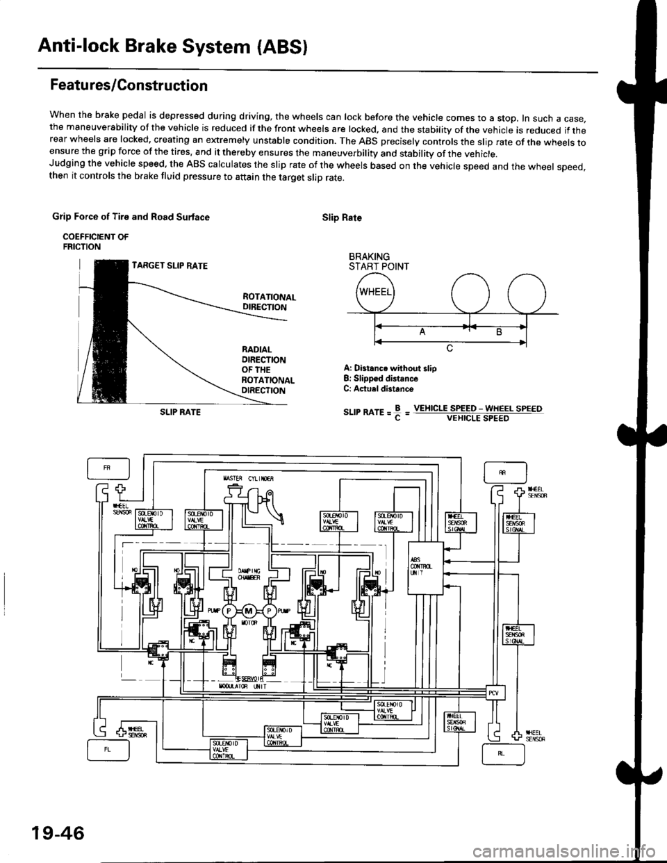
Featu res/Construction
When the brake pedal is depressed during driving, the wheels can lock before the vehicle comes to a stop, In such a case,the maneuverability of the vehicle is reduced if the front wheels are locked, and the stability of the vehicle is reduced if therear wheels are locked, creating an extremely unstable condition. The ABS precisely controls the slip rate of the wheels toensure the grip force of the tires. and it thereby ensures the maneuverbility and stability of the vehicle.Judging the vehicle speed. the ABS calculates the slip rate of the wheels based on the vehicle speed and the wheel speed,then it controls the brake fluid pressure to attain the target slip rate.
Grip Force of Tire and Road Surlace
COEFFICIENT OFFRICTION
TARGET SLIP RATE
Slip Rate
BRAKINGSTART POINT
ROTATIONALDIRECTION
RADIALDIRECTIONOF THEROTATIONALOIRECTION
A: Distance without slio8: Slippsd distanceC: Actuel distance
sr-rrmre=f=SLIP RATEVEIIICLE SPEED - WHEEL SPEEOVEHICLE SPEED
19-46
Page 1201 of 2189
Anti-lock Brake System {ABS)
Operation (cont'dl
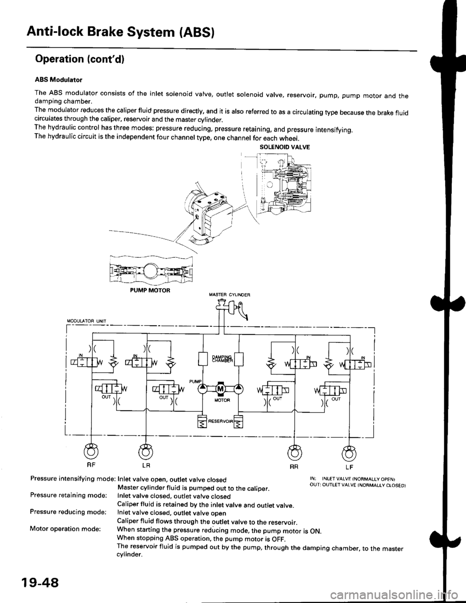
ABS Modulator
The ABS modulator consists of the inlet solenoid valve, outlet solenoid valve, reservoir, pump, pump motor and thedamping chamber.
The modulator reduces the caliper fluid pressure directly, and it is also referred to as a circulating type because the brake fluidcirculates through the caliper, reservoir and the master cylinder.The hydraulic control has three modes: pressure reducing, pressure retaining, and pressure intensifying.The hydraulic circuit is the independent four channel type, one channel for each wheel.
RF LR
Pressure intensifying mode: Inlet valve open, outlet valve closed
Pressure retaining mode:
Pressure reducing mode:
Motor operation mode:
rN: INLETVALVE {NORMALtY OpENIOUT: OUTIET VALVE {NORMALIY CTOSED)Master cylinder fluid is pumped out to the caliDer.Inlet valve closed, outlet valve closedCaliper fluid is retained by the inlet valve and outlet valve.Inlet valve closed, outlet valve oDenCaliper fluid flows through the outlet valve to the reservoir.When starting the pressure reducing mode, the pump motor is ON.When stopping ABS operation, the pump motor is OFF.The reservoir fluid is pumped out by the pump, through the damping chamber, to the mastercvlinder.
PUMP MOTOR
19-48
Page 1233 of 2189
l}
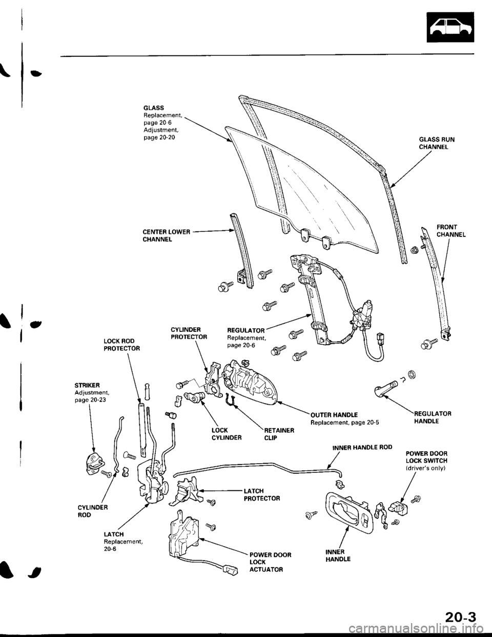
GLASSReplacement,page 20 6Adiustment,page 20-20GLASS RUNCHANNEL
CENTER LOWERCHANNEL
eCYLINDERPBOTECTORREGULATORReplacement,page 20-6LOCK RODPROTECTOR
STRIKER 'Adjustment, llpage 20-23
tt t[
#-l|r&
/h)
/Y
LOCKCYLINOERRETAINERCLIP
^o
?'2'
ourER HANoLE
ecuLaron
HANOLE
POWER DOORLOCK SwlTCH(driver's only)
Replacement, page 20-5
INNEN HANDLE ROD
LATCHPROIECTOR
-) /
s/
*Nqd'
/ -"-/
tt\
. '\
It
INNERHANDLE
20-3
Page 1235 of 2189
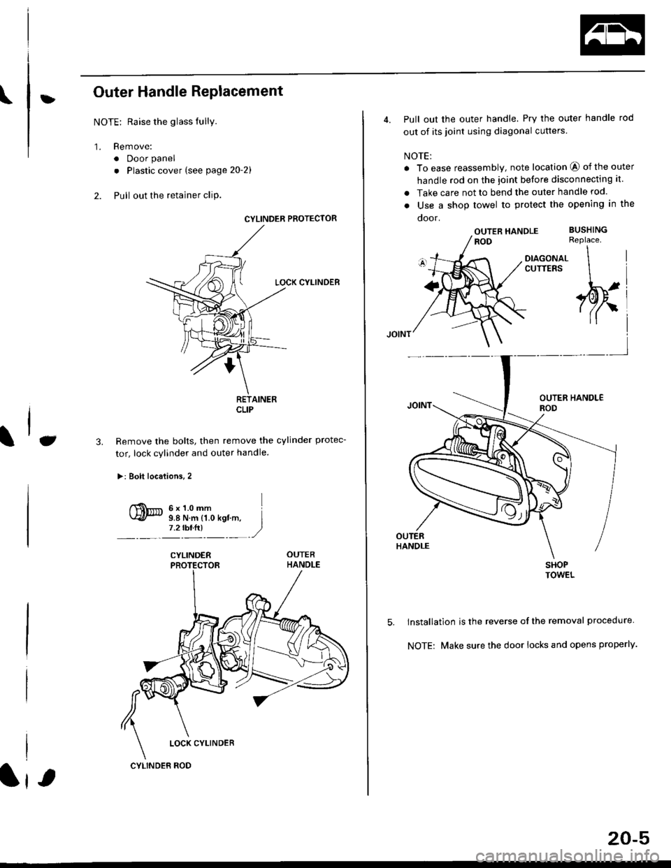
\:Outer Handle Replacement
NOTE: Raise the glass fully.
'1. Remove:
. Door panel
. Plastic cover (see page 2o-21
2. Pull out the retainer cliP.
6x1.omm Ii.e N.. tr.o rgf.-, I7.2 rbr.fi) ,2
C3.
CYLINDER PROTECTOR
LOCK CYLINDEB
RETAINERCLIP
Remove the bolts, then remove the cylinder protec-
tor, lock cylinder and outer handle.
>: Bolt locaiions,2
CYLINDER
LOCK CYLINDER
CYLINDER ROD
20-5
4. Pull out the outer handle. Pry the outer handle rod
out of its joint using diagonal cutters
NOTE:
a To ease reassembly, note location @ of the outer
handle rod on the joint before disconnecting it.
. Take care not to bend the outer handle rod.
o Use a shop towel to protect the opening in the
ooor.
OUTER HANDLEROD
DIAGONALCUTTERS
SHOPTOWEL
lnstallation is the reverse of the removal procedure
NOTE: Make sure the door locks and opens properly.
BUSHINGReplace.
\
,w.
5.
i4'