service HONDA CIVIC 2002 7.G Owners Manual
[x] Cancel search | Manufacturer: HONDA, Model Year: 2002, Model line: CIVIC, Model: HONDA CIVIC 2002 7.GPages: 1139, PDF Size: 28.19 MB
Page 826 of 1139
System Charging
Air conditioning refrigerant or lubricant vapor
can irritate your eyes, nose, or throat.
Be carefulwhen connecting service equipment.
Do not breathe refrigerant or vapor,
Use only service equipment that is U.L.'listed and is
certified to meet the requirements of SAE J2210 to
remove HFC-134a {R-134a) from the air conditioning
system.
lf accidental system discharge occurs, ventilate the
work area before resuming service
Additional health and safety information may be
obtained from the refrigerant and lubricant
manufacturers.
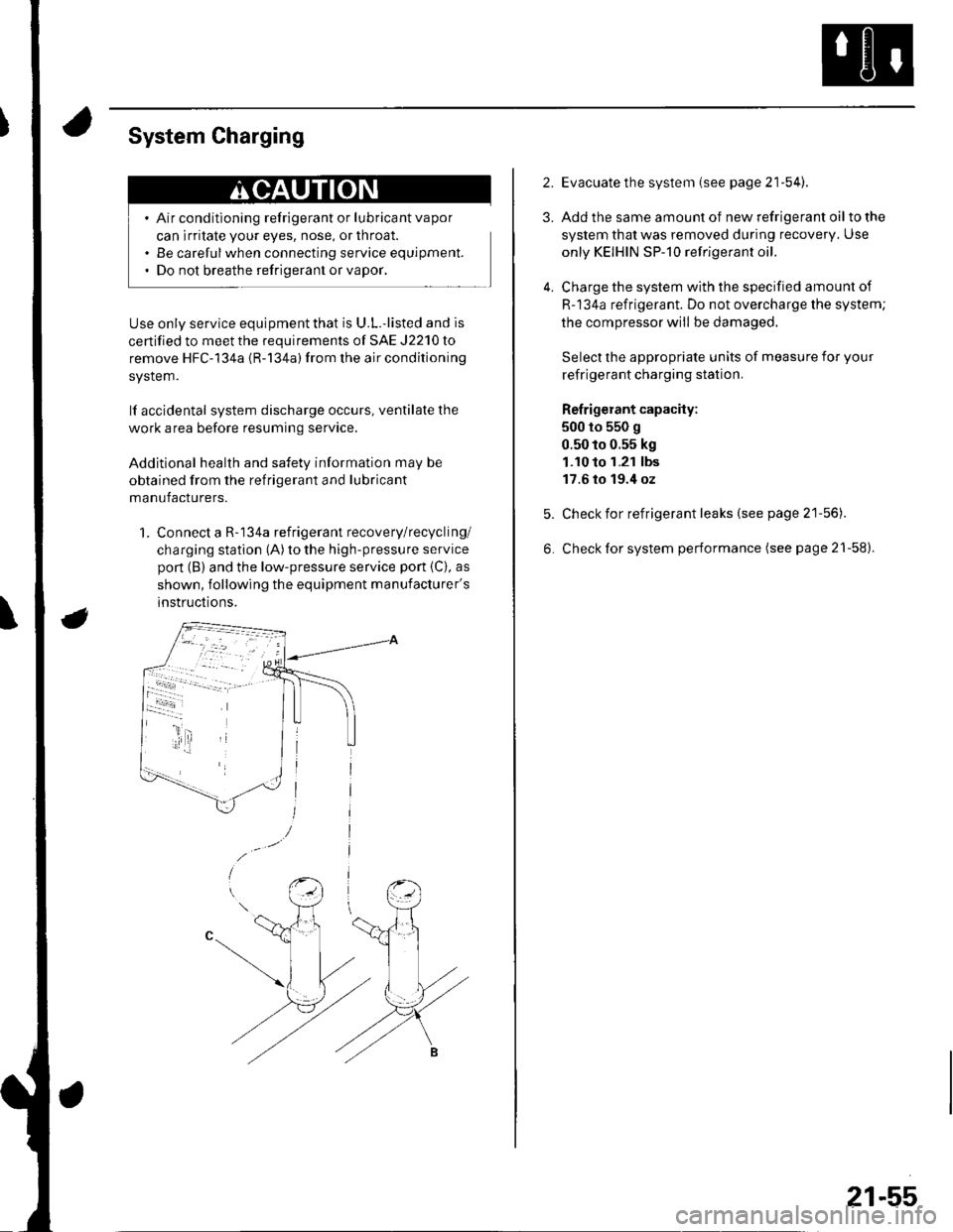
1. Connect a R-134a refrigerant recovery/recycling/
charging station (A) to the high-pressure service
pon (B) and the low-pressure service port {C), as
shown, following the equipment manufacturer's
instructions.
2.
3.
4.
Evacuate the system (see page 21'54).
Add the same amount of new refrigerant oil to the
system that was removed during recovery. Use
only KEIHIN SP-10 refrigerant oil.
Charge the system with the specified amount of
R-134a refrigerant. Do not overcharge the system;
the compressor will be damaged.
Select the appropriate units of measure for your
refrigerant charging station.
Refrigerant capacity:
500 to 550 g
0.50 to 0.55 kg
1.10 to 1.21 lbs
17.6 to 19.4 oz
Check for refrigerant leaks (see page 21'56).
Check for system performance (see page 21-58).
21-55
Page 827 of 1139
Heating and Air Conditioning
Refrigerant Leak Test
Special Tool Required
Leak detector, Honda Tool and Equipment YGK-H-10PM
commerciallv available
Compressed air mixed with R-134a forms a
combustible vapor.
The vapor can burn or explode causing serious
injury.
Never use compressed air to pressure test
R-134a service equipment or vehicle air
conditioning system.
Air conditioning refrigerant or lubricant vapor
can irritate your eyes, nose, or throat.
Be carefulwhen connecting service equipment.
Do not breathe refrigerant or vapor
Use only service equipment that is U.L.-listed and is
certiified to meet the requirements of SAE J2210 to
remove HFC-134a (R-134a) from the air conditioning
system.
lf accidental system discharge occurs, ventilate the
work area before resuming service.
R-134a service equipment or vehicle air conditioning
systems should not be pressure tested or leak tested
with compressed air.
Additional health and safety information may be
obtained from the refrigerant and lubricant
manufacturers.
21-56
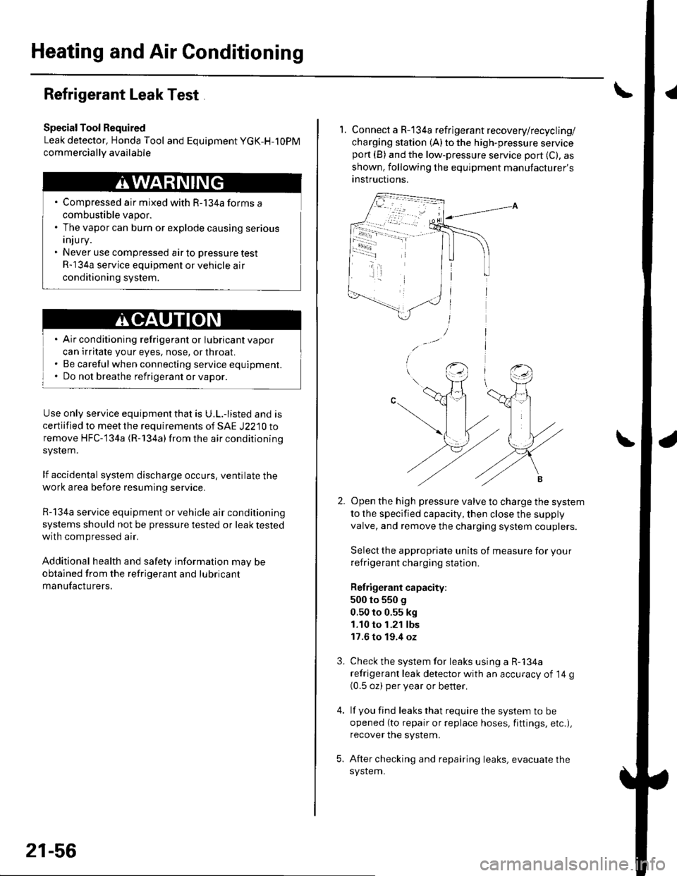
1. Connect a R-134a refrigerant recovery/recycling/
charging station (A) to the high-pressure serviceport (B) and the low-pressure service port (C), as
shown, following the equipment manufacturer's
anstructions.
Open the high pressure valve to charge the system
to the specified capacity, then close the supply
valve, and remove the charging system couplers.
Select the appropriate units of measure for your
refrigerant charging station.
Refrigerant capacity:
500 to 550 g
0.50 to 0.55 kg
1.10 to 1.21 lbs
17.6 to 19.4 oz
Check the system for leaks using a R-134a
refrigerant leak detector with an accuracy of 14 g(0.5 oz) per year or better.
lf you find leaks that require the system to be
opened (to repair or replace hoses, fittings, etc.),
recover the system.
After checking and repairing leaks, evacuate the
system.
3.
Page 829 of 1139
Heating and Air Conditioning
A/C System Tests (cont'd)
1.
Performance Test
Air conditioning refrigerant or lubricant vapor
can irritate your eyes, nose, or throar.
Be carefulwhen connecting service equipment.
Do not breathe refrigerant or vapor.
The performance test will help determine if the air
conditioner system is operating within specifications.
Use only service equipment that is U.L.-listed and is
cenified to meet the requirements of SAE J2210 toremove HFC-134a (R-134alfrom the air conditioning
system.
lf accidental system discharge occurs, ventilate the
work area before resuming service
R-134a service equipment or vehicle air conditioning
systems should not be pressure tested or leak testedwith compressed air.
Additional health and safety information may be
obtained from the refrigerant and lubricant
manufacturers.
Connect a R-134a refrigerant recover/recycling/
charging station to the high-pressure service port
and the low-pressure service port, following the
equipment manufacturer's instructions.
Determine the relative humidity and air
Iemperaru re.
' Compressed air mixed with R-134a forms a
combustible vapor.. The vapor can burn or explode causing serious
Injury.. Never use compressed air to pressure test
R-134a service equipment or vehicle air
conditioning systems.
21-58
4.
Open the glove box. Remove both glove box stops,
then let the glove box hang down (see page 20-63).
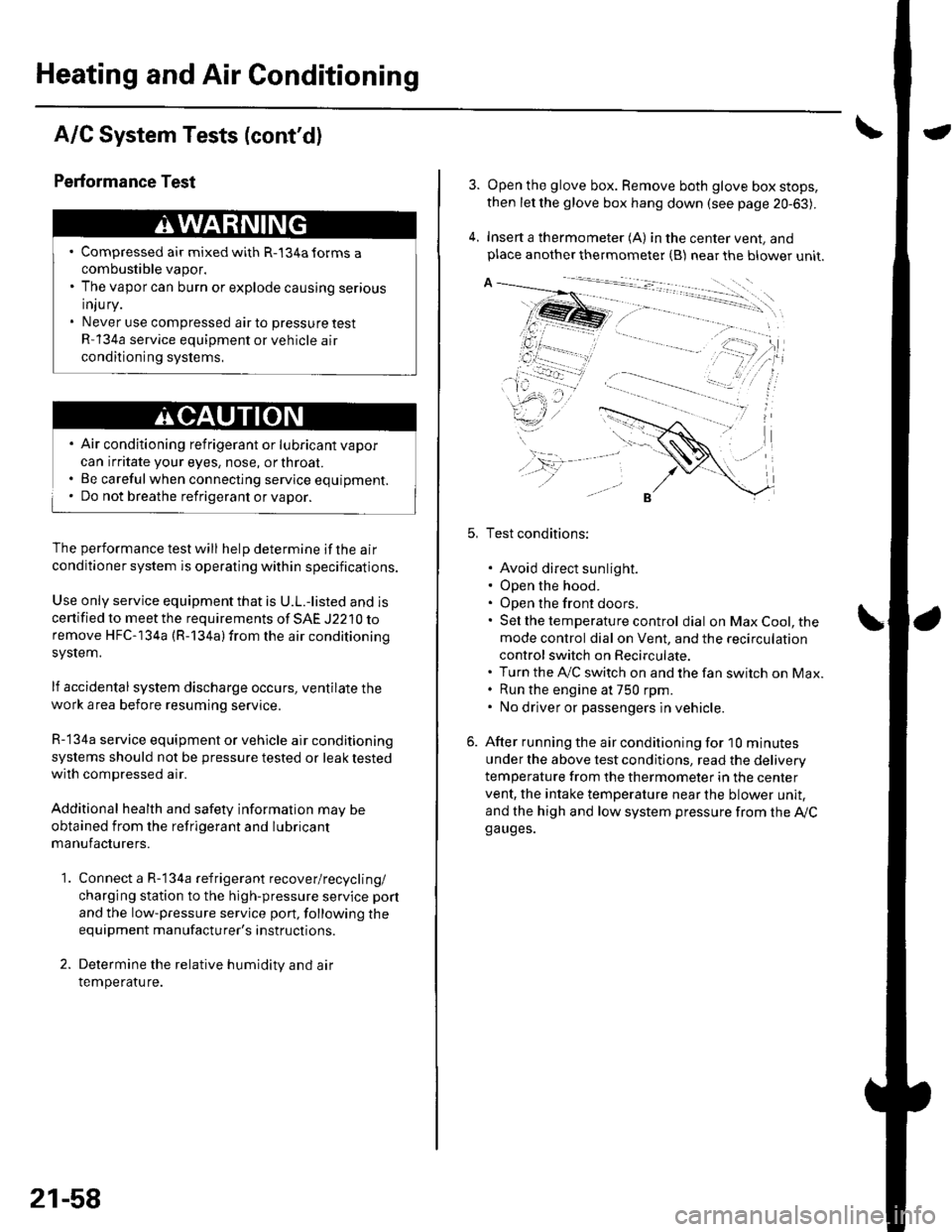
Insert a thermometer (A) in the center vent, andplace another thermometer {B) near the blower unit.
Test conditions:
. Avoid direct sunlight.. Open the hood.. Open the front doors.. Sel the temperature control dial on Max Cool, the
mode control dial on Vent, and the recirculation
control switch on Recirculate.. Turn the A,/C switch on and the fan switch on Max.. Run the engine at 750 rpm.. No driver or passengers in vehicle.
After running the air conditioning for I0 minutes
under the above test conditjons, read the delivery
temperature from the thermometer in the center
vent, the intake temperature near the blower unit,
and the high and low system pressure from the Ay'Cga uges.
Page 833 of 1139
Body Electrical
SpecialTools
@
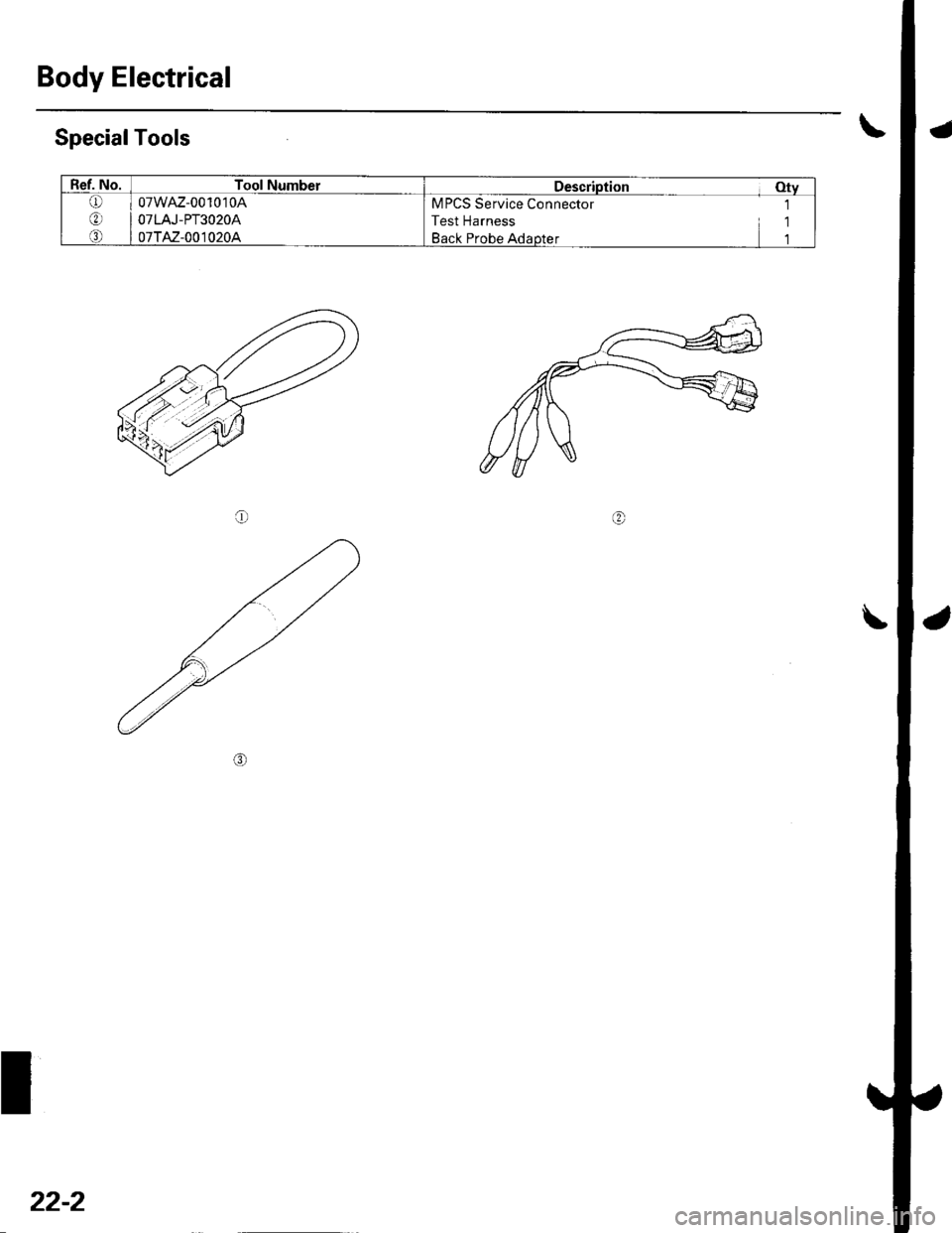
Ref. No.Tool NumberDescription Otv
Q)
o)
o
07wAz-001010A
O7 LAJ - PT3 O 2OA
07TAz-001020A
MPCS Service Connector 1
Test Harness 1
Back Probe Adaotet 1
22-2
Page 876 of 1139
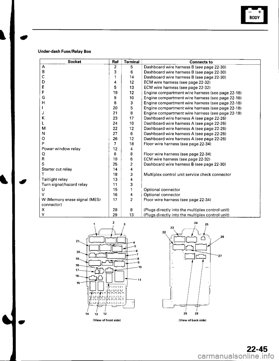
Under-dash Fuse/Relay Box
SocketRefTerminal Connects to
B
c
D
E
F
G
H
J
K
M
N
o
P
Power window relay
o
R
S
Starter cut relay
T
Taillight relay
Turn signal/hazard relay
U
W (Memory erase signal (MES)
connector)
X
Y
2
3
1
5
19
9
I
20
24
22
27
26
7
6
10
25
14
18
11
l5
to
17
28
5
6
14
13
12
10
3
:
11'10
1:
.o^
;;
4
8
2
i
nl
al
lt
2
Dashboard wire harness B {see page 22-30)
Dashboard wire harness B {see page 22-30)
Dashboard wire harness B (see page 22-30)
ECM wire harness (see page 22-32)
ECI\4 wire harness (see page 22-32)
Engine compartment wire harness (see page 22-'l8l
Engine compartment wire harness (se e page 22-181
Engine compartment wire harness (see page 22-18)
Engine compartment wire harness (se e page 22-18)
Engine compartment wire harness (see page 22-18)
Dashboard wire harness A (see page 22-26)
Dashboard wire harness A (see page 22-26)
Dashboard wire harness A (see page 22-26)
Dashboard wire harness A (see page 22-26)
Dashboard wire harness A (see page 22-26)
Floor wire harness (see page 22-34)
Floor wire harness (see page 22-34)
ECM wire harness (see page 22-32)
Dashboard wire harness B (see page 22-30)
Multiplex control unit service check connector
Optional connector
Optional connector
Floor wire harness (see page 22-34)
{Plugs directly into the multiplex control(Pluqs directlv into the multiDlex control
unat)
unrl)
I
13
tn--rlI U LI L.] L.Jh--n-UL]L]UL]
I] L] L] LI L]
!3 12
22-45
Page 880 of 1139
Under-dash Fuse/Relay Box
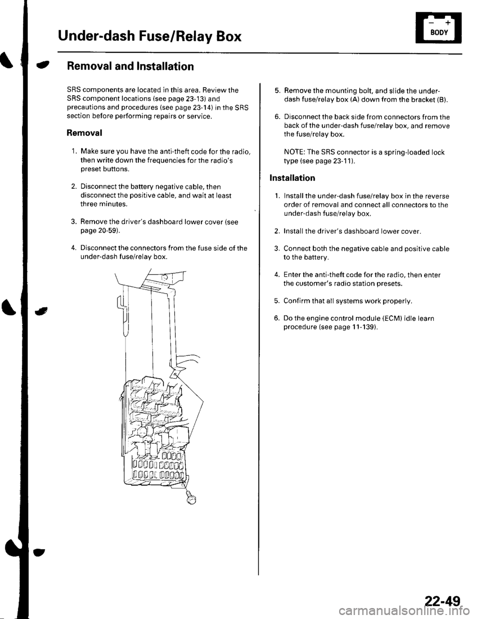
Removal and Installation
SRS components are located in this area. Review the
SRS component locations {see page 23-13) andprecautions and procedures (see page 23-14) in the SRS
section before performing repairs or service.
Removal
1. Make sure you have the anti-theft code for the radio,
then write down the frequencies for the radio's
preset buttons.
2. Disconnectthe battery negative cable, then
disconnect the positive cable, and wait at least
three minutes.
3. Remove the driver's dashboard lower cover (see
page 20-59).
4. Disconnect the connectors from the fuse side of the
under-dash fuse/relay box.
5. Remove the mounting bolt, and slide the under-
dash fuse/relay box (A) down from the bracket {B).
6. Disconnect the back side from connectors from the
back of the under-dash fuse/relay box, and remove
the fuse/relay box.
NOTE:The SRS connector is a spring-loaded lock
type (see page 23-1 1).
lnstallation
1. Installthe under-dash fuse/relay box in the reverse
order of removal and connect all connectors to the
under-dash fuse/relay box.
2. Installthe driver's dashboard lower cover.
3. Connect both the negative cable and positive cable
to the battery.
4. Enter the anti-theft code for the radio, then enter
the customer's radio station presets.
5. Confirm that all systems work properly,
6. Do the engine control module (ECM) idle learn
procedure (see page 11-139).
22-49
Page 884 of 1139
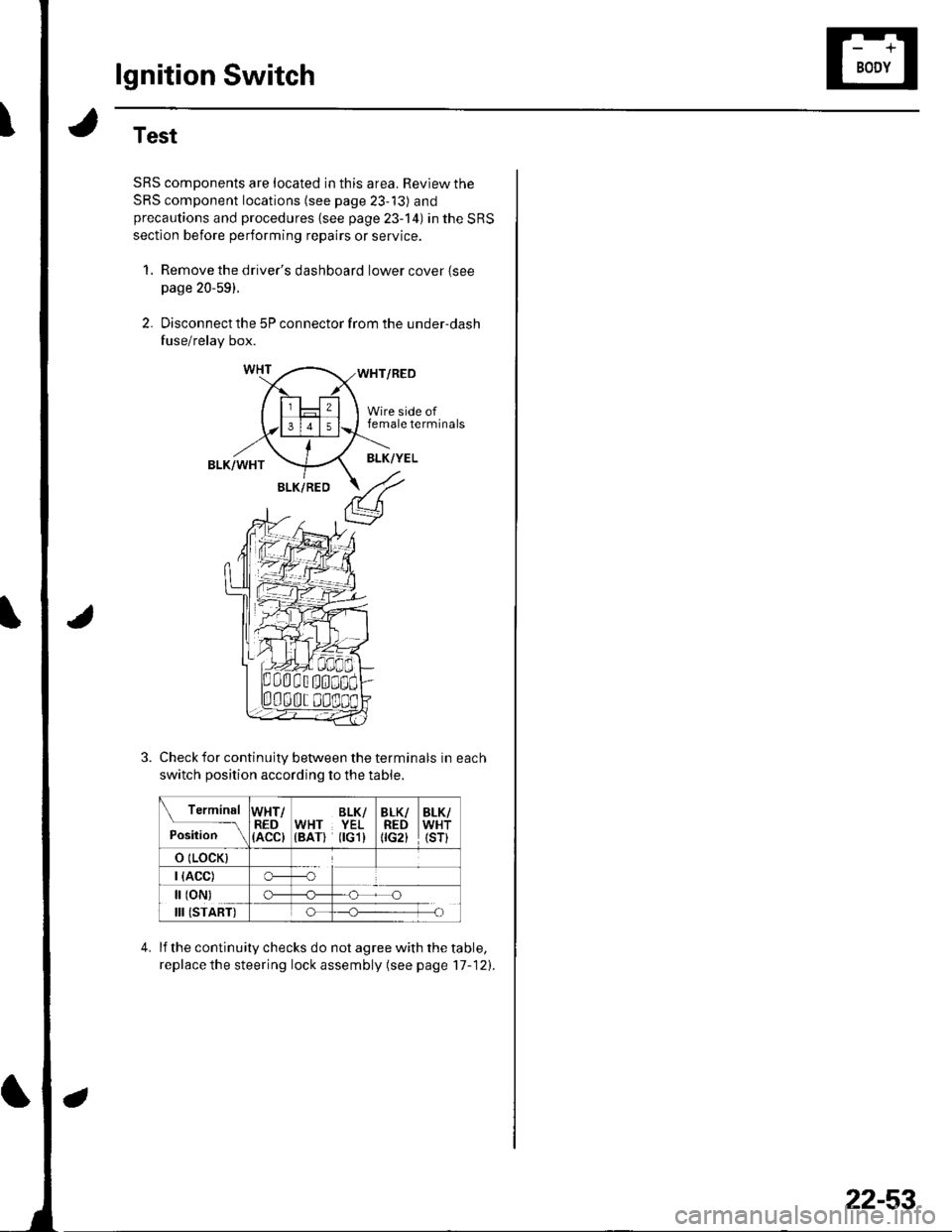
lgnition Switch
Test
SRS components are located in this area. Review the
SRS component locations (see page 23-13) andprecautions and procedures {see page 23-'l4) in the SRS
section before performing repairs or service.
1, Remove the driver's dashboard lower cover {seepage 20-59).
2. Disconnect the 5P connector from the under-dash
fuse/relay box.
WHT/RED
Wire side offemale terminals
BLK/WHTBLK/YEL
BLK/RED
Check for continuity between the terminals in each
switch position according to the table.
Terminal
p.J,i""-\
WHT/RED(ACC)
BLK/WHT YEL(BAT) flGl)
BLK/REDtrc2t
BLK/WHT(sr)
o (LocK)
| (ACC)o---o
[ (oN)
III (START)
c)-_H
o_H
lf the continuity checks do not agree with the table,
replace the steering lock assembly (see page'17-121.
22-53
Page 1010 of 1139
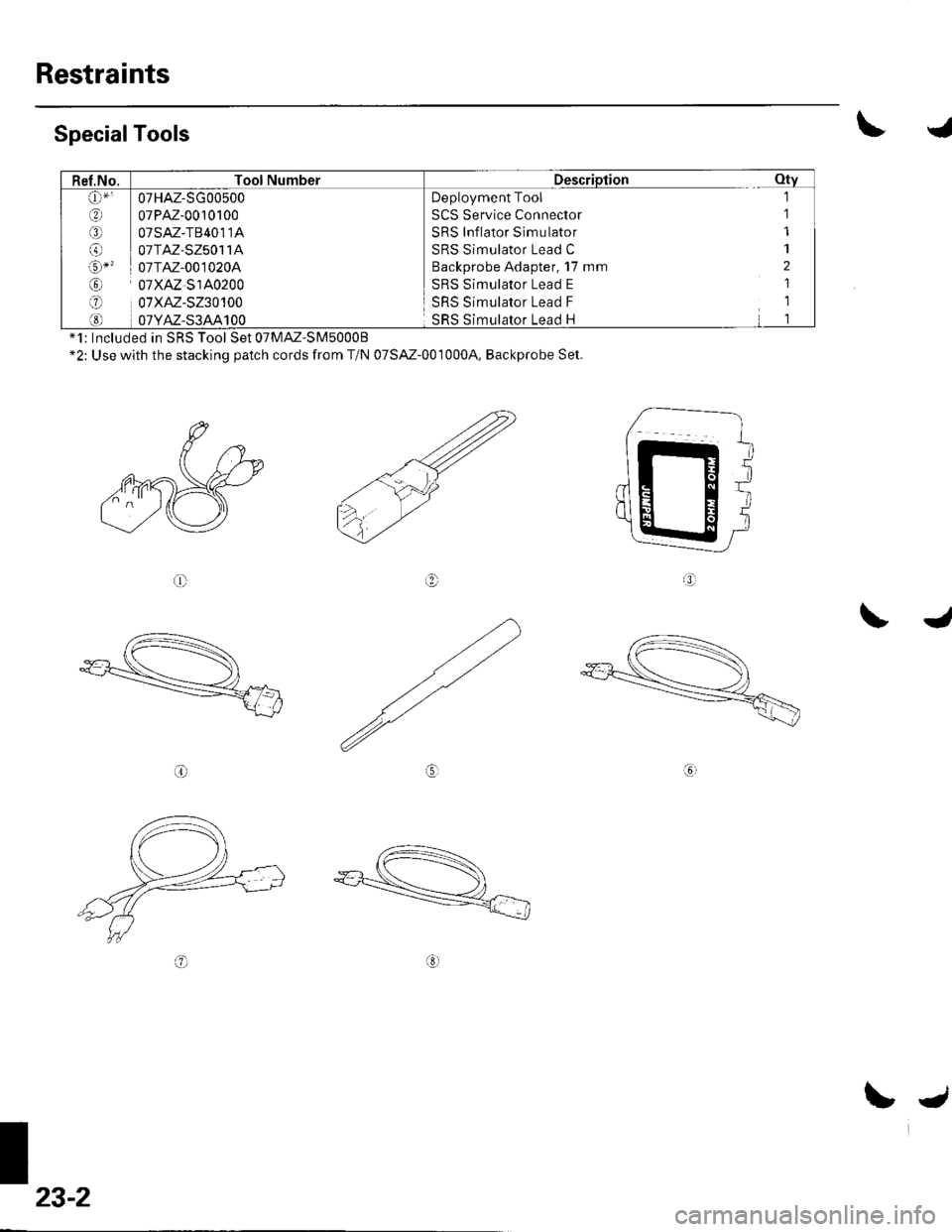
Restraints
\SpecialTools
@
*1: Included in SRS Tool Set 07MM'SM50008*2: Use with the stacking patch cords from T/N 07SAZ-0010004, Backprobe Set.
oo
ro
\J
Gl
' 07HAZ-SG00500Deployment Tool
SCS Service Connector
SRS Inflator Sim u lator
SRS Simulator Lead C
Backprobe Adapter, 17 mm
SRS Simulator Lead E
SRS Simulator Lead F
8t oTPM-oo101oo
€ oTsM-TB4o114
O oTTM-sz5o114
o-' 07TM-0010204
@ o7xAz-s140200-1 07xAz-s230100
SRS Simulator Lead H
23-2
L.
Page 1012 of 1139
Seat Belts
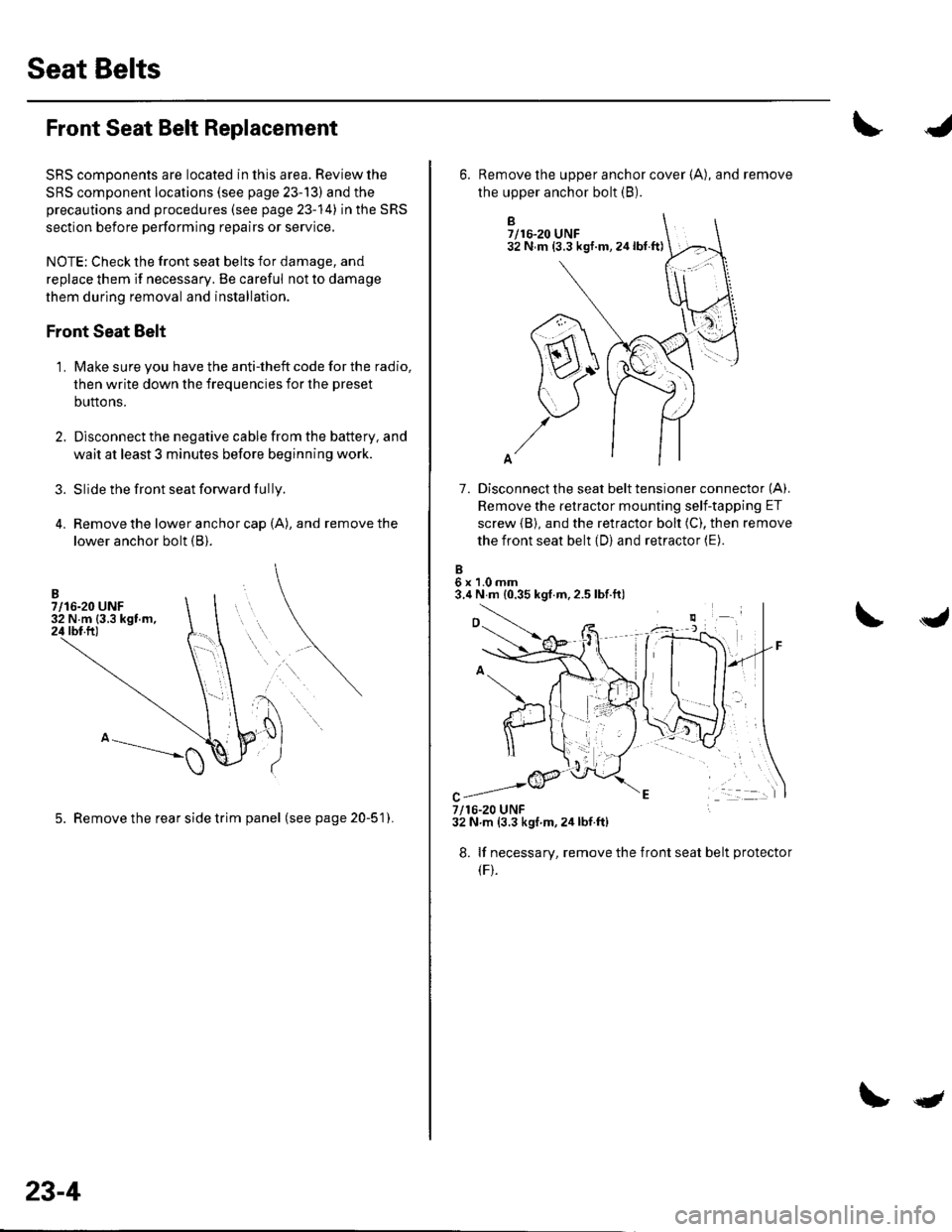
Front Seat Belt Replacement
SRS comDonents are located in this area. Review the
SRS component locations (see page 23-13) and the
precautions and procedures (see page 23-14) in the SRS
section before performing repairs or service,
NOTE: Check the front seat belts for damage, and
replace them if necessary. Be careful not to damage
them during removal and installation.
Front Seat Belt
Make sure you have the anti-theft code for the radio,
then write down the frequencies for the preset
buttons.
Disconnect the negative cable from the battery, and
wait at least 3 minutes before beginning work.
Slide the front seat forward fully.
Remove the lower anchor cap (A), and remove the
lower anchor bolt (B).
3.
1.
5. Remove the rear side trim panel (seepage20-51).
23-4
qt
B7/16-20 UNF32 N m (3.3 kgf.m,24lbt.ft)
7. Disconnect the seat belt tensioner connector (A).
Remove the retractor mounting self-tapping ET
screw {B), and the retractor bolt (C), then remove
the front seat belt (D) and retractor (E).
6x1.0mm3.4 N m {0.35 kgf.m,2.5 lbf.ft)
6. Remove the upper anchor cover {A), and remove
the upper anchor bolt (B).
7/16-20 UNF32 N.m (3.3 kgf m,2ir lbf.ft)
8. lf necessary, remove the
(F).
front seat belt protecto
Page 1017 of 1139
I
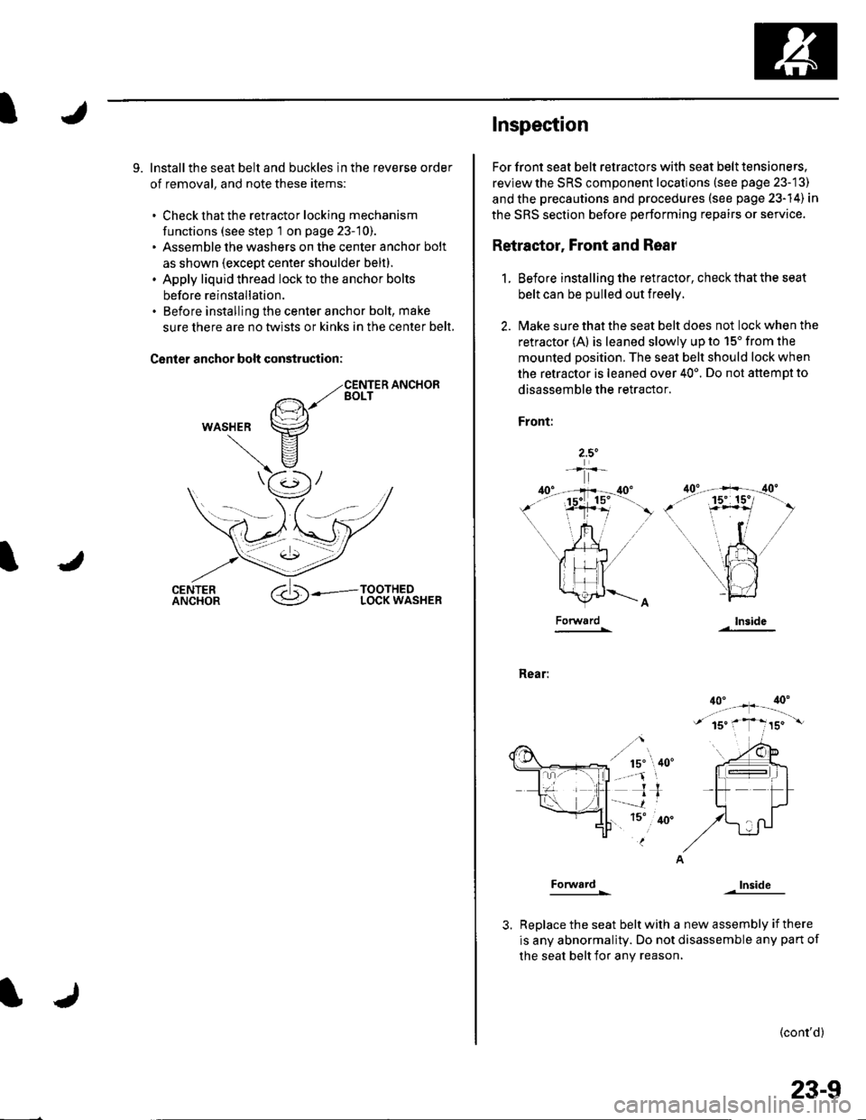
9. lnstallthe seat belt and buckles in the reverse order
of removal, and note these items:
. Check that the retractor locking mechanism
functions (see step 1 on page 23-10).. Assemble the washers on the center anchor bolt
as shown (except center shoulder belt).. Apply liquid thread lock to the anchor bolts
before reinstallation.. Before installing the center anchor bolt, make
sure there are no twlsts or kinks in the center belt,
Canler anchor bolt construction:
WASHER
Inspec'tion
For front seat belt retractors with seat belt tensioners.
reviewthe SRS component locations (see page 23-13)
and the precautions and procedures (see psge 23-14) in
the SRS section before performing repairs or service.
Retractor, Front and Rear
1. Before installing the retractor, check that the seat
belt can be pulled out freely.
2. l\4ake sure that the seat belt does not lock when the
retractor (A) is leaned slowly up to 15'from the
mounted position. The seat belt should lock when
the retractor is leaned over 40'. Do not attemDt to
disassemble the retractor.
Front:
Rear:
Forward
Forward
lnside
Inside
Replace the seat belt with a new assembly if there
is any abnormality. Do not disassemble any pan of
the seat belt for any reason,
(cont'd)
23-9