service HONDA CIVIC 2002 7.G Manual PDF
[x] Cancel search | Manufacturer: HONDA, Model Year: 2002, Model line: CIVIC, Model: HONDA CIVIC 2002 7.GPages: 1139, PDF Size: 28.19 MB
Page 615 of 1139
Conventional Brake Components
Rear Brake Pads Inspection and Replacement
Frequent inhalation of brake pad dust, regardless ofmaterial composition, could be hazardous to your
hea hh.. Avoid breathing dust particles.. Never use an air hose or brush to clean brake
assemblies, Use an OSHA-approved vacuum
cleaner.
Inspection
'1. Raise the rear of the vehicle, and support jt with
safety stands in the proper location (see page 1-8).Remove the rear wheels,
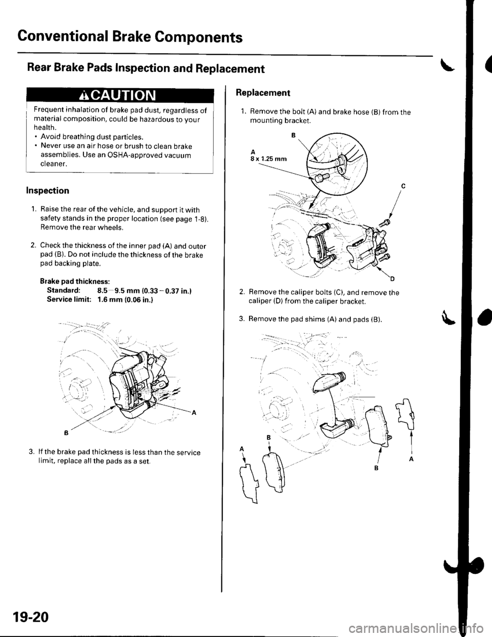
2. Check the thickness of the inner pad (A) andouterpad (B). Do not include the thickness of the brakepad backing plate.
Brake pad thickness:
Standard: 8.5 9.5 mm {0.33-0.37 in.}
Service limit: 1.6 mm (0.06 in.)
B -::--
lf the brake pad thickness is less than the servicelimit, replace allthe pads as a set.
3.
19-20
Replacement
1. Remove the bolt (A) and brake hose {B} from themounting bracket.
Remove the caliper bolts (C), and remove thecaliper (D) from the caliper bracket.
Remove the pad shims (A) and pads (B).3.
A
t{
\
tIA
A
\
r\
))
\
Page 617 of 1139
Conventional Brake Components
Rear Brake Disc Inspection
Runout
1. Raise the rear of the vehicle, and support it with
safety stands in the proper location (see page 1-8).Remove the rear wheels,
2. Remove the brake pads (see page 19-20).
3. Inspect the disc surface for damage and cracks.
Clean the disc thoroughly, and remove all rust,
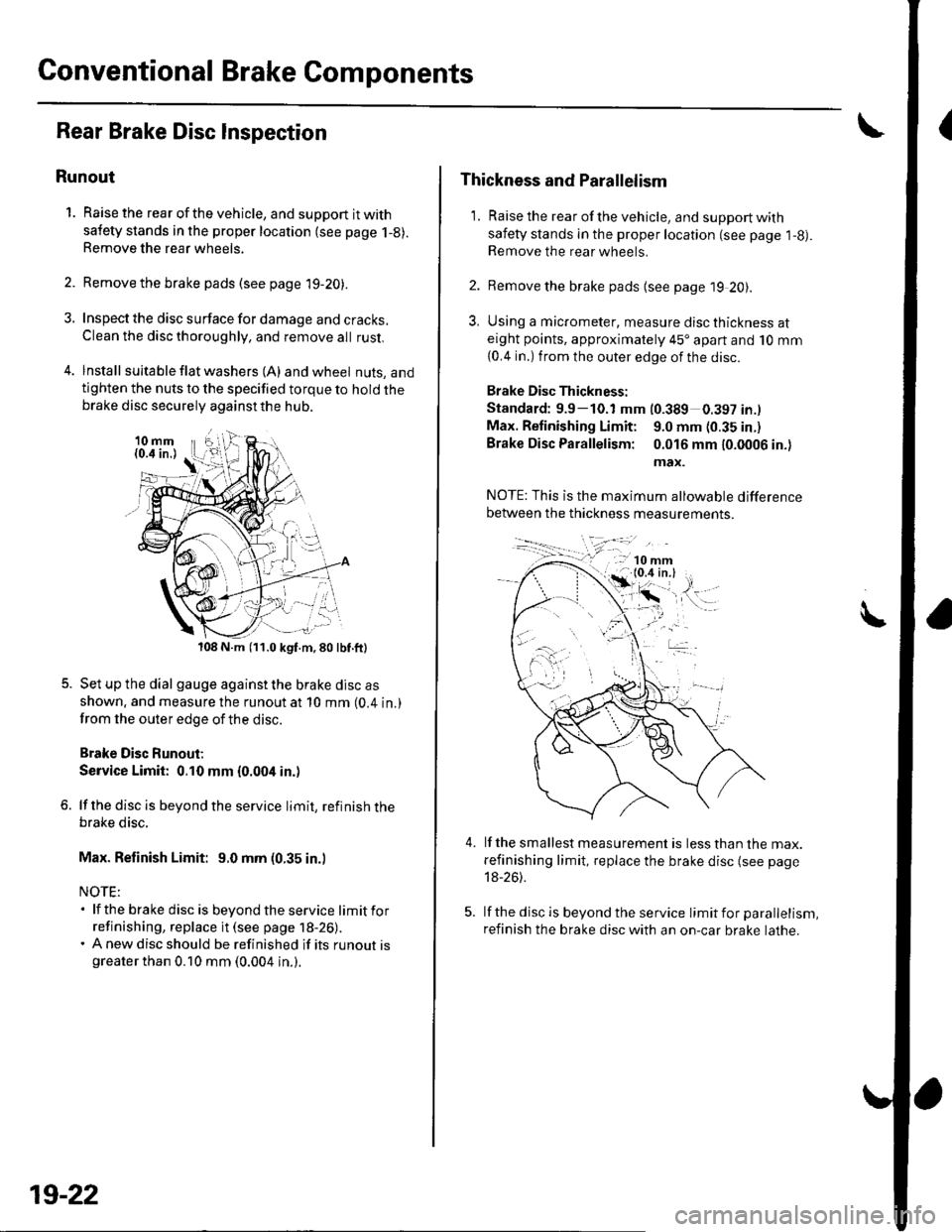
4. lnstall suita ble f lat washers (A) and wheel nuts, andtighten the nuts to the specified torque to hold thebrake disc securely against the hub.
108 N.m (11.0 kgf.m,80lbf.ft)
Set up the dial gauge against the brake disc as
shown. and measure the runout at 10 mm (0.4 in.)
from the outer edge of the disc.
Brake Disc Runout;
Service Limit: 0.10 mm {0.004 in.)
lf the disc is beyond the service limit, refinish thebrake disc.
Max. Refinish Limit: 9.0 mm (0.35 in.)
NOTE:. lf the brake disc is beyondtheservice limitfor
refinishing, replace it (see page 18-26).. A new disc should be refinished if its runout isgreater than 0.10 mm (0.004 in.).
19-22
Thickness and Parallelism
1. Raise the rear of the vehicle, and support with
safety stands in the proper location (see page l-g).Remove the rear wheels.
2. Remove the brake pads {see page 19 20).
3, Using a micrometer, measure disc thickness ateight points, approximately 45'apart and 10 mm
{0.4 in.) from the outer edge of the disc.
Brake Disc Thickness:
Standard: 9.9-10.1 mm (0.389 0.397 in.l
Max. Retinishing Limit: 9.0 mm (0.35 in.)
Brake Disc Parallelism: 0.016 mm 10.0006 in.)
max.
4.lf the smallest measurement is less than the max.
refinishing limit, replace the brake disc (see page
18-26).
lf the disc is beyond the service limit for parallelism,
refinish the brake disc with an on-car brake lathe.
Page 619 of 1139
Conventional Brake Components
{Brake Hoses and Lines Inspection
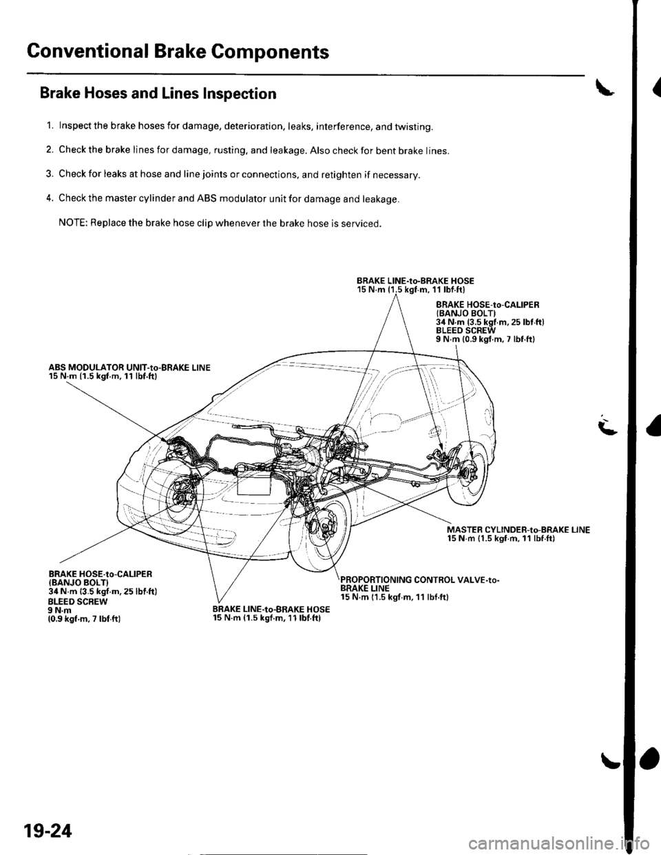
1. Inspect the brake hosesfordamage, deterioration, leaks, interference, andtwisting.
2. Check the brake lines for damage, rusting. and leakage. Also check for bent brake lines.
3. Check for leaks at hose and line joints or connections, and retighten if necessary.
4. Check the master cylinder and ABS modulator unit for damage and leakage.
NOTE: Replace the brake hose clip whenever the brake hose is serviced.
15 N.m (1.5 kgf.m, 11 lbf.ftl
ABS MODULATOR UNIT-Io-BRAKE LINE15 N.m {1.5 kgf m.11 lbf.ftl
BRAKE HOSE-to-CALIPERlBANJO BOLTI3il N.m {3.5 kgf.m.25 lbt'ft)BLEEO SCREW9 N.m {0.9 kgf.m,7 lbf.ftl
MASTER CYLINDEB-to-BRAKE LINE15 N m {1.5 kgt.m, ll lbf.ft)
CONTROL VALVE-to-
L
BRAKE HOSE.tO-CALIPER{BANJO BOLTI34 N.m {3.5 kgf.m, 25 lbl.ft)BLEED SCBEW9 N.m10.9 kgf.m, 7 lbf ft)
BRAKE LINE15 N.m 11.5 kgf m, 11 lbf.ft)
BRAKE LINE-Io-BRAKE HOSE15 N.m (1.5 kgf.m,11lbf.ftl
BRAKE LINE-to-BRAKE HOSE
t''/,i'i'
,/ ,l
t t,.. -)
19-24
Page 626 of 1139
ABS Components
General Troubleshooting Information (cont'd)
How to Troubleshoot ABS DTCs
The troubleshooting flowchart procedures assume that
the cause of the oroblem is still Dresent and the ABS
indicator is still on. Following the flowchart when the
ABS indicator does not come on can result in incorrect
diagnosis.
The connector illustrations show the female terminal
connectors with a single outline and the male terminal
connectors with a double outline.
1. Ouestion the customer about the conditions when
the problem occured, and try to reproduce the
same conditions for troubleshooting. Find out
when the ABS indicator came on, such as during
ABS control, after ABS control, when the vehicle
was at a certain speed, etc.
2. When the ABS indicator does not come on during
the test-drive, but troubleshooting is done based on
the DTC, check for loose connectors. poor terminal
contact, etc., before you start troubleshooting.
3. After troubleshooting, clear the DTC,disconnect the
Honda PGM Tester. and test-drive the vehicle.
Make sure the ABS indicator does not come on.
How to Retrieve ABS DTCs
Honda PGM Tester Method:
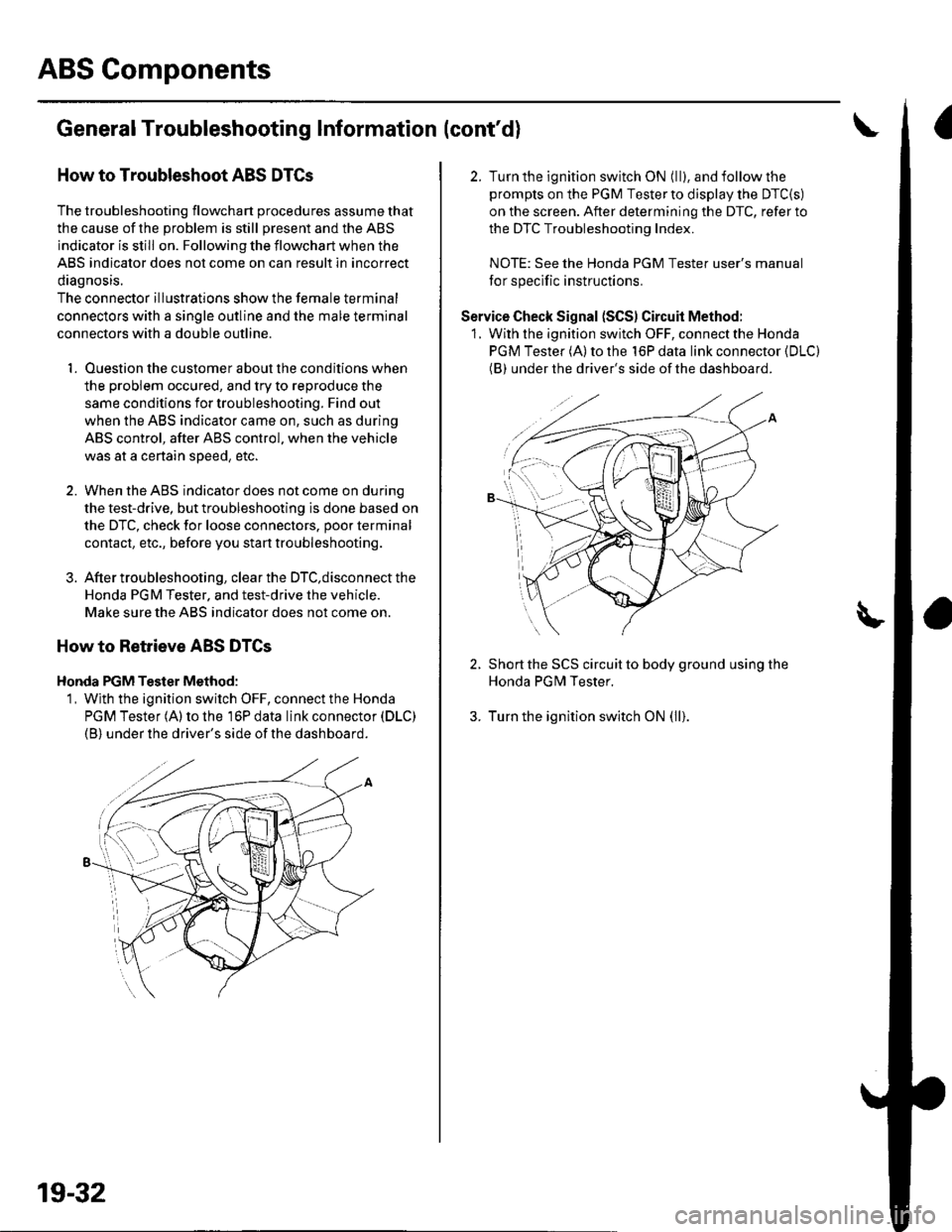
1, Wjth the ignition switch OFF, connect the Honda
PGM Tester (A) to the 16P data link connector (DLC)
(B) under the driver's side of the dashboard.
19-32
2. Turn the ignition switch ON (ll), and follow the
prompts on the PGM Tester to display the DTC{S)
on the screen. After determining the DTC, refer to
the DTC Troubleshooting Index.
NOTE: See the Honda PGM Tester user's manual
for specific instructions.
Service Check Signal (SCS) Circuit Method:
1. With the ignition switch OFF, connect the Honda
PGM Tester (A) to the 16P data link connector (DLC)
(BI under the driver's side of the dashboard.
2. Short the SCS circuit to body ground using the
Honda PGM Tester.
3. Turn the ignition switch ON (ll).
Page 709 of 1139
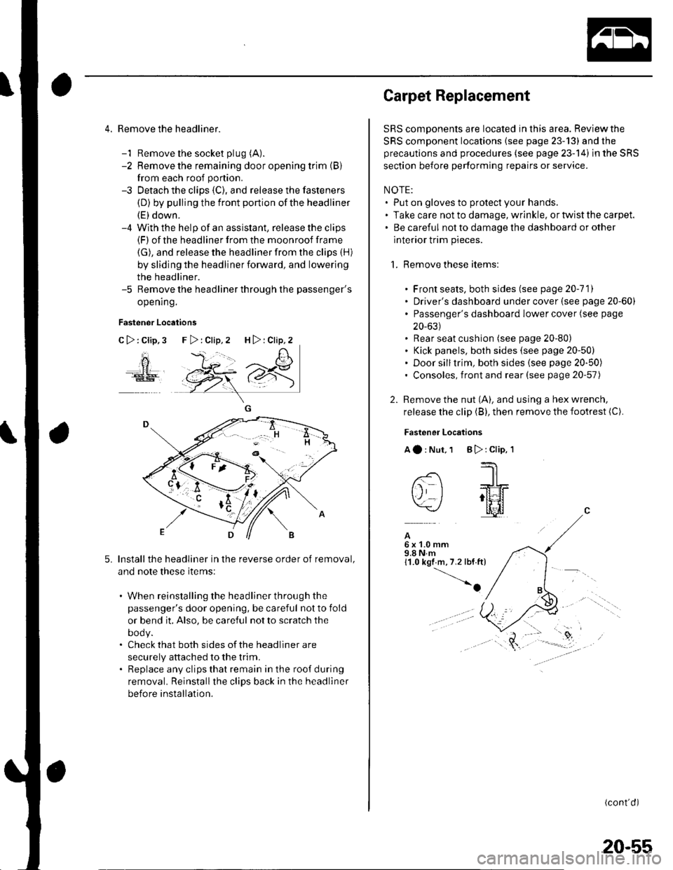
4. Remove the headliner.
-1 Remove the socket plug (A).
-2 Remove the remaining door opening trim {B}
from each roof portion.
-3 Detach the clips (C), and release the fasteners
(D) by pulling the front portion ofthe headliner
(E) down.-4 With the help of an assislant, release the clips(F) of the headliner from the moonroof frame
(G), and release the headliner from the clips (H)
by sliding the headliner forward, and lowering
the headliner.-5 Remove the headliner through the passenger's
opening.
Fastener Locations
C>:Clip,3
ao
5.Install the headliner in the reverse order of removal,
and note these items:
. When reinstalling the headliner through the
passenger's door opening, be careful not to fold
or bend it, Also, be careful not to scratch the
DOOy.. Check that both sides of the headliner are
securely attached to the trim.. Replace any clips that remain in the roof during
removal. Reinstallthe clips back in the headliner
before installation.
F>:Clip,2 H>:Clip,2
Carpet Replacement
SRS components are located in this area. Reviewthe
SRS component locations (see page 23-13) and the
precautions and procedures (see page 23-14) in the SRS
section before performing repairs or service.
NOTE:. Put on gloves to protect your hands.. Take care not to damage, wrinkle. or twist the carpet.. Be careful not to damage the dashboard or other
interior trim pieces.
1. Remove these items:
. Front seats, both sides (see page 20-111. Driver's dashboard under cover (see page 20-60). Passenger's dashboard Iower cover (see page
20-631. Rear seat cushion (see page 20-80). Kick panels, both sides (see page 20-50). Door silltrim, both sides (see page 20-50). Consoles, front and rear (see page 20-57)
2. Remove the nut (A), and using a hex wrench,
release the clip (B), then remove the footrest (C).
Fastener Locations
Aa:Nut,1 B):Clip,'l
--'1 I
-- -JrL
tj I ;tt4f=\-/ l[il
A6x1.0mm9.8Nm11.0 kgf m,7.2 lbf.ft)
-o
(cont'd)
20-55
Page 717 of 1139
Passenger's Dashboard Lower
Cover Removal/lnstallation
NOTE: Take care not to scratch the dashboard and
related parts.
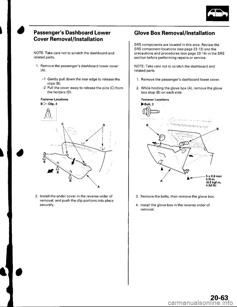
1. Remove the passenger's dashboard lower cover(A).
-1 Gently pull down the rear edge to release the
ctips (B).
-2 Pull the cover away to release the pins (C)from
the holders (D).
Fastener Locations
B >: Clip,3
AI jl
Install the under cover in the reverse order of
removal, and push the clip ponions into place
securety.
Glove Box Removal/lnstallation
SRS components are located in this area. Review the
SRS component locations (see page 23-13) and theprecautions and procedures (see page 23 14) in the SRS
section before performing repairs or service.
NOTE: Take care not to scratch the dashboard and
related pa rts.
1. Remove the passenger's dashboard lower cover.
2. While holding the glove box (A), remove the glove
box stop (B) on each side.
Fastener Localions
>Boh.2.-6\
{Ill fir-"b.-<,/
B
tJ
r-3t.oi,t-'
10.5 kgf m,4 tbf.ft)
4.
Remove the bolts, then remove the glove box.
lnstallthe glove box in the reverse order of
removal.
20-63
Page 720 of 1139
Dashboard
Dashboard Removal/lnstallation
SRS components are located in this area. Review the
SRS component locations (see page 23-13) and the
precautions and procedures (see page 23-14) in the SRS
section before performing repairs or service.
NOTE:. When prying with a flat-tip screwdriver, wrap it with
protective tape, and apply protective tape around the
related parts to prevent damage.. Have an assistant help you when removing and
installing the dashboa rd.. Take care not to scratch the dashboard, body, and
other related parts.
. Put on gloves to protect your hands.
1. Make sure you have the anti-theft code for the radio,
then write down the frequencies for the preset
buttons.
Disconnect the negative cable from the battery, and
wait at least three minutes before beginning work.
Remove these items:
. Driver's dashboard lower cover (see page 20-59). Driver's dashboard under cover (see page 20-60). Passenger's dashboard lower cover (see page
20-63). Glove box (see page 20-63). Consoles, front and rear (see page 20-57). Shift lever trim {see page 20-61). Center panel (see page 20-62). Kick panels, both sides (see page 20-50). A-pillar trim. both sides (see page 20-50). Steering column (see page 17-9)
20-66
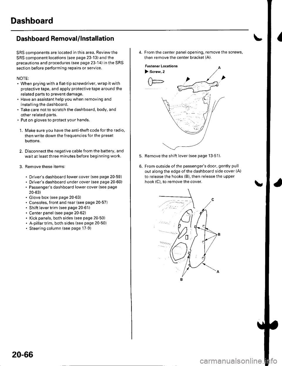
4. From the center panel opening, remove the screws,
then remove the center bracket (A).
Fastener Locations
):Screw,2
Remove the sh ift lever (see page 13-51).
From outside of the passenger's door, gently pull
out along the edge of the dashboard side cover (A)
to release the hooks (B), then release the upper
hook (C), to remove the cover.
Page 725 of 1139
Front Seat Removal/lnstallation
For some models: SRS components are located in this
area. Review the SRS component locations (see page
23-'13) and the precautions and procedures (see page
23-14) in the SRS section before performing repairs or
service.
NOTE. When prying with a flat-tip screwdriver, wrap it with
protective tape to prevent damage.. Take care not to scratch the body or tear the seat
covers.. Put on gloves to protect your hands.
1, Make sure you have the anti-theft code for the radio,
then write down the frequencies for the preset
butlons.
Disconnect the negative cable from the battery, and
wait at least 3 minutes before beginning work.
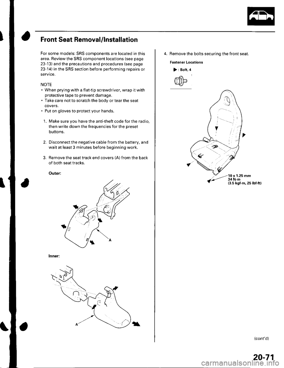
Remove the seat track end covers (A) from the back
of both seat tracks.
Outef:
lnner:
3.
\
4. Remove the bolts securing the front seat.
Fastener Locations
10 x 1.25 mm
> : Bolt,
@
(cont'd)
20-71
Page 727 of 1139
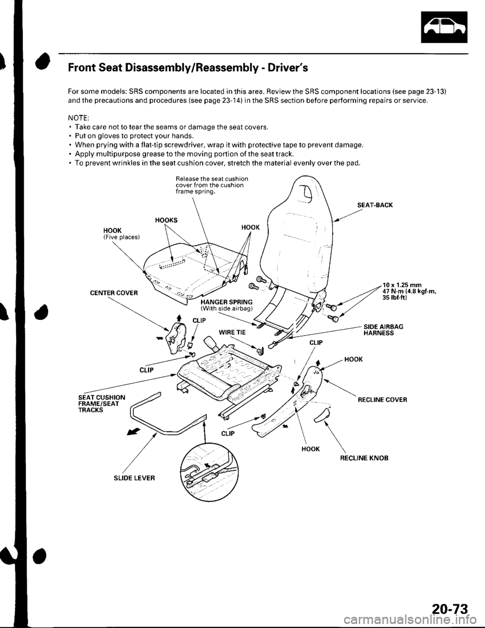
Front Seat Disassembly/Reassembly - Driver's
For some models: SRS components are located in this area. Review the SRS component locations (see page 23-13)
and the precautions and procedures (see page 23-14) in the SRS section before performing repairs or service.
NOTE:. Take care not to tear the seams or damage the seat covers,. Put on gloves to protect your hands.. When prying with a flat-tip screwdriver. wrap it with protective tape to prevent damage.' Apply multipurpose greasetothe moving portion of the seattrack.. To preventwrinkles in the seat cushion cover, stretch the material evenlyoverthe pad.
Release the seat cushioncover from the cushionframe spring.
SEAT-BACK
RECLINE COVER
RECLINE KNOB
10 x 'l.25 mm47 N.m {4.8 kgf.m,35 rbt.ft)
WIRE TIE
4
20-73
Page 728 of 1139
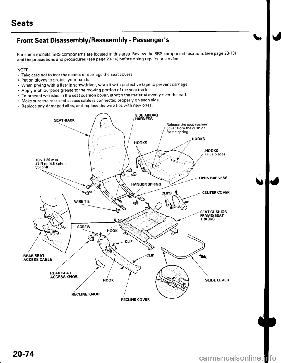
Seats
Front Seat Disassembly/Reassembly - Passenger's
For some models: SRS components are located in this area. Reviewthe SRS component locations (see page 23-'13)
and the precautions and procedures (see page 23-14) before doing repairs or service.
NOTE;. Take care not to tear the seams or damage the seat covers
. Put on gloves to protect your hands.
. When prying with a flat-tip screwdriver, wrap it with protective tape to prevent damage
. Apply multipu rpose grease to the moving portion of the seat track
. To Drevent wrinkles in the seat cushion cover, stretch the material evenly over the pad.
. lvlake sure the rear seat access cable is connected properly on each side
. Replace any damaged clips, and replace the wire ties with new ones
SIDE AIRBAGHARNESS
Release the seat cushioncover from the cushionframe spring.
10 x 1.25 mm47 N.m (4.8 kgf.m,3s rbf.ft)
SEAT"BACK
HANGER SPRING
OPDS HARNESS
CENTEB COVER
u
WIRE TIE
SEAT CUSHIONFRAME/SEATTRACKS
/REAR SEATACC€SS CABLE
N
*r(".o, /- IACCESSKNOB ,/ /
/HooK
SLIDE LEVER
,/CLIP
v/
20-74
RECLINE KNOB
RECLINE COVER