differential HONDA CIVIC 2002 7.G User Guide
[x] Cancel search | Manufacturer: HONDA, Model Year: 2002, Model line: CIVIC, Model: HONDA CIVIC 2002 7.GPages: 1139, PDF Size: 28.19 MB
Page 464 of 1139
M/T Differential
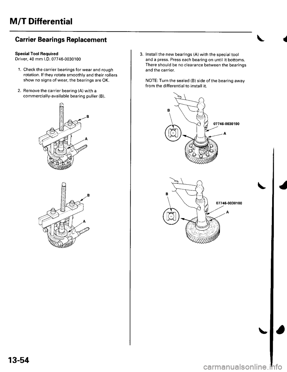
Carrier Bearings Replacement
Special Tool Bequired
Driver, 40 mm l.D. 07746-0030100
1. Check the carrier bearings for wear and rough
rotation. lf they rotate smoothly and their rollers
show no signs of wear, the bearings are OK,
2. Remove the carrier bearing (A) with a
commercially-available bearing puller (B).
13-54
\{
3. Install the new bearings (A)with the special tool
and a press. Press each bearing on until it bottoms.
There should be no clearance between the bearinos
and the carrier.
NOTE: Turn the sealed (B) side of the bearing away
from the differentialto install it.
077i16-0030100
07746-0030100
6
Page 465 of 1139
Oil Seal Replacement
Special Tools Required. Driver 07749-0010000. Oil seal driver attachment 07NAD-P20A100
1. Remove the differential assembly.
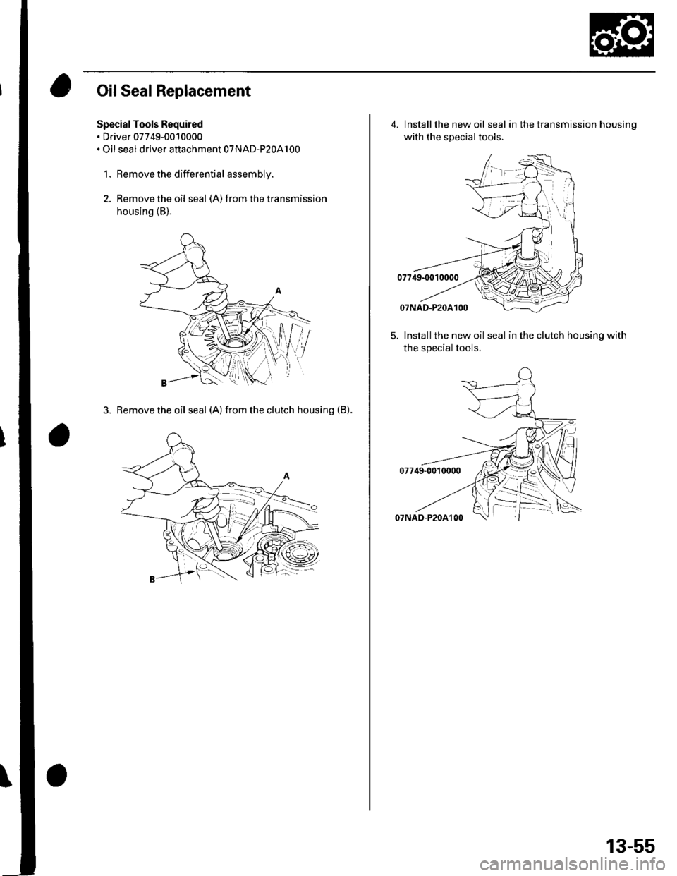
2. Remove the oil seal (A) from the transmission
housing (B).
3. Removetheoil seal (A) fromtheclutch housing (B).
4. Installthe new oil seal in the transmission housinq
with the special tools.
5. Installthe new oil seal in the clutch housing with
the special tools.
13-55
Page 466 of 1139
M/T Differential
Differential Thrust Clearance Adjustment
SpecialTool Required
Driver. 40 mm LD. 07746-0030100
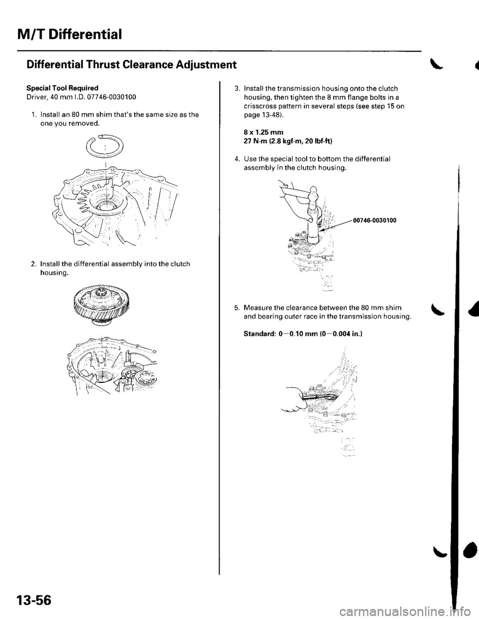
1. Install an 80 mm shim that's the same size as the
one you removeo.
2.Install the differential assembly into the clutch
housing.
13-56
5.
Install the transmission housing onto the clutch
housing, then tighten the 8 mm flange bolts in a
crisscross pattern in several steps (see step 15 on
page 13-48).
8 x 1.25 mm
27 N m (2.8 kgf'm, 20 lbf.ft)
Use the special toolto bottom the differential
assembly in the clutch housing.
00746-0030100
Measure the clearance between the 80 mm shim
and bearing outer race in the transmission housing.
Standard: 0 0.10 mm l0 0.004 in.)
-i.w.t ..1-- -- :,- -=.
Page 471 of 1139
Driveline/Axle
Driveshafts Removal (cont'd)
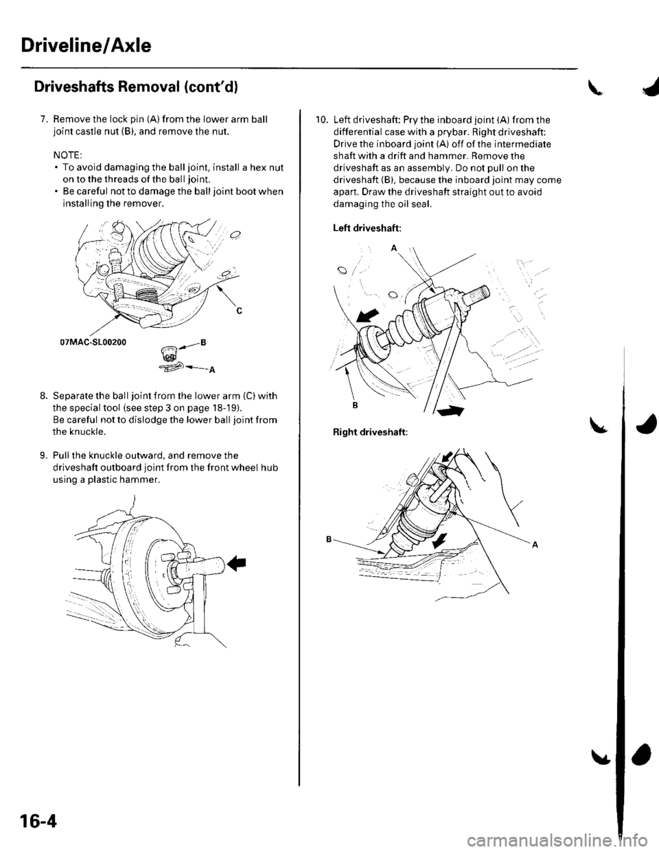
7. Remove the lock pin {A)from the lower arm balljoint castle nut (B), and remove the nut.
NOTE:. To avoid damaging the balljoint, install a hex nut
on to the threads of the ball joint,
. Be careful not to damage the balljoint boot when
installing the remover.
07MAC-S100200
w^'e
Separate the ball joint from the lower arm (C) with
the special tool (see step 3 on page 18-19).
Be careful not to dislodge the lower ball joint from
the knuckle.
Pull the knuckle outward, and remove the
driveshaft outboard joint from the front wheel hub
using a plastic hammer.
9.
.."8
16-4
\
10. Left driveshaft: Pry the inboard joint (A)from the
differential case with a prybar. Right driveshaft:
Drive the inboard joint (A) off of the intermediate
shaft with a drift and hammer. Remove the
driveshaft as an assembly. Do not pull on the
driveshaft (B), because the inboard joint may come
apart. Draw the driveshaft straight out to avoid
damaging the oil seal.
Left driveshaft:
a
t
Right driveshaft:
Page 485 of 1139
Driveline/Axle
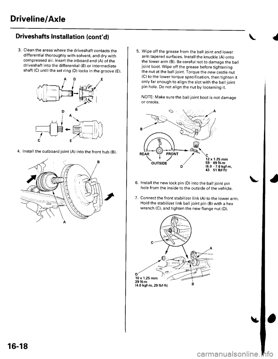
Driveshafts Installation (cont'd)
Clean the areas where the driveshaft contacts thedifferential thoroughly with solvent, and dry withcompressed air. Insenthe inboard end {A) ofthedriveshaft into the differential (B) or intermediateshaft {C) until the set ring (D) locks in the groove (E).
4. Install the outboard joint (A) into the front hub (B).
16-18
5. Wipe offthe grease from the ball ioint and lowerarm tapered surfaces. Installthe knuckle (A) ontothe lower arm {B). Be careful not to damage the balljoint boot. Wipe off the grease before tighteningthe nut at the ball joint. Torque the new castle nut(C) to the lower torque specification, then tighten itonly far enough to align the slot with the ball joint
pin hole. Do not align the nut by loosening it.
NOTE: Make sure the ball joint boot is not damageor cracks.
"-'t-
12 x 1.25 mm59 69 N.m(6.0 -7.0 kgf m,43 51 tbt.ftl
Installthe new lock pin {D) into the balljoint pin
hole from the inside to the outside of the vehicle.
Connect the front stabilizer link {A) to the lower arm.Hold the stabilizer link balljoint pin (B) with a hexwrench {C), and tighten the newflange nut {D).
7.
'10 x 1.25 mm39 N.m{4.0 kgf.m,29 lbf.ft)
{
Page 487 of 1139
Driveline/Axle
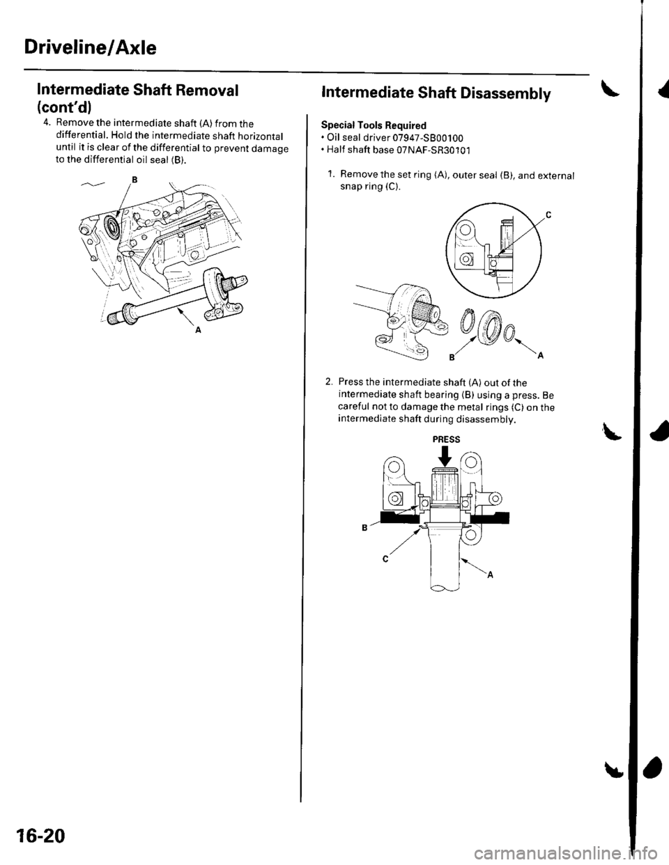
{Intermediate Shaft Removal
(cont'dl
4. Remove the intermediate shaft (A) from thedifferential. Hold the intermediate shaft horizontaluntil it is clear of the differential to prevent damageto the differential oil seal (B).
16-20
Intermediate Shaft Disassembly
Special Tools Required. Oil seal driver 07947-5800100. Half shaft base 07NAF-SR30101
1. Removetheset ring (A), outerseal (B), and externalsnap ring (C).
Press the intermediate shaft (A) out of theintermediate shaft bearing (B) using a press. Be
careful not to damage the metal rings (C) on theintermediate shaft during disassembly.
LPRESS
Page 491 of 1139
Driveline/Axle
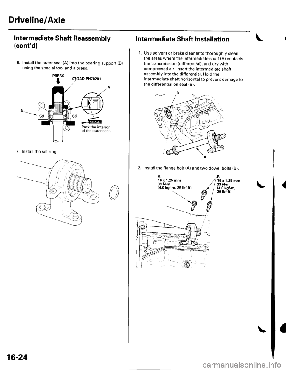
Intermediate Shaft Reassembly
(cont'd)
6. lnstallthe outer seal (A) intothebearingsupport(B)
using the special tool and a press.
7. Installthe set ring.
PRESS
I
Pack the interiorofthe outer seal.
16-24
Intermediate Shaft Installation
1. Use solvent or brake cleaner to thoroughly clean
the areas where the intermediate shaft {A) contacts
the transmission (differential), and dry with
compressed air. Insert the intermediate shaft
assembly into the differential. Hold the
intermediate shaft horizontal to prevent damage to
the differential oil seal (B).
2. Installthe llange bolt (A) and two dowel bolts (Bl.
A10 x 1.25 mm39Nm(4.0 kgf.m,29lbf.ft)
Bl0 x 1.25 mm39 N.m(4.0 kgf.m,29 tbf.ftl
(
Page 1134 of 1139
Service Manual Index
(cont'dl
Brake System Indicator CircuitCircuit DiagramConventional Brake Components..... 19-9TroubleshootingABS/TCS Components .... ....... ...... 19-55
Bulb, GeugeRep|acemenl................ .. ............2263
Bulb, HeadlightReplacement ......................................... 22-A1
Bumper, FrontRemoval/1nsra11ation ............................ 20 85
Bumper, RearRemoval/lnstallation... ... . .....20.86
Combination Light SwilchTesVReplacement ..............................22 80
Connecting Rod BearingsRep|acement...................... .......-....7-8
Connecting Rod Boltsf nspection ....................-.-.-.-.................... 7 -24
Connecting RodsInspection ........,,.,.,...,.,.,.,.,,,,.,,,.,.,.,.,.,.,.,.. 7 5
Connectors(See first page of this Index)
Conventional Brake Component3Component Location Index ................... 19'3Troub1eshootin9 ..................................... 19-4
Cylinder Head AssemblyComponent Location Index ..................... 6-3Inspection ................................................. 6 6Removal ..........&�23Insta11alion .............................................. 6 39
Cylinder Head Cover8emova1 ..............-.-................................. 6-22Installation ..............................................6-41
Cylinder Head, BareInspecton..,.....,.
D
c
Cable ReelReplacement....................................... 23-1 19
CamshaftInspection .......................-...-................... 6-29
Cargo Area LightTesVRep1acement ................................ 22-97
CarpetReplacement.....-...-..... ... ......-.20-55
Ceiling Light-estrReplacement ................................ 22.96
Charging SystemComponent Location Index................... 4-20Circuit Diagram ...................................... 4-21
19-8
CoolantInspection .................. ..... .. 106Replacement................. ... . .. 10 6
Coolant Temperature Gat|geTroub1eshootin9................................... 22 64
Cooling SyslemComponent Location Index................... 10-2
Countershaft BearingsReplacement............... ..................... 13-42
Cowl CoverReplacement............... .. ..... ....20-95
CrankshaftRemoval .................................................. 7 -12
Repair ..................
Inspec(on,,,,,........1 14
Dampers. FrontReplacement................ ..................... 18 20
Oampers, RearRep1acement......................................... 18-34
Dash VentsBemoval/lnstallation .-.......................... 20-64
DashboardBemoval/1nsta11ation ............................ 20-66
Oashboard Center PanelRemoval/1nstaf 1ation ............................ 20 62
Dashboard Lower CoverRemoval/lnstallation ...................... 20-59, 63
Dashboard Under CoverRemoval/lnstallation ............................ 20 60
Diff erential Carrier Bearings, M/TRep1acement,,......,...,...,.,.,,,.,.,,,........,.,. 13-54
Ditferential Oil Seals, M/T8ep1acement......................................... 13-55
Differential Pinion Gears, M/TInspection .,....-,.,,,.,..,.-,.,.........,.,.,,, 13 53
OLC CircuitTroubleshooting ................................ 1 1-109
Door GlassRep1acement.,.,,,,,,,,,,,.,,,,,,,,,,.,.,.,.,.,,,,,,.,, 20-9Adjustment. .. .....................20-11
Door Glass WeathelstripsReplacement .............-.. . . . ..........-......20 10
Door LatchesReplacement ..........-.-.............................. 20-7
Door Lock ActuatorsTest ...................................................... 22-154
Door Lock Knob SwitchesTest -......... . . . - . . . . . . . . ......22-160
Door Lock SwitchesTest ........... ............................ ............. 22-160
Door Outer HandlesRep1acemen1 ........................................... 20-6
3
Child Seat Tether AnchorRemoval/lnstaf lat;on .. ........................ 23 11
CKP (Crankshaft Position) SonsorReplacement....................................... 1 1-116
ClutchComponentLocation 1ndex................... 12-3Rep1acemen1........................................... 12-9
Clutch InteYlock SwitchTest.....-........-...-............. ...---.-.......4-6
Clutch Master CylinderReplacement........................................... 12 5
clutch PedalAdjustment ............................................. 12 4
Clutch Pedal Position SwitchTest.,.,,,,,.,,,.,.,,,,,,.,.,,,,,,,,,.,,,,,.. ......445
lnstallation.................. . ..... .....1-24
Crankshalt Main BearingsReplacement........-.-.................................. 7-6
CrankshaftOil Seal,Transmission End1nstanation .............................................. 7 28
Crankshafl PulleyRemoval/lnstallation -..................-.......... 6-1 1
Cruise Control Actuator
Troubleshooting
Clutch Slave CylindorBeplacemeit...
...................... 4-43
.......4-22
Test
12-1
RepIacement........................................... 4-44
Cruise Control Actuator CableAdjustment ............................................. 4 45
Cruise Control Main SwitchTesVRep1acement .................................. 4 42
Cruise Control Set/Resume/Cancel SwitchTesVRep1acement .................................. 4 42
Cruise Control SystomComponent Localion Inde\................... 4-36Circuit Diagram ....-................................. 4 37
Cruise Control UnitInputTest.............................. .. ...4,40CMP {Camshaft Positionl Senso]Replacement....-...-.............................. 1 1-128
CMP (TDC) SensorsReplacement............-.......................... 1 1 1 14
Page 1137 of 1139
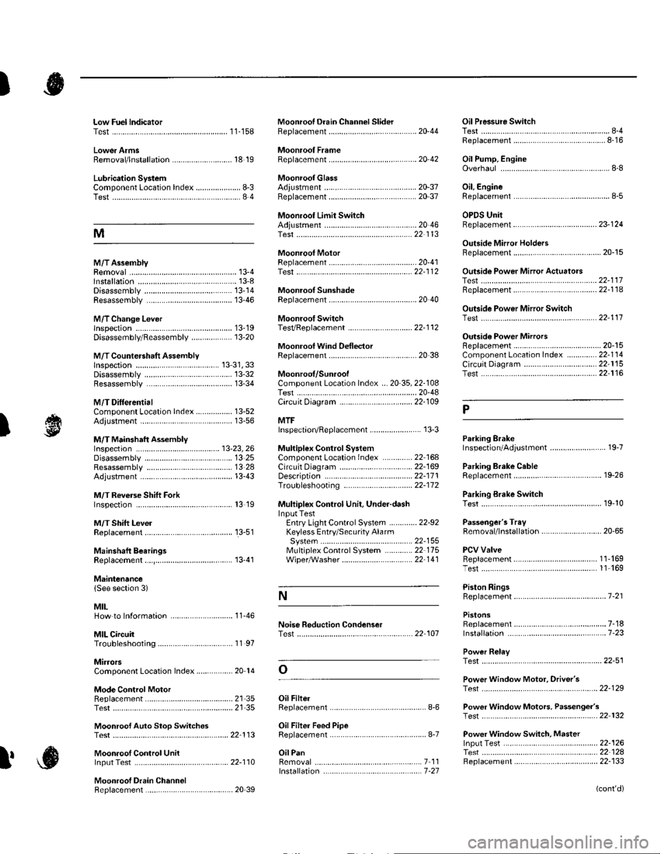
)
Low Fuel lndicatorTest.....................11-158Moonroof Drain Channel SliderReplacement......................................... 20'44
Moonroof FrameRep1acement,,,,,,,,,,.,.,.,.,.,.,.,,,,,,............ 20 42
MoonroolGlassAdiustment ........................................... 20-37Rep1acement......................................... 20 37
Moonroot Limit SwitchAdjustment ........................................-.- 20 46Test ...................................................... 22 113
Moonrool MotorReplacement....-.................................... 2D-41
Oil Pressure SwitchTest ................-.-........-................................ 8-4Replacement.........-................................. 8-16
Oil Pump, EngineOverhau1 ................................................... 8-8
Oil, EngineReplacement...-................-.-...................... 8-5
OPDS UnitReplacement....................................... 23- 124
Outside Mirror HoldersBeplacement......................................... 20-15
Outside Power Mirror ActuatorsTest ...................................................... 22-117Bepf acement..-.................................... 22-1 14
Outside Power Mirror SwitchTest ..-................................................... 22-111
Outsid€ Power MirrorsReplacement............................ ... .. . . . 20-15Component Location lndex .............. 22- 114Circuit Diagram .................................. 22-115Test -..................................................... 22-116
Lower ArmsRemoval/1nsta11ation............................ 18 19
Lubrication SystemComponent Location Index..................... 8-3Test............................................................ 8 4
M
M/TAssemblyRemoval.......... 13-4 Test...................... 22-1 12lnstallation............. 13-8
.........21,35
Disassembly ......................................... 13-14Resassembly .. ... ................. 13-46
M/TChange Leverlnspection ............................................. 13-19Disassembly 8eassemb1y ................... 13-20
M/T Countershaft AssemblyInspection ....................................... 13 31, 33Disassemb1y ......................................... 13-32Resassemb|y ........................................ 13-34
M/T DifferentialComponentLocation Index................. 13-52Adiuslment ........................................... 13-56
M/T Maifthaft Assembly1nspection ... ................................... 13-23, 26Disassembly ......................................... 13 25Resassembly ........................................ 13 28Adjustment ........................................... 13-43
M/T Reverse Shift ForkInspection .................... ........................ l3 19
M/T Shift LevelReplacement......................................... 13-51
Mainshaft BearingsReplacement....,.................................... 13 41
MairtenancelSee section 3)
MILHow to Informatron ............................. 1 1.46
MIL CircuitTroubleshooting .......... .- . . . . ......... 11 97
MirrorsComponentLocation Index................. 20'14
Mode Control MotorReplacement
Moonrool SunshadeRep1acement....................... . . ............. 20 40
Moonroof SwitchTesVRep1acement .............................. 22- l 12
Mooniool Wind Def lectorReplacement.......................-................. 20-38
Moonroof/SunroofComponent Location Index ... 20-35, 22-108Test ........................................................ 20-48Cf rcuit Diagram .................................. 22- 109
MTFInspection/Rep1acement. .......... ........... 13-3
Muhiplex Control SystemComponentLocation lndex ..............22 168Circuit Diagram .................................. 22-1690escription ......................................... 22-17 1Troubleshooting ................................ 22-17 2
Muliiplex Control Unit, Under-dashInput TestEntry Light Control Sysiem ............. 22-92Keyless Entry/Security AlarmSystern .-....................................... 22-155MultiplexControl System .............22 115Wiper/Washer................................. 22'1 41
NoiseTest,,Reduction Condenser
Parking ErakeInspection Adjustment ........... .............. 19-7
Parking Brake CableRep1acement......................................... 19-26
Parking Erake Switch
P
l
Test ...................... 19-10
Test............................... . ...........2135
Moonroof Auto Stop SwitchosTest ...................................................... 22'113
Moon.oot Control Unillnput Test ............................................ 22-110
Moonroof Drein ChannelBeplacement ... . ....... ......................... 20 39
Oil Filte]Replacement............................................. 8-6
Oil Filter Feed PipeReplacement............... . ..-,...,.,,,,,,,,8-7
Oil PanRemoval .............,.,,,,,,,,,,,,.,.,,,.........-....... 7 1 1lnstallation .............................................. 7 -27
Passenger's TraVRemoval/lnstallation ............................ 20-65
PCV ValveBeplacement....................................... 1 1'169Test........................................... l1 169
Piston Rings8ep1acement................................-.-...-.- 7-21
PistonsReplacement...................-....................... 7-181nsta|1ation ...................................... ...1-23
Power R€layTest ...............-.-...................................... 22-51
Power Window Motor, Driver'stesl.....,,,, .,.,,,............
Power Window Motors, Passenger's
Power Window Switch, Masterlnput Test ..........-.........-....................... 22-126Tesr ....... . ............................................ 22 124Replacement....................................... 22-133
N
..............22 101
o
l' ,e
(cont'd)