light HONDA CIVIC 2002 7.G User Guide
[x] Cancel search | Manufacturer: HONDA, Model Year: 2002, Model line: CIVIC, Model: HONDA CIVIC 2002 7.GPages: 1139, PDF Size: 28.19 MB
Page 105 of 1139
Gylinder Head
IValve Clearance Adjustment (cont'd)
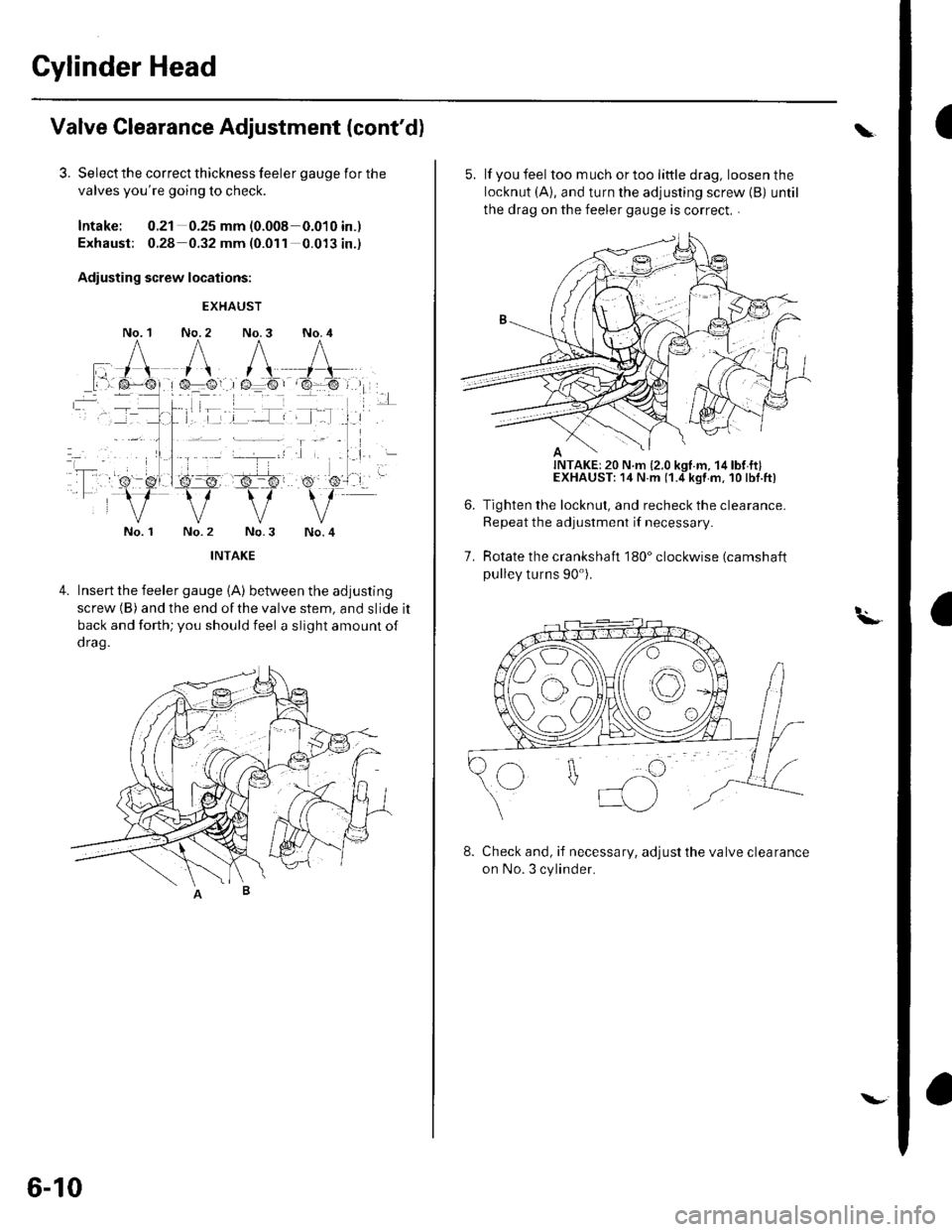
3. Select the correct thickness feeler gauge for the
valves you're going to check.
Intake: 0.21 0.25 mm (0.008-0.010 in.)
Exhaust; 0.28 0.32 mm (0.011 0.013 in.)
Adiusting screw locations:
No. 1
EXHAUST
No. 2 No.3 No. 4
No. 1No.4
4.Insert the feeler gauge {A) between the adjusting
screw (B) and the end ofthe valve stem, and slide it
back and forth; you should feel a slight amount of
d rag.
6-10
\.
5. lf you feel toomuchortoolittledrag, loosenthe
locknut (A), and turn the adjusting screw {B) until
the drag on the feeler gauge is correct. .
Tighten the locknut, and recheck the clearance.
Repeat the adjustment if necessary
Rotate the crankshaft 180" clockwise (camshaft
pulley turns 90').
7.
t.\-
8. Check and, if necessary, adjust the valve clearance
on No. 3 cylinder.
Page 126 of 1139
Valves, Springs, and Valve Seals Removal
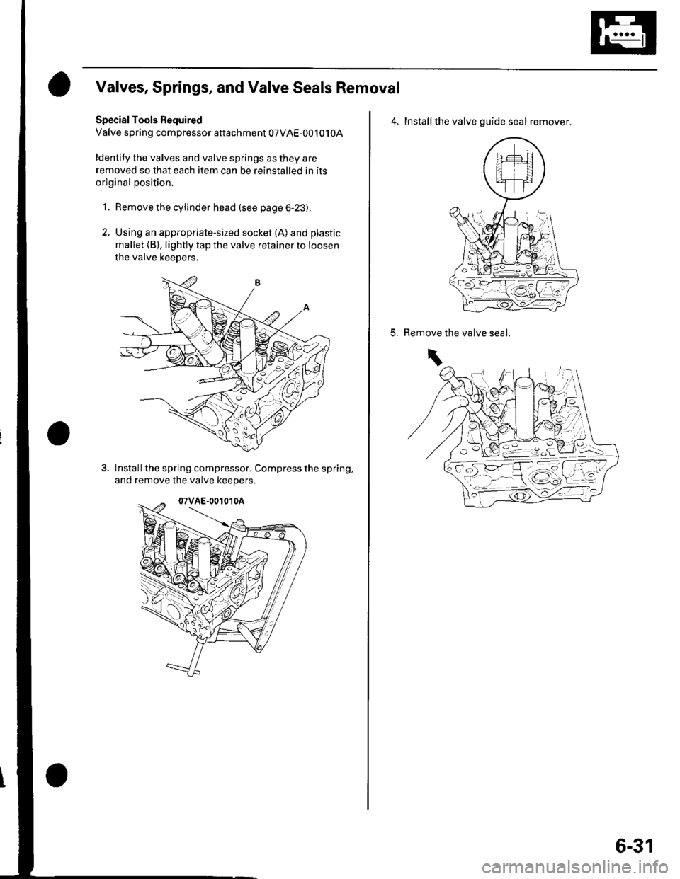
Special Tools Bequired
Valve spring compressor attachment 07VAE-001010A
ldentify the valves and valve springs as they are
removed so that each item can be reinstalled in its
original position.
1. Remove the cylinder head (see page 6-23).
2. Using an appropriate-sized socket (A) and plastic
mallet {B), lightly tap the valve retainer to loosen
the valve keepers.
Install the spring compressor. Compress the spring,
and remove lhe valve keepers.
4. Installthe valve guide seal remover.
5.the valve seal.Remove
\
6-31
Page 130 of 1139
Valve Seat Reconditioning
1. Inspect valve stem-to-guide clearance (see page 6-
32). lf the valve guides are worn, replace them (see
page 6-33) before cutting the valve seats.
2. Renew the valve seats in the cylinder head using a
valve seat cutter.
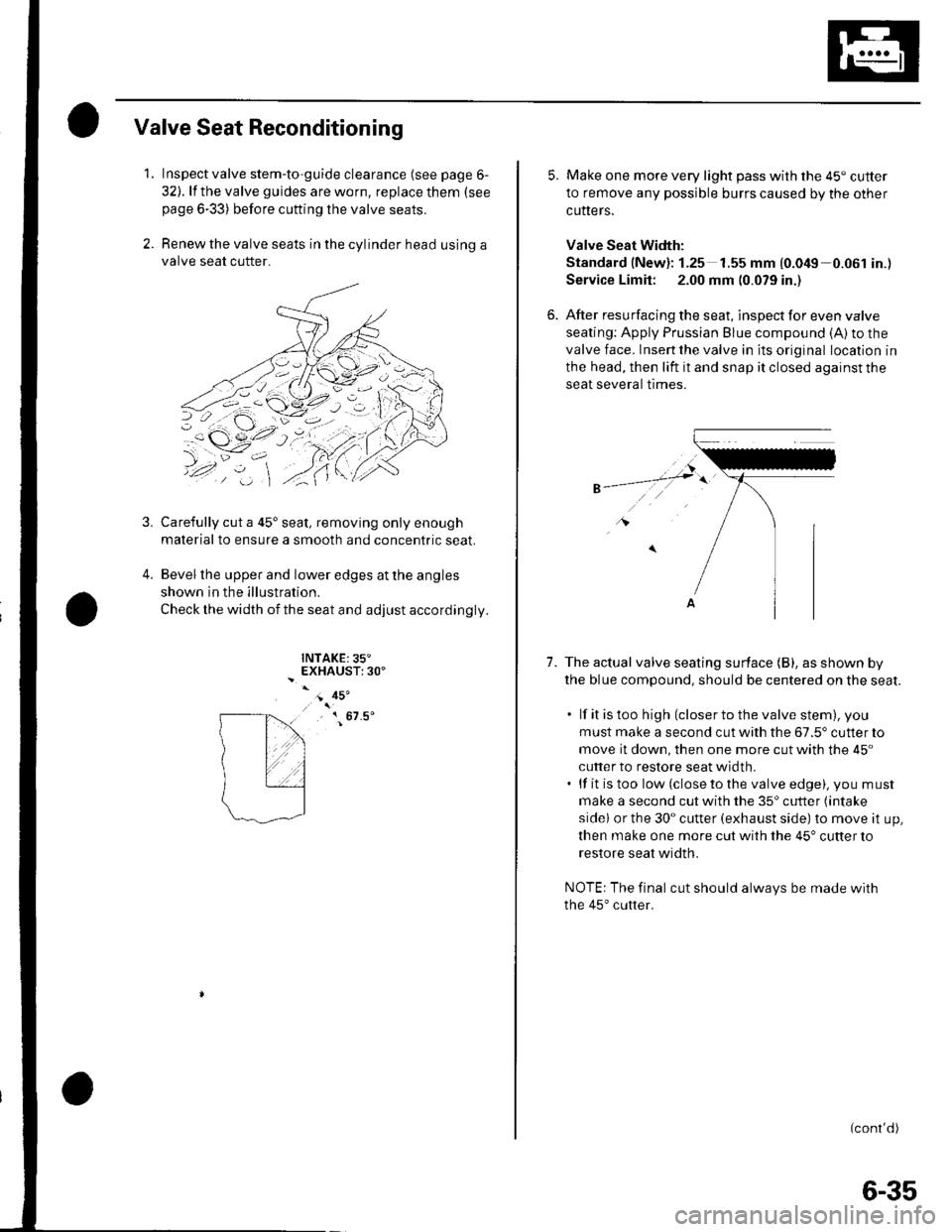
Carefully cut a 45'seat, removing only enough
material to ensure a smooth and concentric seat.
Bevel the upper and lower edges at the angles
shown in the illustration.
Check the width of the seat and adjust accordingly.
INTAKE:35"EXHAUST:30'
3,
4.
- 45'
, { 67.5'
5. Make one more very light pass with the 45" cutter
to remove any possible burrs caused by the other
cutters.
Valve Seat Width:
Standard (New): 1.25 1.55 mm {0.049 0.061 in.)
Service Limit: 2.00 mm (0.079 in.)
6. After resurfacing the seat, inspect for even valve
seating: Apply Prussian Blue compound (A) to the
valve face. Insert the valve in its original location in
the head, then lift it and snap it closed against the
seat several trmes.
1.The actual valve seating surface (B), as shown by
the blue compound, should be centered on the seat.
. lf it is too high (closer to the valve stem), you
must make a second cut with the 67.5' cutter to
move it down, then one more cut with the 45"
cutter to restore seat width.. lf it is too low (close to the valve edge), you must
make a second cut with the 35'cutter (intake
sidel or the 30" cutter (exhaust side) to move it up,
then make one more cut with the 45" cutter to
restore seat width.
NOTE: The final cut should always be made with
the 45'cutter.
(cont'd)
6-35
Page 132 of 1139
Valves, Springs, and Valve Seals Installation
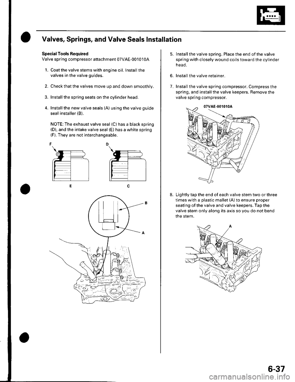
Special Tools Required
Valve spring compressor attachment 07VAE-00101 0A
1. Coat the valve stems with engine oil. lnstall the
valves in the valve guides.
2. Check that the valves move up and down smoothly.
Installthe spring seats on the cylinder head.
Install the new valve seals (A) using the valve guide
seal installer (B).
NOTE: The exhaust valve seal (C) has a black spring(D), and the intake valve seal (E) has a white spring(F). They are not interchangeable.
6.
lnstallthe valve spring. Place the end ofthe valve
spring with closely wound coils toward the cylinder
n eao.
Install the valve retainer.
Installthe valve spring compressor, Compress the
spring, and install the valve keepers. Remove the
valve spring compressor.
Lightly tap the end of each valve stem two or three
times with a plastic mallet (A) to ensure proper
seating of the valve and valve keepers. Tap the
valve stem only along its axis so you do not bend
the stem.
7.
6-37
Page 137 of 1139

Gylinder Head
Cylinder Head Gover Installation (cont'd)
Set the spark plug seals (A) on the spark plug tubes.
Once the cylinder head cover (B) is on the cylinderhead, slide the cover slightly back and forth to seat
the head cover gasket.
Inspect the cover washers (C). Replace any washer
that is damaged or deteriorated.
6-42
7. Tighten the bolts in two or three steps. In the final
step, tighten all bolts, in sequence, to 9.8 N.m (1.0
kgf.m, 7.2 lbf.ft).
8. Install the dipstick (A) and breather hose iB).
\
\l'
Page 155 of 1139
Cylinder Honing
Only a scored or scratched cylinder bore should be
noneo.
Measure the cylinder bores {see page 7-15).
lf the block is to be reused, hone the cylinders and
remeasure the bores.
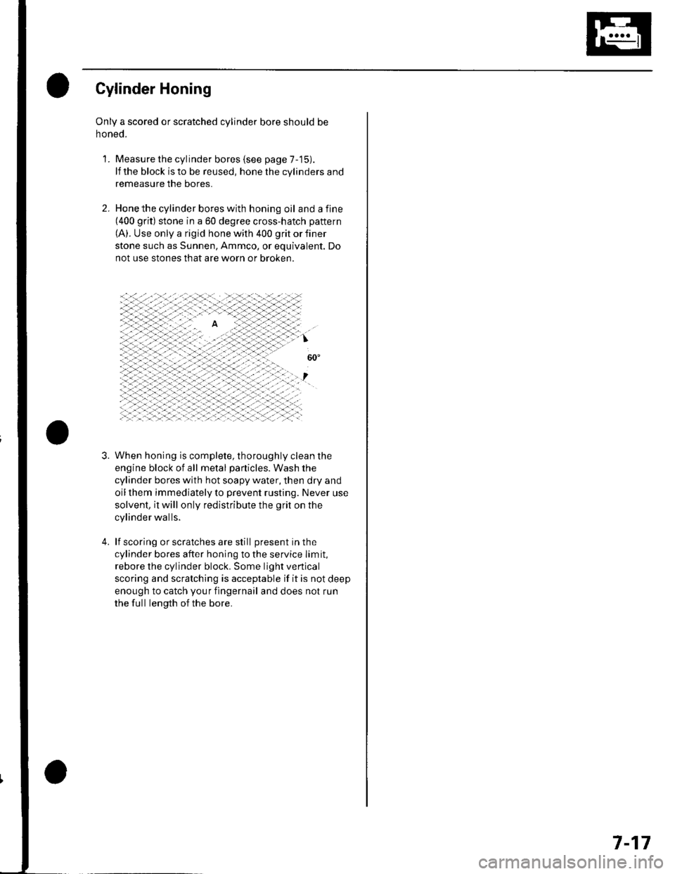
Hone the cylinder bores with honing oil and a fine(400 grit) stone in a 60 degree cross-hatch pattern
(A). Use only a rigid hone with 400 grit or finer
stone such as Sunnen, Ammco, or equivalent. Do
not use stones that are worn or broken.
When honing is complete, thoroughly clean the
engine block of all metal particles. Wash the
cylinder bores with hot soapy water, then dry and
oil them immediately to prevent rusting. Never use
solvent, it will only redistribute the grit on the
cylinder walls.
lf scoring or scratches are still present in the
cylinder bores after honing to the service limit,
rebore the cylinder block. Some light vertical
scoring and scratching is acceptable if it is not deep
enough to catch your fingernail and does not run
the full length of the bore.
'L
3.
7-17
Page 172 of 1139
Engine Lubrication
Engine Oil Filter Replacement
Special Tool Fequired
Oil filter wrench 07HAA-PJ70100
Engine Oil Filter (3/4-turn type)
1. Remove the oil filterwiththesDecial tool.
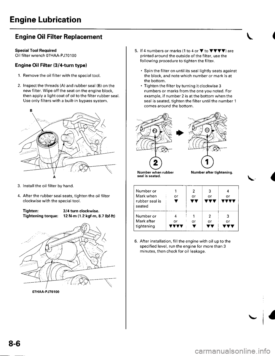
2. Inspect the threads {A) and rubber seal (B) on the
new filter. Wipe off the seat on the engine block,
then apply a light coat of oil to the filter rubber seal.
Use only filters with a built-in bypass system.
Installthe oilfilter by hand.
After the rubber seal seats, tighten the oil filter
clockwise with the special tool.
Tighten: 3/4 turn clockwise.
Tightening torque: 12 N.m (r.2 kgf.m,8.7 lbf.ft)
07HAA-PJ70100
8-6
\,
5. lf 4 numbers or marks (1 to 4 or V to VVVV) are
printed around the outside of the filter, use the
following procedure to tighten the filter.
. Spin the filter on until its seal lightly seats against
the block, and note which number or mark is at
the bottom.. Tighten the filter by turning it clockwise 3
numbers or marks from the one you noted. For
example, if number 2 is at the bottom when the
seal is seated, tighten the filter until the number 1
comes around the bottom.
Number when rubberseal is seated.Number after tightening.
(\..
6. After installation, fill the enginewith oil uptothe
specified level, run the engine for more than 3
minutes, then check for oil leakage.
Number or
Mark when
rubber seal is
1
or
V
2
or
VV
3
or
VVV
4
or
VVVV
Number or
Mark after
tightening
41
or or
vvvv. v
2
or
VV
3
or
VVV
Page 213 of 1139
Fuel and Emissions Systems
General Troubleshooting Information (cont'd)
ECM Updating and Substitution for Testing
Special Tools Bequired
Honda Interface Module (HlM) EOS05435570
Use this procedure when you have to substitute a
known-good ECM in a troubleshooting procedure.
U pdate the ECM only if the ECN4 does not already have
the latest software loaded,
NOTE;. lMake sure the battery is fully charged before you
update the ECN4.. To prevent ECM damage during the update, do not
turn the ignition switch OFF, and do not use any of
the vehicle's electrical devices (light, horn, radio, etc. ).
How to Update the ECM
1. Turn the ignition switch ON (ll). Do not startthe
eng Ine.
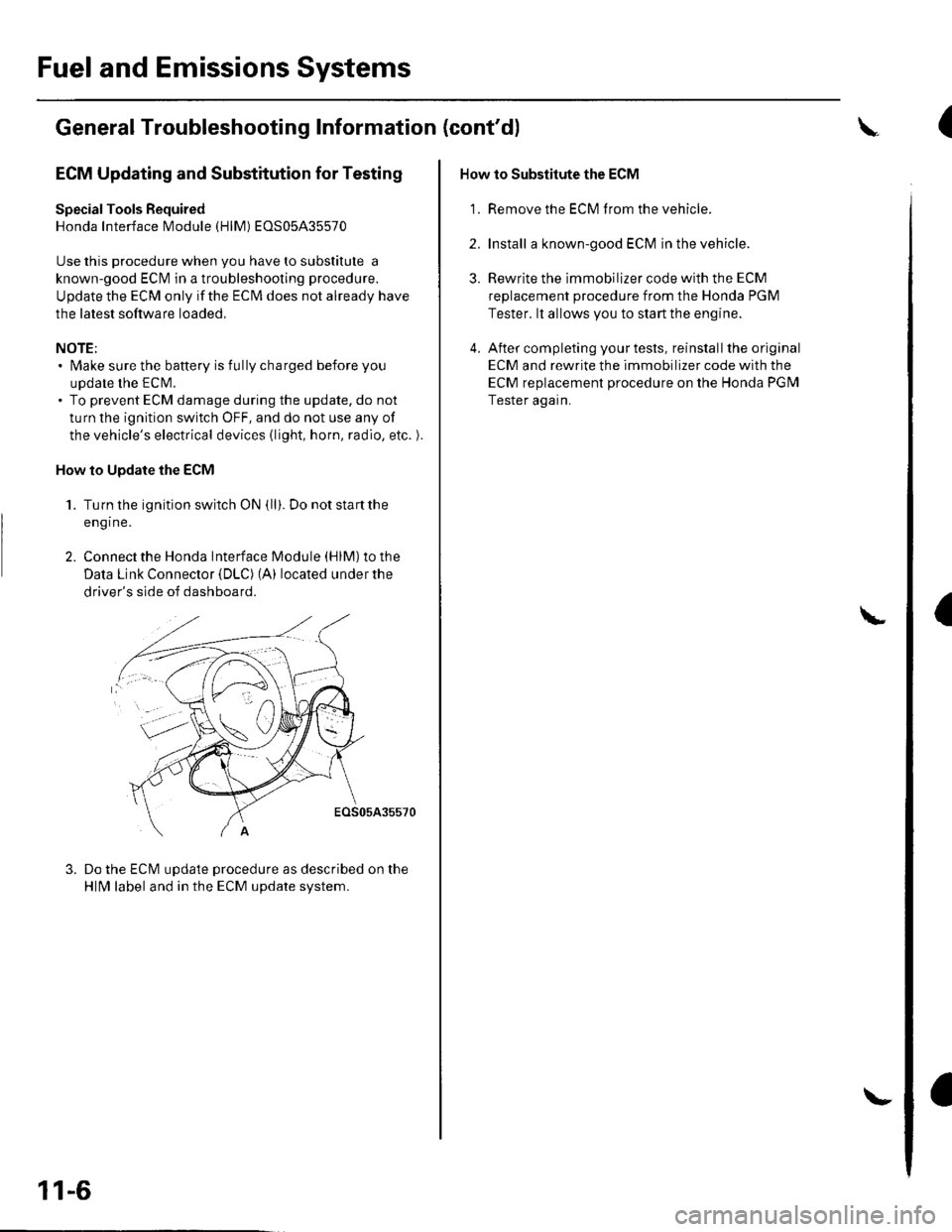
2. Connect the Honda lnterface Module (HlM) to the
Data Link Connector {DLC) (A) located under the
driver's side of dashboard.
EOS05A35570
Do the ECM update procedure as described on the
HlN4 label and in the ECM update system.
11-6
\-
How to Substitute the ECM
'1. Remove the ECM f rom the vehicle.
2. Install a known-good ECM in the vehicle.
3. Rewrite the immobilizer code with the ECM
replacement procedure from the Honda PGM
Tester. lt allows you to start the engine.
4. After completing your tests, reinstall the original
ECM and rewrite the immobilizer code with the
ECM replacement procedure on the Honda PGM
Tester again.
L
(
I
Page 236 of 1139
wEc/wc
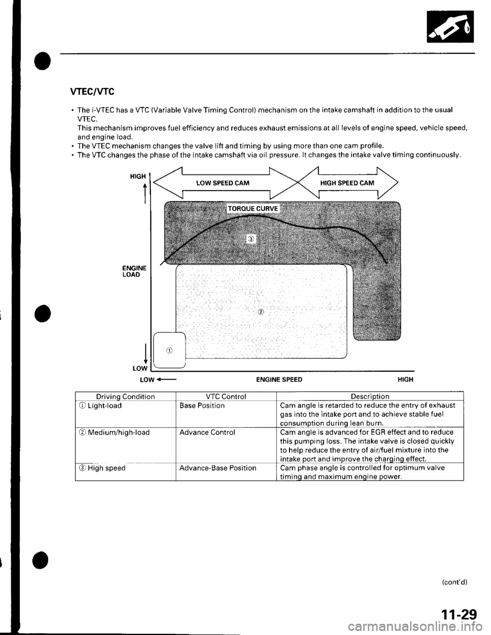
The i-WEC has a VTC (Variable Valve Timing Control) mechanism on the intake camshaft in addition to the usual
VTEC.
This mechanism improves fuel efficiency and reduces exhaust emissions at all Ievels of engine speed, vehicle speed.
and engine load.
The VTEC mechanism changes the valve lift and timing by using more than one cam profile.
The VTC changes the phase of the intake camshaft via oil pressure. lt changes the intake valve timing continuously.
HIGH
i
LOW <-ENGINE SPEED
Drivino ConditionVTC ControlDescriDtion
Qr Light-loadBase PositionCam angle is retarded to reduce the entry of exhaust
gas into the intake port and to achieve stable fuel
consumDtion durinq lean bu rn.
?l M ed iu m/h ig h-loadAdvance ControlCam angle is advanced for EGR effect and to reduce
this pumping loss. The intake valve is closed quickly
to help reduce the entry of airlfuel mixture into the
intake port and improve the charging effect.
€) High speedAdvance-Base PositionCam phase angle is controlled for optimum valve
timinq and maximum enoine oower.
{cont'd)
11-29
Page 299 of 1139
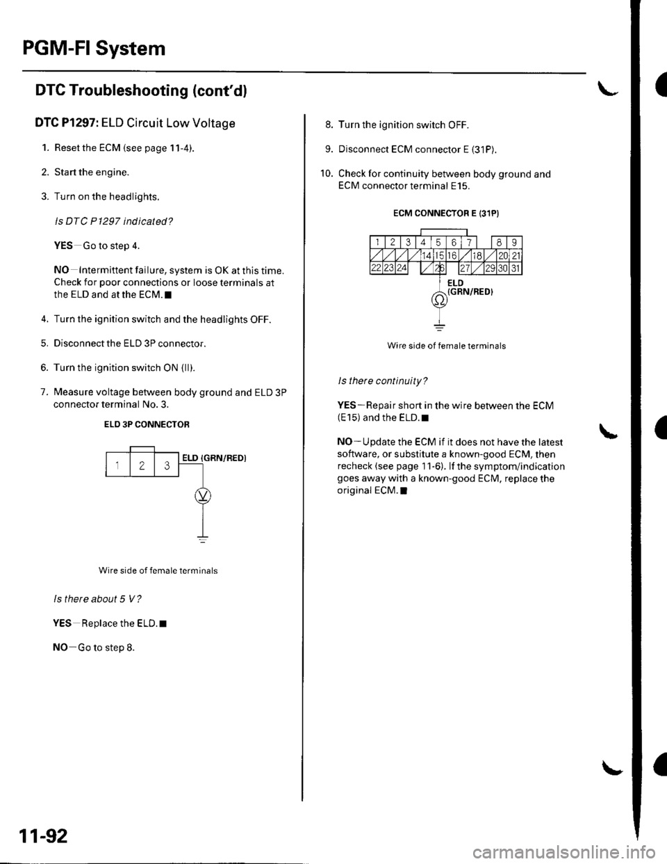
PGM-FI System
I
a
DTC Troubleshooting (cont'dl
DTC Pl297: ELD Circuit Low Voltage
1. Reset the ECM {see page 11-4).
2. Start the engine.
3. Turn on the headlights.
ls DTC P1297 indicated?
YES Go to step 4.
NO Intermittent failure, system is OK at this time.
Check for poor connections or loose terminals at
the ELD and at the ECM.I
4. Turn the ignition switch and the headlights OFF.
5. Disconnectthe ELD 3P connector.
6. Turn the ignition switch ON {ll).
7. Measure voltage between body ground and ELD 3P
connector terminal No. 3.
ELO 3P CONNECTOB
{GRN/REDI
Wire side of female terminals
ls there about 5 V?
YES Replace the ELD. t
NO-Go to step 8.
Z3ELD
11-92
8. Turn the ignition switch OFF.
9. Disconnect ECM connector E {31P).
10. Check for continuity between body ground and
ECM connector terminal E15.
ECM CONNECTOR E 131PI
I l2l3456178I
totd/ 12021,2 2al2/tA31
ELD(GRN/RED}7\'
Wire side of female terminals
ls there continuity?
YES-Repair short in the wire between the ECM(E 15) and the ELD. r
NO- U pdate the ECM if it does not have the latest
software, or substitute a known-good ECM, then
recheck (see page 1 1-6). lf the symptom/indication
goes away with a known-good ECM, replace the
original ECM.I