stabili HONDA CIVIC 2002 7.G User Guide
[x] Cancel search | Manufacturer: HONDA, Model Year: 2002, Model line: CIVIC, Model: HONDA CIVIC 2002 7.GPages: 1139, PDF Size: 28.19 MB
Page 562 of 1139
Front and Rear Suspension
WheelAlignment
The suspension can be adjusted for front camber, front
toe, and rear toe. However, each of these adjustments
are interrelated to each other. For example, when you
adjust the toe, the camber changes. Therefore, you
must adjust the front wheel alignment whenever you
adjust the camber or toe.
Pre-Alignment Checks
For proper inspection and adjustment of the wheel
alignment, do these checks:
1. Release the parking brake to avoid an incorrect
measurement.
Make sure the suspension is not modified.
Check the tire size and tire pressure
Tire size:
Front/rear: 195/60R15
Tire pressure:
Front: 230 kPa {2.3 kgf/cm',33 psil
Rear: 210 kPa |'2.1 kgf/cm', 30 psi)
Check the runout of the wheels and tires.
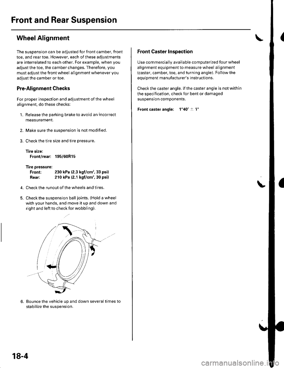
Check the suspension ball joints. (Hold a wheel
with your hands, and move it up and down and
right and left to check for wobbling),
2.
3.
Bounce the vehicle up and down several times to
stabilize the suspension.
18-4
Front Caster lnspection
Use commerciallv available comDuterized four wheel
alignment equipment to measure wheel alignment
(caster, camber, toe, and turning angle). Follow the
eouioment manufacturer's instructions.
Check the caster angle. lf the caster angle is not within
the specification, check for bent or damaged
susoensron comoonents.
Front caster angle: 1'40't 1"
\
Page 563 of 1139
Front Camber Inspection
Use commercially available computerized four wheel
alignment equipment to measure wheel alignment(caster, camber, toe, and turning angle). Follow the
equipment manufacturer's instructions.
Check the camber angle. lf the camber angle is not
within the specification, adjust the camber.
Front camber angle: 0"30' t 45'
Front Camber Adjustment
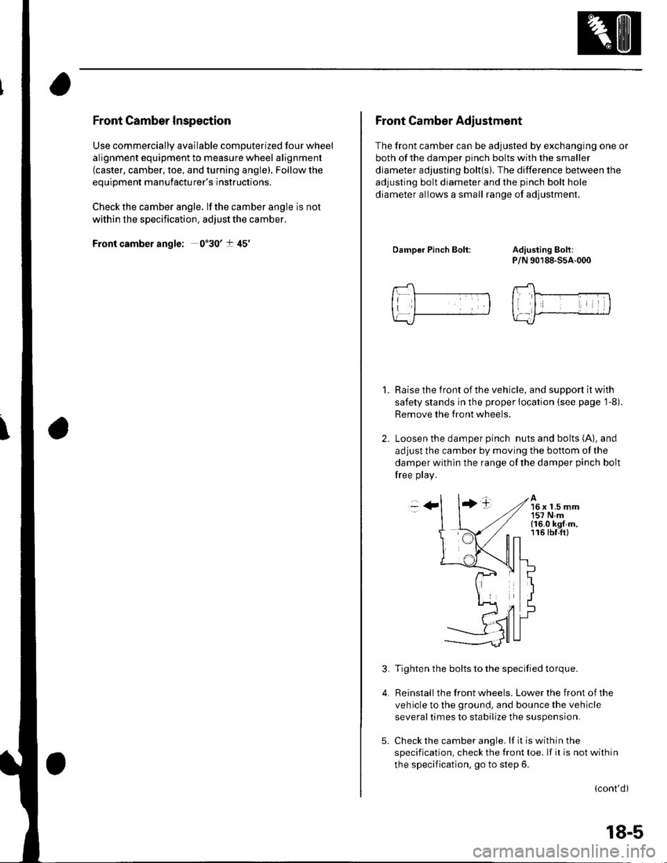
The front camber can be adjusted by exchanging one or
both of the damDer Dinch bolts with the smaller
diameter adjusting bolt(s). The difference between the
adjusting bolt diameter and the pinch bolt hole
diameter allows a small range of adjustment.
DamDer Pinch Bolt:Adiusting Boh:
P/N 90188-55A-000
Raise the front of the vehicle, and support it with
safety stands in the proper location (see page 1-8).
Remove the front wheels.
Loosen the damper pinch nuts and bolts (A), and
adjust the camber by moving the bottom of the
damper within the range of the damper pinch bolt
free play.
1.
-++tA16 x 1.5 mm157 N.m(16.0 kgf.m,116 tbf.ftl
3.
4.
Tighten the bolts to the specified torque.
Reinstall the front wheels. Lower the front of the
veh icle to the ground, and bounce the vehicle
several times to stabilize the suspension.
Check the camber angle. lf it is within the
specification, check the front toe. lf it is not within
the specification, go to step 6.
(cont'dl
5.
18-5
Page 564 of 1139
Front and Rear Suspension
Wheel Alignment (cont'd)
7.
Raise the front of the vehicle, and support it with
safety stands in the proper location (see page 1-8).
Remove the front wheels.
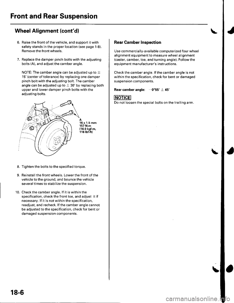
Replace the damper pinch bolts with the adjusting
bolts (A), and adjust the camber angle.
NOTE: The camber angle can be adjusted up to t
15' (center of tolerance) by replacing one damper
pinch bolt with the adjusting bolt. The camber
angle can be adjusted up to a 30' by replacing both
upper and lower damper pinch bolts with the
adjusting bolts.
15 x 1.5 mm157 N.m{16.0 kgt.m,116 tbf.ft)
8.Tighten the bolts to the specified torque.
Reinstall the front wheels. Lower the front of the
vehicle to the ground, and bounce the vehicle
several times to stabilize the suspension.
Check the camber angle. lf it is within the
specification, check the front toe. and adjust it if
necessary. lf it is not within the specification,
readjust, and recheck. lJ the camber angle cannot
be adjusted to the specification, check for bent or
damaged suspension components.
10.
'rntr
i,iY. a
.:r,//
18-6
Rear Camber Inspection
Use commercially-available computerized four wheel
alignment equipment to measure wheel alignment(caster, camber, toe, and turning angle). Follow the
eouiDment manufacturer's instructions.
Check the camber angle. lf lhe camber angle is not
within the specification, check for bent or damaged
susDenston comoonenrs.
0"55'�t 45'�
bolts on the trailing arm.
Rear camber angle: 0
NOn-dEl
Do not loosen the special
\
Page 571 of 1139
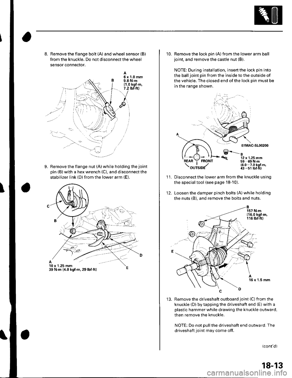
8. Remove the flange bolt {A) andwheel sensor(B)
from the knuckle. Do not disconnect the wheel
sensor conneclor.
Remove the flange nut (A) while holding the joint
pin (B) with a hex wrench (C), and disconnect the
stabilizer link {D) from the lower arm (E).
A5x1.0mm9.8 N.m(1.0 kgl.m,7.2 tbt.ftl
9.
10 x 1.25 mm39 N.m (,1.0 kgf.m,29lbf.ft)
10. Remove the lock pin (A)from the lower arm ball
joint, and remove the castle nut (B).
NOTE: During installation, insert the lock pin into
the balljoint pin from the lnside to the outside of
the vehicle. The closed end of the lock Din must be
in the range shown.
07 MAC-SL00200
€--....-"12 x 1.25 mm59 69N m
'R.
11.
12.
(6.0 7.0 kgl m,43 -51 lbf tt)
Disconnect the lower arm from the knuckle using
the special tool (see page l8-10).
Loosen the damper pinch bolts (A) while holding
the nuts (B), and remove the bolts and nuts.
'13. Remove the driveshaft outboard joint {C) fromthe
knuckle (D) by tapping the driveshaft end (E) with a
plastic hammer while drawing the knuckle outward,
then remove the knuckle.
NOTE: Do not Dull the driveshaft end outward. The
driveshaft joint may come off.
(cont'd)
18-13
Page 575 of 1139
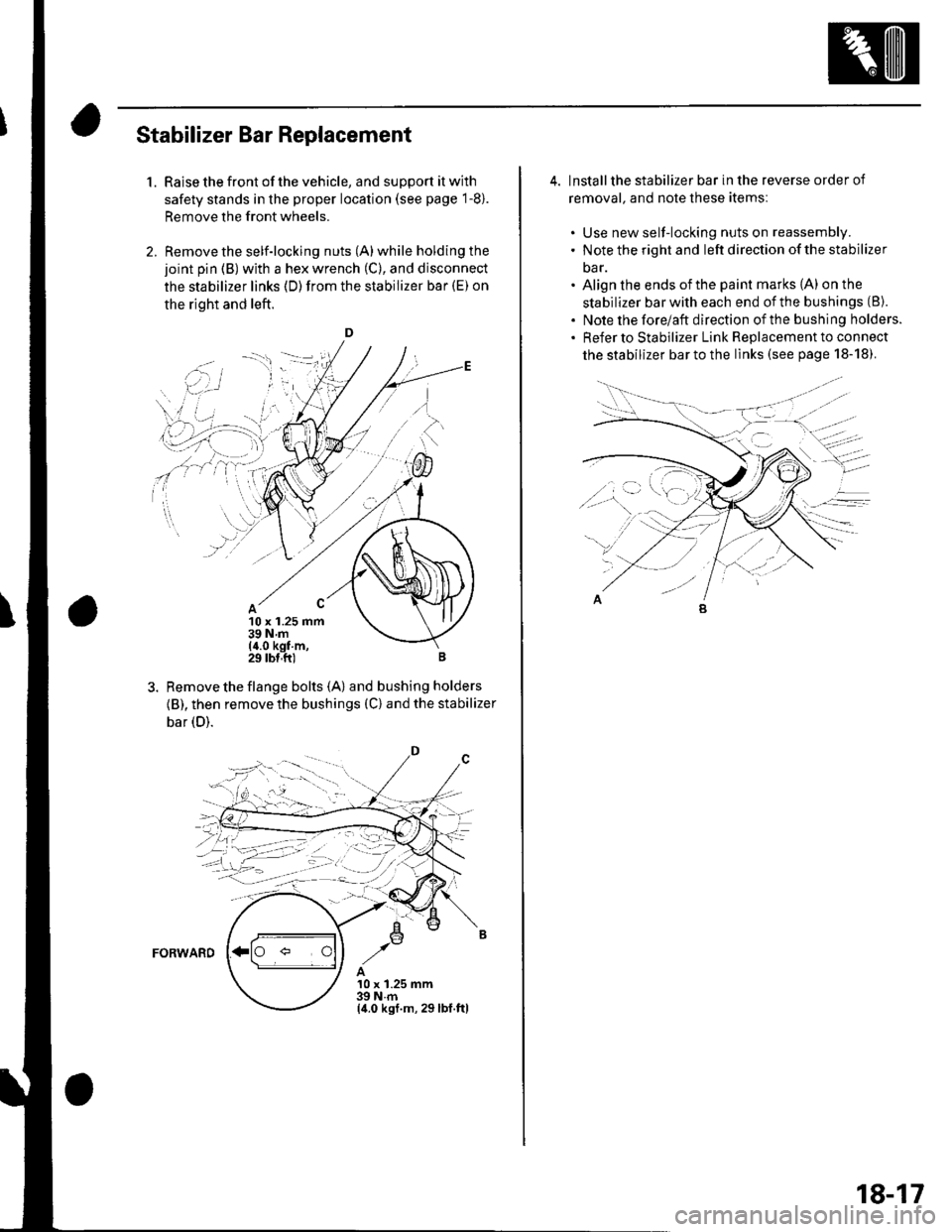
Stabilizer Bar Replacement
1.Raise the front of the vehicle, and support it with
safety stands in the proper location (see page 1-8).
Remove the front wheels.
Remove the self-locking nuts (A) while holding the
joint pin (B) with a hex wrench (C), and disconnect
the stabilizer links (D)from the stabilizer bar (E) on
the right and left.
D
10 x 1.25 mm39Nm(4.0 kgf m,29 tbl,ft)
Remove the flange bolts {A) and bushing holders
{B), then remove the bushings (C) and the stabilizer
bar (D).
FORWARD
A10 x 1.25 mm39Nm(4.0 ksf.m, 29lbl.ftl
,.'i i
''i]
. i.',.:-l I
\' ,r' ,' i :..r'j-- r-'1 _: i'
i-ii::;i
;4-llt,-'j--;
4. lnstallthe stabilizer bar in the reverse order of
removal. and note these itemsl
. Use new self-locking nuts on reassembly.. Note the right and left direction of the stabilizer
oar.. Align the ends ofthe paint marks (A) on the
stabilizer bar with each end of the bushings (8).
. Note the forelaft direction ofthe bushing holders.. Refer to stabilizer Link Replacement to connect
the stabilizer bar to the links (see page 18-18).
18-17
Page 576 of 1139
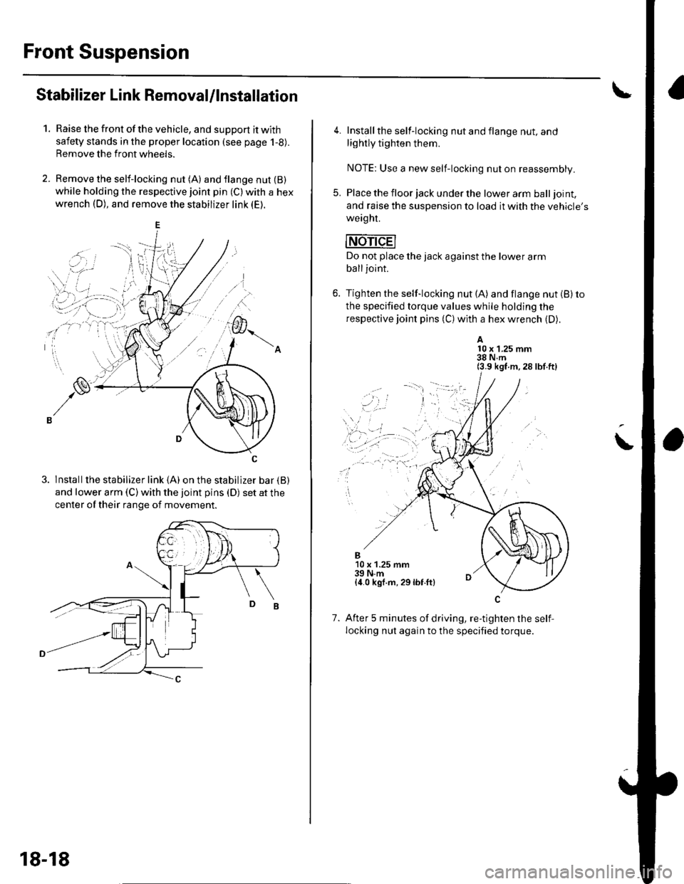
Front Suspension
Stabilizer Link Removal/lnstallation
1.Raise the front of the vehicle, and support it with
safety stands in the proper location (see page 1-8).
Remove the front wheels.
Remove the self-locking nut (A) and flange nut {B)while holding the respective joint pin (C) with a hex
wrench (D), and remove the stabilizer link (E).
3. lnstallthe stabilizer link (A) on the stabilizer bar {B)
and lower arm (C) with the joint pins (D) set at the
center of their range of movement.
18-18
4. Install the self-locking nut and flange nut, and
lightly tighten them.
NOTE: Use a new self-locking nut on reassembly.
5. Place the floor jack under the lower arm balljoint,
and raise the suspension to load it with the vehicle's
weaght.
mri-dEl
Do not place the jack against the lower arm
balljoint.
6. Tighten the self-locking nut (A) and flange nut (B) to
the specified torque values while holding the
respective joint pins (C) with a hex wrench (D).
A10 x 1.25 mm38 N.m(3.9 kgf m,28 lbf.ft)
\
..,
1.
B10 x 1.25 mm39 N.m{4.0 kgf.m, 29lbf.ft}
After 5 minutes of driving, re-tighten the self,
locking nut again to the specified torque.
Page 577 of 1139
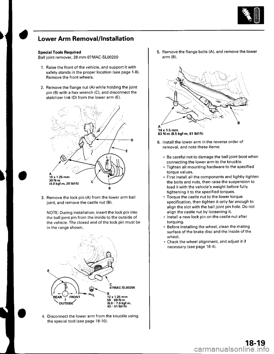
Lower Arm Removal/lnstallation
SpecialTools Required
Ball joint remover,2S mm 07|MAC-S100200
1. Raise the front of the vehicle, and support it with
safety stands in the proper location (see page 1-8).
Remove the front wheels.
Remove the flange nut (A) while holding the joint
pin {B) with a hex wrench (C), and disconnect the
stabilizer link (D)from the lower arm (E).
10 x 1.25 mm39 N.m{4.0 kgf m, 29 lbt.ft)
3.Remove the lock pin (A) from the lower arm ball
joint, and remove the castle nut (B).
NOTE: During installation, insertthe lock pin into
the ball joint pin from the inside to the outside of
the vehicle. The closed end of the lock pin must be
in the range shown.
6--__ oTMAc-sloo2oo
@a12 x 1.25 mm59 69Nm16.0-7.0 kgt-m,43 51 lbf.ft)
4.Disconnect the lower arm from the knuckle using
the special tool (see page 18-10).
5. Remove the flange bolts (A), and remove the lower
arm {B}.
14 x 1.5 mm83 N.m (8.5 kgf.m,61 lbf.ft)
6. Installthe lower arm in the reverse order of
removal, and note these items:
. Be careful not to damage the ball joint boot when
connecting the lower arm to the knuckle.
' Tighten all mounting hardware to the specified
torque values,. Firstinstall all the components and lightlytighten
the bolts and nuts. then raise the suspension to
load it with the vehicle's weight before fully
tightening it to the specified torques.. Torque the castle nut to the lower torque
specification, then tighten it only far enough to
align the slot with the ball joint pin hole. Do not
allgn the castle nut by loosening it.
. Install a new lock pin on the castle nut after
torquing.. Before installing the wheel, clean the mating
surface of the brake disc and the inside of the
wneet.. Check the wheel alignment, and adjustitif
necessary (see page '18-4).
18-19
Page 588 of 1139
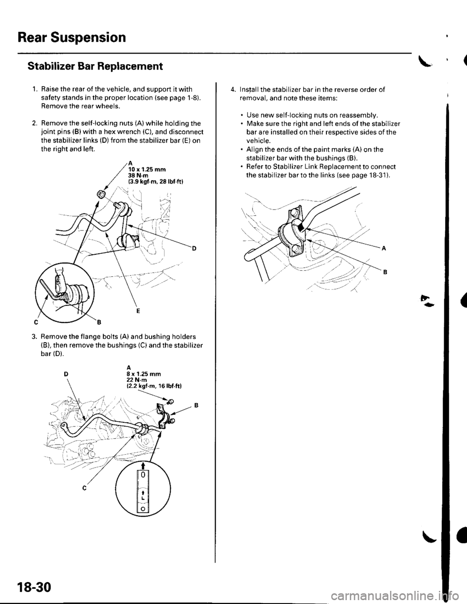
Rear Suspension
1.
Stabilizer Bar Replacement
Raise the rear of the vehicle, and support it with
safety stands in the proper location (see page 1-8).
Remove the rear wheels.
Remove the self-locking nuts (A) while holding thejoint pins (B) with a hex wrench (C), and disconnect
the stabilizer links (D) from the stabilizer bar {E) on
the right and left.
A10 x 1.25 mm38 N.m(3.9 kgf.m,28 lbf.ft)
Remove the flange bolts (A) and bushing holders(B), then remove the bushings {C) and the stabilizer
bar (D).
18-30
4. Inslallthe stabilizer bar in the reverse order of
removal, and note these items:
. Use new self-locking nuts on reassembly.. lMake sure the right and left ends of the stabilizer
bar are installed on their respective sides of the
vehicle.. Align the ends of the paint marks (A) on the
stabilizer bar with the bushings (B).
. Refer to Stabilizer Link ReDlacement to connect
the stabilizer bar to the links {see page 18-31).
Al\.... '..: .
.----'';-r'--\---r-
-tt'.,'t),
(
Page 589 of 1139
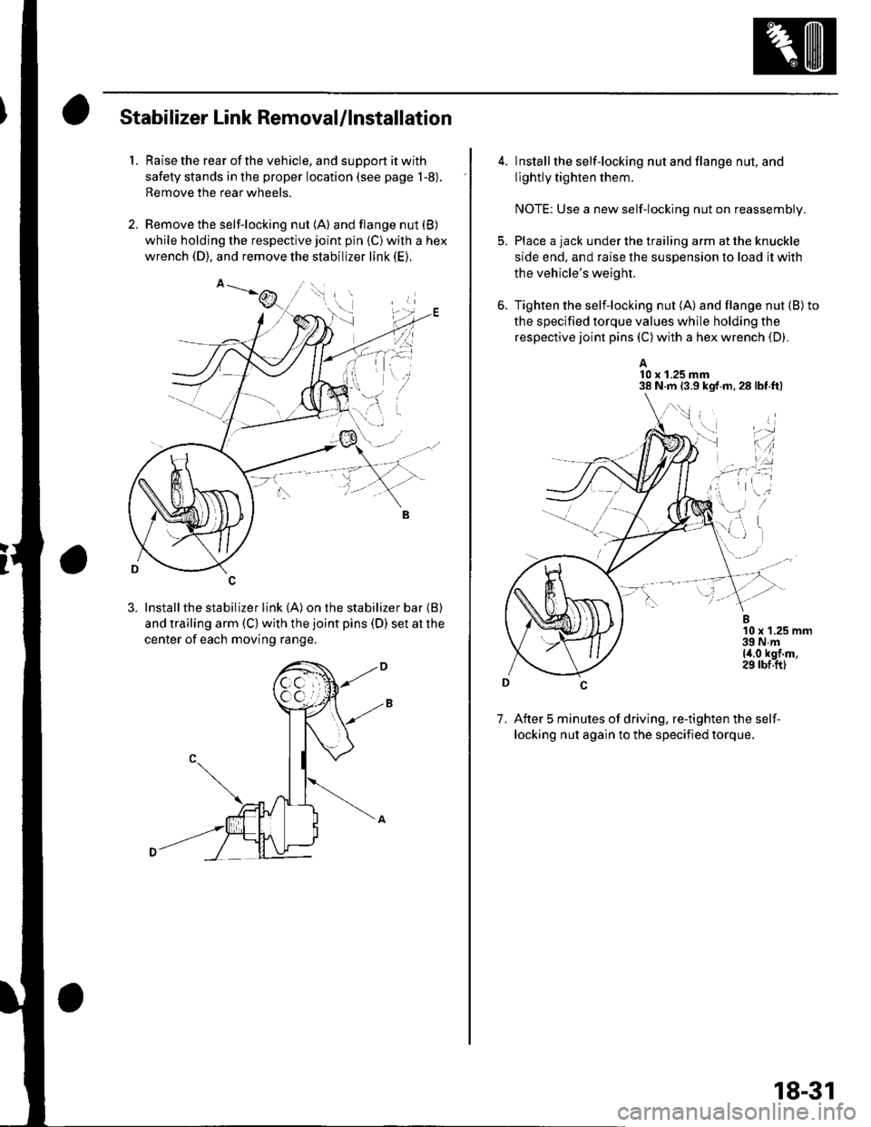
Stabilizer Link Removal/lnstallation
1. Raise the rear of the vehicle, and support it with
safety stands in the proper location (see page 1-8).
Remove the rear wheels.
2. Remove the self-locking nut (A) and flange nut (B)
while holding the respective joint pin {C) wilh a hex
wrench (D), and remove the stabilizer link (E).
3. Installthe stabilizer link (A) on the stabilizer bar {B)
and trailing arm (C) with the joint pins (D) set at the
center of each moving range,
4. lnstall the self-locking nut and flange nut, and
lightly tighten them.
NOTE: Use a new self-locking nut on reassembly.
Place a jack under the trailing arm at the knuckle
side end. and raise the suspension lo load it with
the vehicle's weight.
Tighten the selflocking nut (A) and flange nut {B)to
the specified torque values while holding the
respective joint pins (C) with a hex wrench (D).
A10 x 1.25 mm38 N.m 13.9 kgf.m,28lbf.ftl
7. After 5 minutes of driving, re-tighten the self-
locking nut again to the specified torque.
\,1 i
i'-r d
*l'',:
18-31
Page 591 of 1139
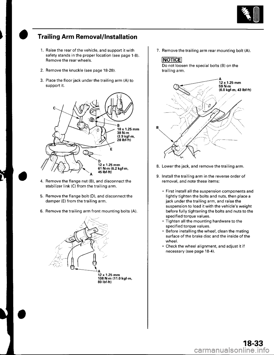
3.
Trailing Arm Removal/lnstallation
1.Raise the rear of the vehicle, and suppon it with
safety stands in the proper location (see page 1,8).
Remove the rear wheels.
Remove the knuckle (see page 18-28).
Place the floor jack under the trailing arm (A) to
support it.
B10 x 1.25 mm38Nm(3.9 kgl.m,28 tbf.ftl
12 x 1.25 mm61 N m (6.2 kgt m.
A 4s tbf,ft)
Remove the flange nut (B), and disconnect the
stabilizer link (C) from the trailing arm.
Remove the flange bolt {D), and disconnect the
damper (E) from the trailing arm.
Remove the trailing arm front mounting bolts (A).
A12 x 1.25 Jnm108 N.m {11.0 kgt.m,80 tbf.ft)
,'a':r -
7. Remove the trailing arm rear mounting bolt (A).
Do not loosen the special bolts (B) on the
trailing arm.
A12 x 1.25 mm59 N.m
-----\':,'.ttg
'.,--1..-r.':1
Lower the jack, and remove the trailing arm.
Install the trailing arm in the reverse order of
removal, and note these items:
. First install allthe suspension components and
lightly tlghten the bolts and nuts, then place ajack under the trailing arm, and raise the
suspension to load it with the vehicle's weight
before fully tightening the bolts and nuts to the
specified torque values.. Tighten allthe mounting hardware to the
specif ied torque values.. Before installing the wheel, clean the mating
surface of the brake disc and the inside of the
wneei.. Check the wheel alignment, and adjust it if
necessary (see page'18-4).
8.
9.
18-33