stabili HONDA CIVIC 2002 7.G Workshop Manual
[x] Cancel search | Manufacturer: HONDA, Model Year: 2002, Model line: CIVIC, Model: HONDA CIVIC 2002 7.GPages: 1139, PDF Size: 28.19 MB
Page 24 of 1139
cont'
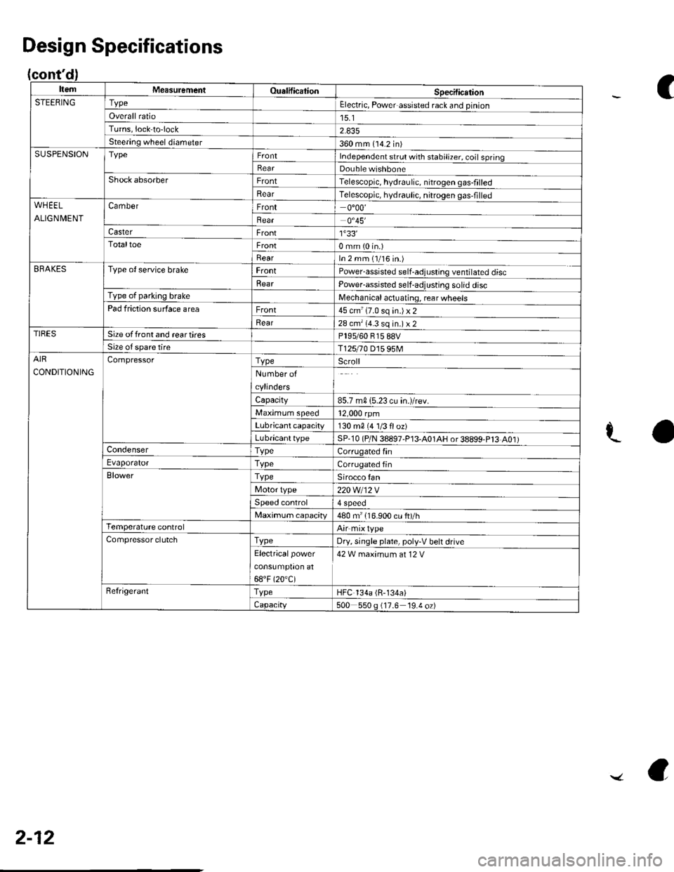
ItemMeasuremeniOualificationSpecilicationSTEERINGTypeElectric, Power assisted rack and pinion
Overall ratio15.1Turns,lock to-lock
Steering wheel diameter360 mm (14.2 in)SUSPENSIONTypeIndependent srrul with stabiliTer. coil springRearDouble wishboneShock absorberFrontTelescopic, hydraulic. nitrogen gas-frlled
RearTelescopic, hydraulic, nitrogen gas,filledWHEEL
ALIGNMENT
CamberFront0"00'
Bear0.45'�
CasterFront1'33'�TotaltoeFront0 mm (0 in.)
RearIn 2 mm (1/16 in.)BRAKESType of service brakeFrontPowerassisted self-adjusling ventilated disc
BearPower-assisted self-adjusting solid discType of parking brakeMechanical actuating, rear wheelsPad friction surface areaFront45 cm'(7.0 sq in.)x2
Rear28 cm'(4.3 sq in.) x 2TIRESSize offront and reartiresPl95/60 815 88VSize o{ spare tireT125r0 D15 95MAIR
CONDITIONING
CompressorTypeScroll
Number of
cylinders
Capacity85.7 m015.23 cu in.)/rev.
Maximum speed12,000 rpm
Lubricant capacity130 m0 {4 1/3 floz)
LubricanttypeSP-10 (P/N 38897'P13-A01AH or38899-P13 A01)CondenserTypeCorrugated finEvaporatorTvpeCorrugated fin
BlowerTypeSirocco fan
Motor type220 Wl12 V
Speed control4 Speeo
Maximum capacity480 m" 116.900 cu ft)/hTemperature controlAirmixtype
Compressor clutchTvpeDry, single plate, poly-V belt drive
Electricalpower
cons!mptron at
68"F (20.C)
42 W maximum at 12 V
RefrigerantTypeHFC 134a (R-134a)
Capacity500 550 g (17.6 19.4 oz)
Design Specifications
C
aL
2-12
../ a
Page 85 of 1139
18.
19.
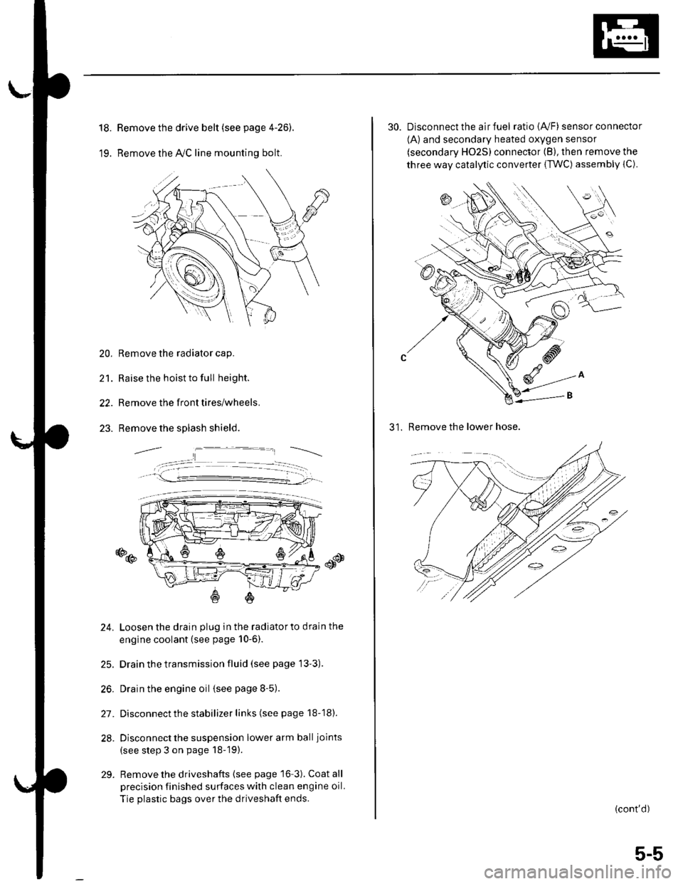
Remove the drive belt (see page 4-26).
Remove the lvC line mounting bolt.
20. Remove the radiator cap.
21. Raise the hoist to full height.
22. Remove the front tires/wheels.
23. Remove the splash shield.
o@
24. Loosen the drain plug in the radiatorto drain the
engine coolant (see page 10-6).
25. Drain the transmission fluid (see page 13'3).
26. Drain the engine oil {see page 8-5).
27. Disconnect the stabilizer links (see page 18-18).
28. Disconnect the suspension lower arm ball joints
(see step 3 on page 18-19).
29. Remove the driveshafts {see page 16-3). Coat all
precision finished surfaces with clean engine oil.
Tie plastic bags over the driveshaft ends.
30. Disconnect the air fuel ratio {4,/F) sensor connector
(A) and secondary heated oxygen sensor
(secondary HO2S) connector (B), then remove the
three way catalytic converter {TWC) assembly {C).
31. Remove the lower hose.
(cont'd)
5-5
Page 92 of 1139
Engine Assembly
18.
Engine Installation {cont'dl
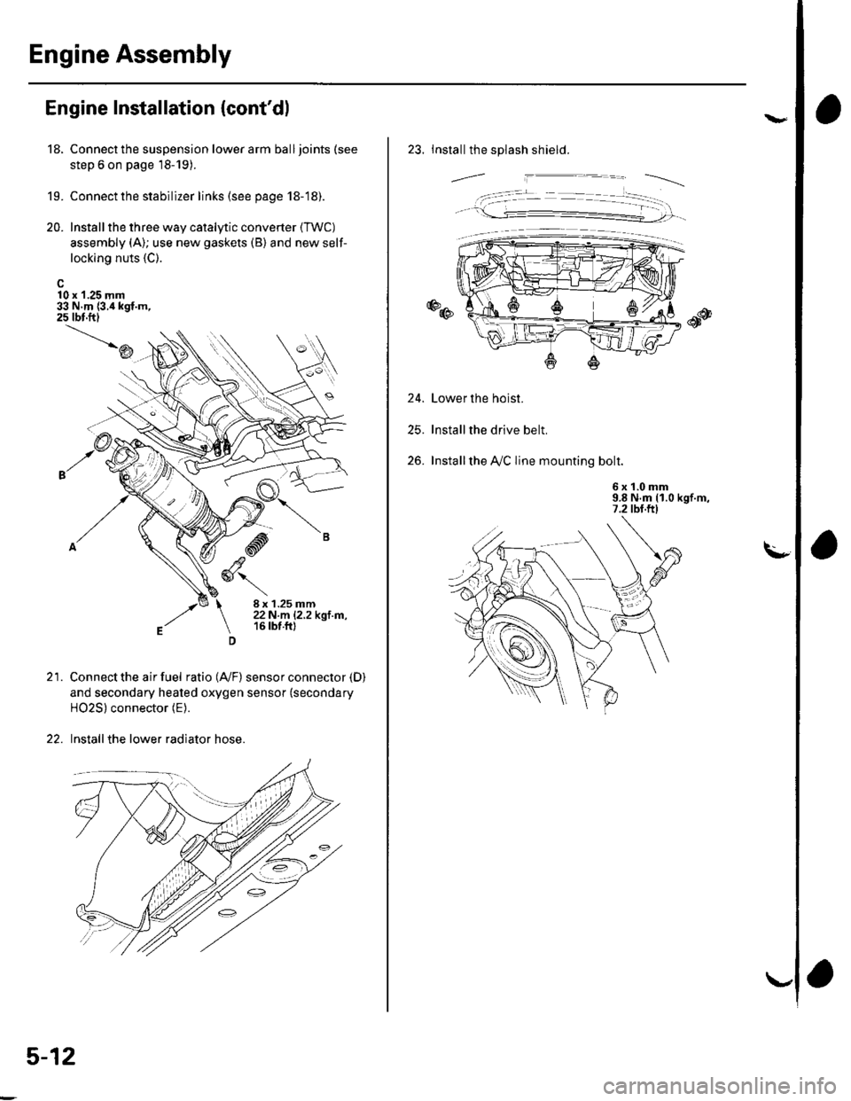
10 x 1.25 mm33 N.m {3.i1kgf.m,25 tbt.ftl
19.
20.
Connect the suspension lower arm ball joints (see
step 6 on page 18-19).
Connect the stabilizer links (see page 18-18).
Install the three way catalytic converter (TWC)
assembly (A); use new gaskets (B) and new self-
locking nuts {C).
\D
21.
-d
,ry6\
8 x 1.25 mm22N.m |.2.2kgl m,16 tbt.ft)
Connect the air fuel ratio (4,/F) sensor connector (D)
and secondary heated oxygen sensor (secondary
HO2S) connector (E).
Install the lower radiator hose.
5-12
va
23. Installthe splash shield.
24.
25.
26.
Lower the hoist.
Installthe drive belt.
Installthe A,/C line mounting bolt.
6 x '!.0 mm9.8 N.m (1.0 kgf.m,7.2 tbt.ftl
. -t- --�- --�--r
Page 235 of 1139
Fuel and Emissions Systems
(
(
(
System Descriptions (cont'dl
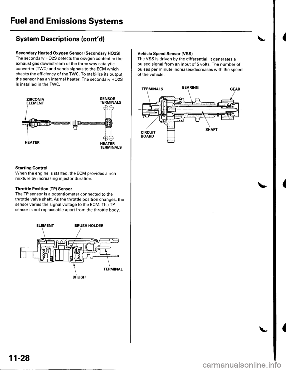
Secondary Heated Oxygen Sensor (Secondary HO2S)
The secondary HO2S detects the oxygen content in the
exhaust gas downstream of the three way catalytic
converter (TWC) and sends signals to the ECM which
checks the efficiency of the TWC. To stabilize its output,
the sensor has an internal heater. The secondarv HO2S
is installed in the TWC.
ztRcoNtaELEMENTSENSORTERMINALS
HEATERTERMINALS
Starting Control
When the engine is started, the ECM provides a rich
mixture by increasing injector duration.
Throttle Position ITP) Sensor
The TP sensor is a potentiometer connected to the
throttle valve shaft. As the throttle position changes, the
sensor varies the signal voltage to the ECM. The TP
sensor is not replaceable apart from the throftle body.
ELEMENTBRUSH HOLDER
gRUSH
11-28
Vehicle Speed Sensor (VSS)
The VSS is driven by the differential. lt generates apulsed signal from an input of 5 volts. The number ofpulses per minute increases/decreases with the speed
of the vehicle.
BEARING
Page 237 of 1139
Fuel and Emissions Systems
(System Descriptions (cont'dl
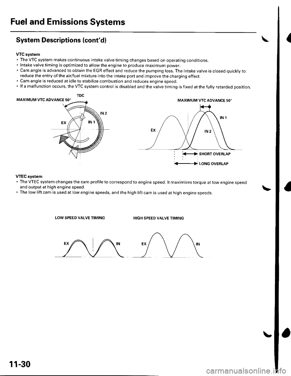
VTC system. The VTC system makes continuous intake valve timing changes based on operating conditions.. Intake valve timing is optimized to allow the engine to produce maximum power.'CamangleisadvancedtoobtaintheEGReffectandreducethepumpingloss.Theintakevalveisclosedquicklyto
reduce the entry of the airlfuel mixture into the intake port and improve the charging effect.. Cam angle is reduced at idle to stabilize combustion and reduces engine speed.'lfamalfunctionoccurs,theVTCsystemcontrol is disabled and the valve timing is fixed at the fully retarded position.
MAXIMUM VTC ADVANCE 50'
i l(-4 sHoRT oVERLAP
'+-|l LoNG oVERLAP
VTEC system' The VTEC system changes the cam profile to correspond to engine speed. lt maximizes torque at low engine speedand output at high engine speed.. The low lift cam is used at low engine speeds, and the high lift cam is used at high engine speeds.
LOW SPEED VALVE TIMINGHIGH SPEED VALVE TIMING
TDC
MAXIMUM VTC ADVANCE 50'
11-30
Page 393 of 1139
EVAP System
EVAP Two Way Valve Test
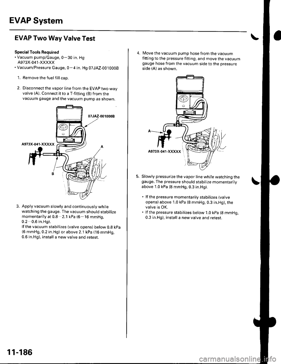
Special Tools Required. Vacuum pump/Gauge,0-30 in. Hg
A973X-041-XXXXX. Vacuum/Pressure cauge.0-4 in. Hg 07JAZ-0010008
1. Remove the fuelfill cap.
2. Disconnect the vapor line from the EVAP two wayvalve (A). Connect it to a T-fitting (B) from thevacuum gauge and the vacuum pump as shown,
07JAZ-0010008
Apply vacuum slowly and continuously while
watching the gauge. The vacuum should stabilize
momentarily at 0.8 2.1 kPa (6 16 mmHg,
0,2 0.6 in.Hg).
lf the vacuum stabilizes {valve opens) below 0.8 kpa(6 mmHg,0.2 in.Hg) or above 2.1 kPa (16 mmHg,
0.6 in.Hg), install a new valve and retest.
11-186
4. Move the vacuum pump hose from the vacuumfitting to the pressure fitting, and move the vacuumgauge hose from the vacuum side to the pressure
side (A) as shown.
Slowly pressurize the vapor line while watching thegauge. The pressure should stabilize momentarilV
above 1.0 kPa (8 mmHg, 0.3 in.Hg).
. lfthe pressure momentarily stabilizes (valve
opens) above 1.0 kPa (8 mmHg,0.3 in.Hg), thevalve is OK.. lf the pressure stabilizes below 1.0 kPa (8 mmHg,
0.3 in.Hg), install a new valve and retest.
Page 470 of 1139
Driveshaft Inspection
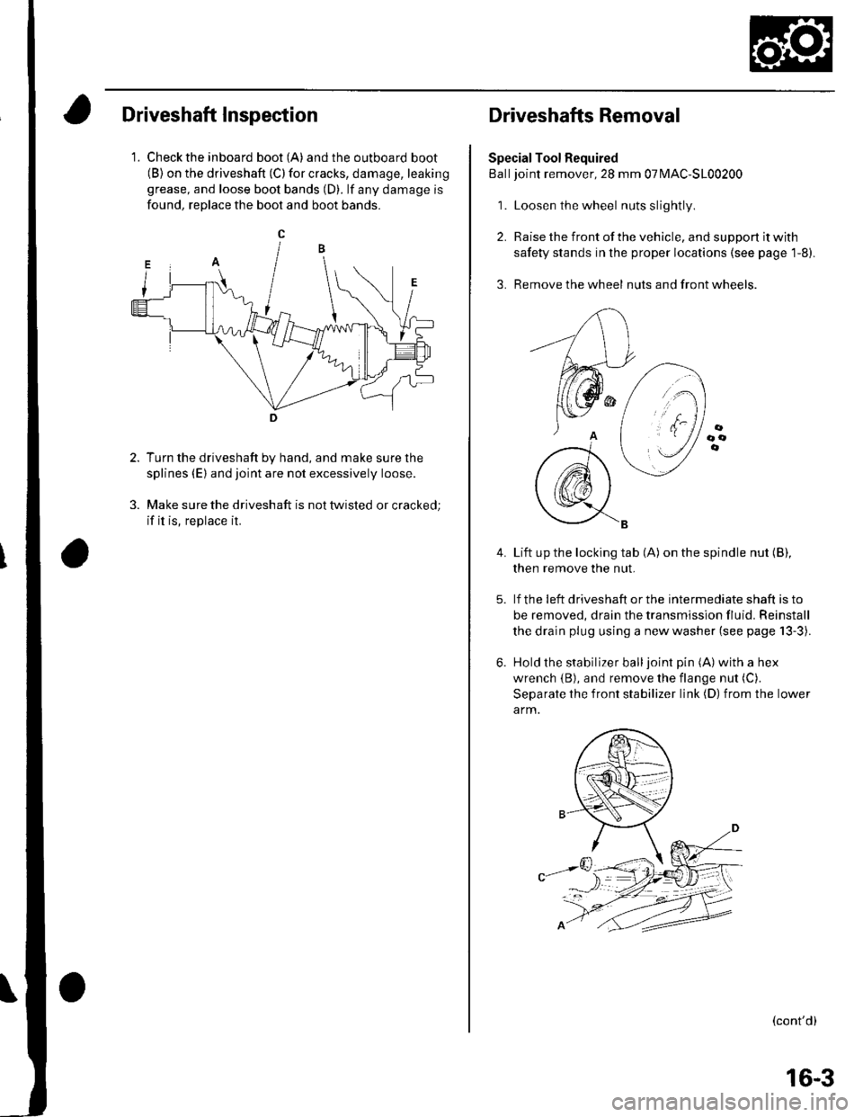
1. Check the inboard boot (A) andthe outboard boot(B) on the driveshaft (C) for cracks, damage, leaking
grease, and loose boot bands (D). lf any damage is
found, reDlace the boot and boot bands.
Turn the driveshaft by hand, and make sure the
splines (E) and joint are not excessively loose.
Make sure the driveshaft is not twisted or cracked;
if it is, replace it.
Driveshafts Removal
Special Tool Required
Balljoint remover, 28 mm 07MAC-S100200
1. Loosen the wheel nuts slightly
2. Raise the front of the vehicle, and support it with
safety stands in the proper locations (see page 1-8).
3. Remove the wheel nuts and front wheels.
4.Lift up the locking tab (A) on the spindle nut (B),
then remove the nut.
lf the !eft driveshaft or the intermediate shaft is to
be removed, drain the transmission fluid. Reinstall
the drain plug using a new washer (see page 13-3).
Hold the stabilizer balljoint pin (A) with a hex
wrench {B), and remove the flange nut (C).
Separate the front stabilizer link (D) from the lower
a rm.
(cont'd)
16-3
Page 485 of 1139
Driveline/Axle
Driveshafts Installation (cont'd)
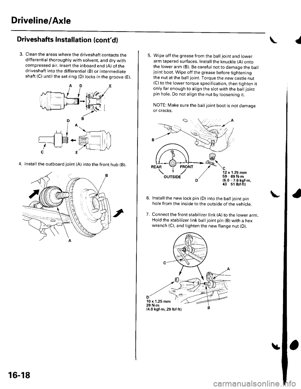
Clean the areas where the driveshaft contacts thedifferential thoroughly with solvent, and dry withcompressed air. Insenthe inboard end {A) ofthedriveshaft into the differential (B) or intermediateshaft {C) until the set ring (D) locks in the groove (E).
4. Install the outboard joint (A) into the front hub (B).
16-18
5. Wipe offthe grease from the ball ioint and lowerarm tapered surfaces. Installthe knuckle (A) ontothe lower arm {B). Be careful not to damage the balljoint boot. Wipe off the grease before tighteningthe nut at the ball joint. Torque the new castle nut(C) to the lower torque specification, then tighten itonly far enough to align the slot with the ball joint
pin hole. Do not align the nut by loosening it.
NOTE: Make sure the ball joint boot is not damageor cracks.
"-'t-
12 x 1.25 mm59 69 N.m(6.0 -7.0 kgf m,43 51 tbt.ftl
Installthe new lock pin {D) into the balljoint pin
hole from the inside to the outside of the vehicle.
Connect the front stabilizer link {A) to the lower arm.Hold the stabilizer link balljoint pin (B) with a hexwrench {C), and tighten the newflange nut {D).
7.
'10 x 1.25 mm39 N.m{4.0 kgf.m,29 lbf.ft)
{
Page 559 of 1139
Suspension
Front and Rear Suspension
SpecialTools ............. 18-2
Component Location Index ......................................... 18-3
Wheel Alignment ..................... ........... 18-4
Wheel Bearing End Play Inspection ............................ 18-8
Wheel Runout Inspection .................. 18-9
Ball Joint Removal ... 18-10
Front Suspension
Kn uckle/H u bAVheel Bearing Replacement
Ball Joint Boot Reolacement ..................
Stabilizer Bar Rep|acement ....................
Stabilizer Link Removal/lnstallation
LowerArm Removal/lnstallation ...............
Damper/Spring Replacement
Rear Suspension
Hub Bearing Unit Replacement .....................
Knuckle Reolacement
Stabilizer Bar Replacement ....................
Stabilizer Link Removal/lnstallation ..........................
Upper Arm Removal/lnstallation ...............
Trailing Arm Removal/lnstallation
Damper/Spring Replacement
18-1 1
18-16
18-17
18-18
18-19
18-20
18-26
18-28
18-30
18-31
18-32
18-33
18-34
Page 561 of 1139
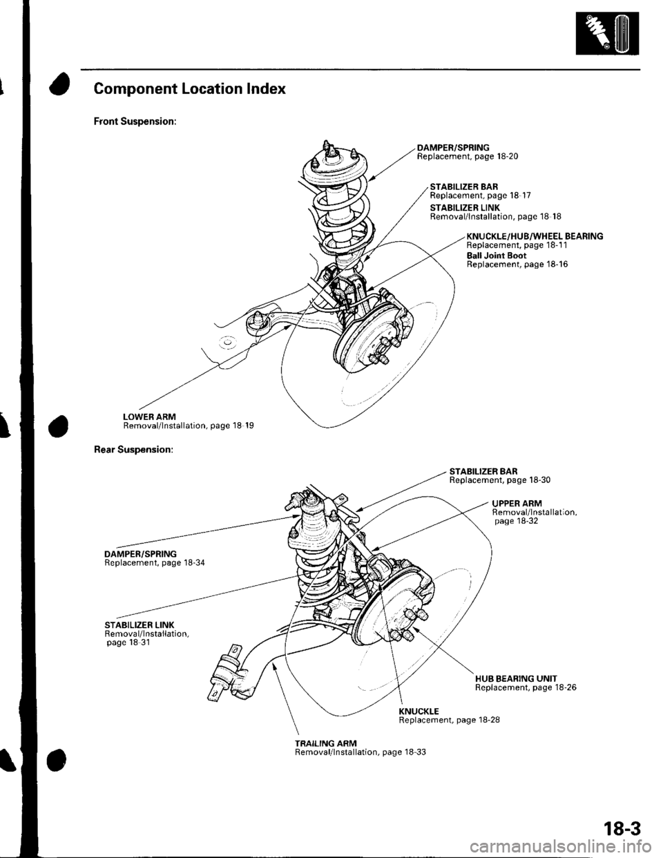
Component Location Index
Front Suspension:
LOWEB ARMRemoval/lnstallation, page 18 19
Rear Suspension:
DAMPER/SPRINGReplacement, page'18-34
DAMPER/SPRINGReplacement, page 18-20
STABILIZER BARReplacement, page 18-17
STABILIZER LINKRemoval/lnstallation, page 18 18
STABILIZER BARReplacement. page 18-30
KNUCKLE/HU8/WHEEL BEARINGReplacement, page 18-1 1
Ball Joint BootReplacement, page'18-16
UPPER ARMRemoval/lnstallation,page'18-32
HUB BEARING UNITReplacement, page 18'26
KNUCKLEReplacement, page 18-28
TRAILING ARMRemoval/lnstallation, page 18 33
18-3