dtc HONDA CIVIC 2002 7.G Workshop Manual
[x] Cancel search | Manufacturer: HONDA, Model Year: 2002, Model line: CIVIC, Model: HONDA CIVIC 2002 7.GPages: 1139, PDF Size: 28.19 MB
Page 1102 of 1139
)
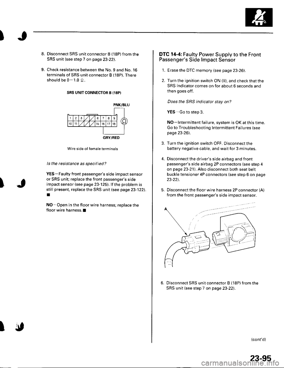
8. Disconnect SRS unit connector B (18P)from the
SRS unit (see step 7 on page 23-221.
9. Check resistance between the No.9 and No. 16
terminals of SRS unit connector B (18P). There
should be 0-1.0 S2.
SRS UNIT CONNECTOR B {18PI
PNK/BLU
t-
l-u5l niFf;l \
230
10t1t5
T
GRY/RED
Wire side ol lemale terminals
ls the resistance as specified?
YES-Faulty front passenger's side impact sensor
or SRS unit; replace the front passenger's side
impact sensor (see page 23-125). lf the problem is
still present, replace the SRS unit (see page 23-122).
I
NO-Open in the floor wire harness; replace the
floor wire harness. !
I
DTC 14-4: Faulty Power Supply to the Front
Passenger's Side lmpact Sensor
1. Erase the DTC memory (see page 23-26).
2. Turn the ignition switch ON (ll), and check that the
SRS indicator comes on for about 6 seconds and
then goes off.
Does the SRS indicator stay on?
YES-Go to step 3.
NO-lntermittent failure, system is OK at this time.
Go to Troubleshooting Intermittent Failures (see
page 23-261.
3. Turn the ignition switch OFF. Disconnect the
battery negative cable, and wait for 3 minutes.
4. Disconnectthe driver's side airbag and front
passenger's side airbag 2P connectors (see step 4
on page 23-21). Also disconnect both seat belt
buckle tensioner 4P connectors (see step 6 on page
23-22t.
5. Disconnect the floor wire harness 2P connector {A}from the front passenger's side impact sensor.
Disconnecl SRS unit connector B (18P) from the
SRS unit (see step 7 on page 23-22i.
(cont'd)
"-;s.\
/ \--) frl l 1
- F.,=
j
23-95
Page 1103 of 1139
sRs
DTG Troubleshooting (cont'd)
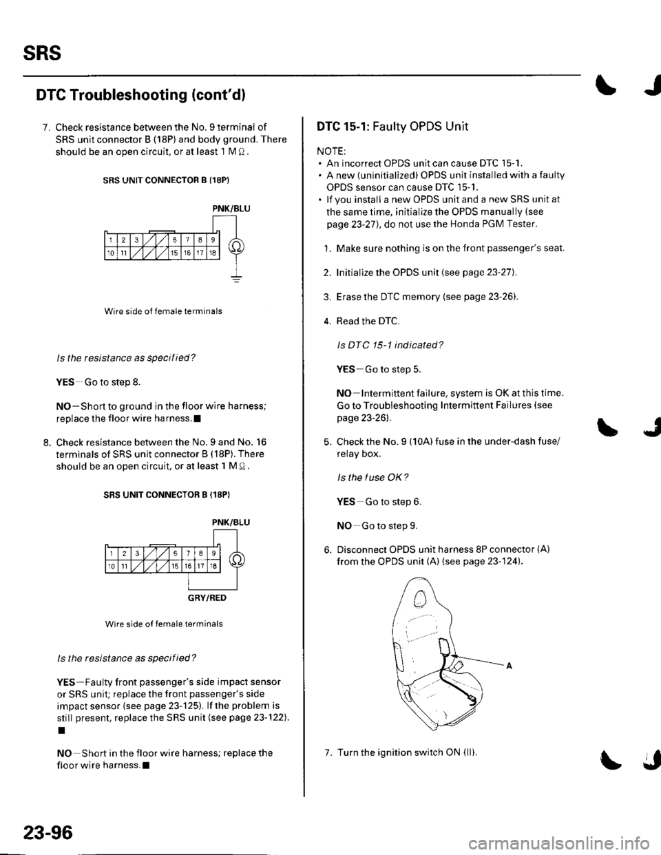
7. Check resistance between the No. 9 terminal of
SRS unit connector B (18P) and body ground. There
should be an ooen circuit, or at least 1 N4 Q.
SRS UNIT CONNECTOR B {18PI
Wire side of female terminals
ls the tesistance as specilied?
YES Go to step 8.
NO-Short to ground in the floor wire harness;
replace the floor wire harness.l
Check resistance between the No.9 and No. 16
terminals of SRS unit connector B (18P). There
should be an open circuit, or at least 1 M O .
SRS UNIT CONNECTOR B (18P)
PNK/BLU
_-r'18 sl /itltlis-l \
236
10tl
GRY/RED
Wire side ot female terminals
ls the resistance as specified?
YES-Faulty front passenger's side impact sensor
or SRS unit; replace the front passenger's side
impact sensor {see page 23-125). lf the problem is
still present, replace the SRS unit (see page 23-122).
I
NO Short in the floor wire harness; replace the
floor wire harness.l
PNK/BLU
23-96
7. Turn the ignition switch ON (ll).
DTC 15-1: Faulty OPDS Unit
NOTE:. An incorrect OPDS unit can cause DTC 15-1.. A new (uninitialized) OPDS unit installed with a faulty
OPDS sensor can cause DTC 15-1.. lf you install a new OPDS unit and a new SRS unit at
the same time, initialize the OPDS manually (see
page 23-27), do not use the Honda PGM Tester.
1. Make sure nothing is on the front passenger's seat.
2. Initialize the OPDS unit (see page 23-27).
3. Erase the DTC memory (see page 23-26]'.
4. Read the DTC.
Is DTC 15-1 indicated?
YES Go to step 5.
NO Intermittent failure, system is OK at this time.
Go to Troubleshooting Intermittent Failures (see
page 23-26).
Check the No. 9 (10A) fuse in the under-dash fuse/
relay Dox,
ls the tuse OK?
YES Go to step 6.
NO Go to step 9.
Disconnect OPDS unit harness 8P connector (A)
from the OPDS unit (A) (see page 23-124).
Page 1105 of 1139
sRs
18.
19.
20.
DTC Troubleshooting (cont'dl
Turn the ignition switch OFF. Disconnect the
battery negative cable. and wait for 3 minutes.
Disconnect both side airbag connectors (see step 4
on page 23-21)and both seat belt buckletensioner
4P connectors (see step 6 on page 23-22).
Disconnect SRS unit connector B (18P) from the
SRS unit (see step 7 on page 23-221.
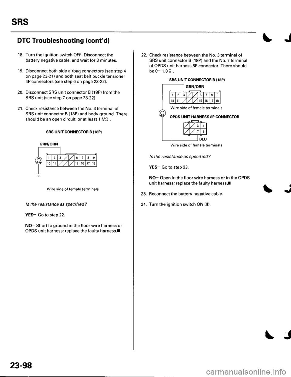
Check resistance between the No. 3 terminal of
SRS unit connector B (18P) and body ground. There
should be an oDen circuit, or at least 1 MQ .
SRS UNIT CONNECTOR B I18PI
Wire side ot temale terminals
ls the resistance as specified?
YES- Go to step 22.
NO Short to ground in the floor wire harness or
OPDS unit harness; replace the faulty harness.l
GRN/ORN
23-98
22. Check resistance between the No. 3 terminal of
SRS unit connector B (18P) and the No. 7 terminal
of OPDS unit harness 8P connector. There should
be0 1.0Q.
SRS UNIT CONNECTOR B (18PI
GRN/ORN
Wire side of female terminals
OPOS UNIT HARNESS 8P CONNECTOR
24.
BLU
Wire side of female terminals
ls the resistance as specitied?
YES Go to step 23.
NO Open in the floor wire harness or in the OPDS
unit harness; replace the faulty harnessl
Reconnect the baftery negative cable.
Turn the ignition switch ON (ll).
Page 1106 of 1139
J
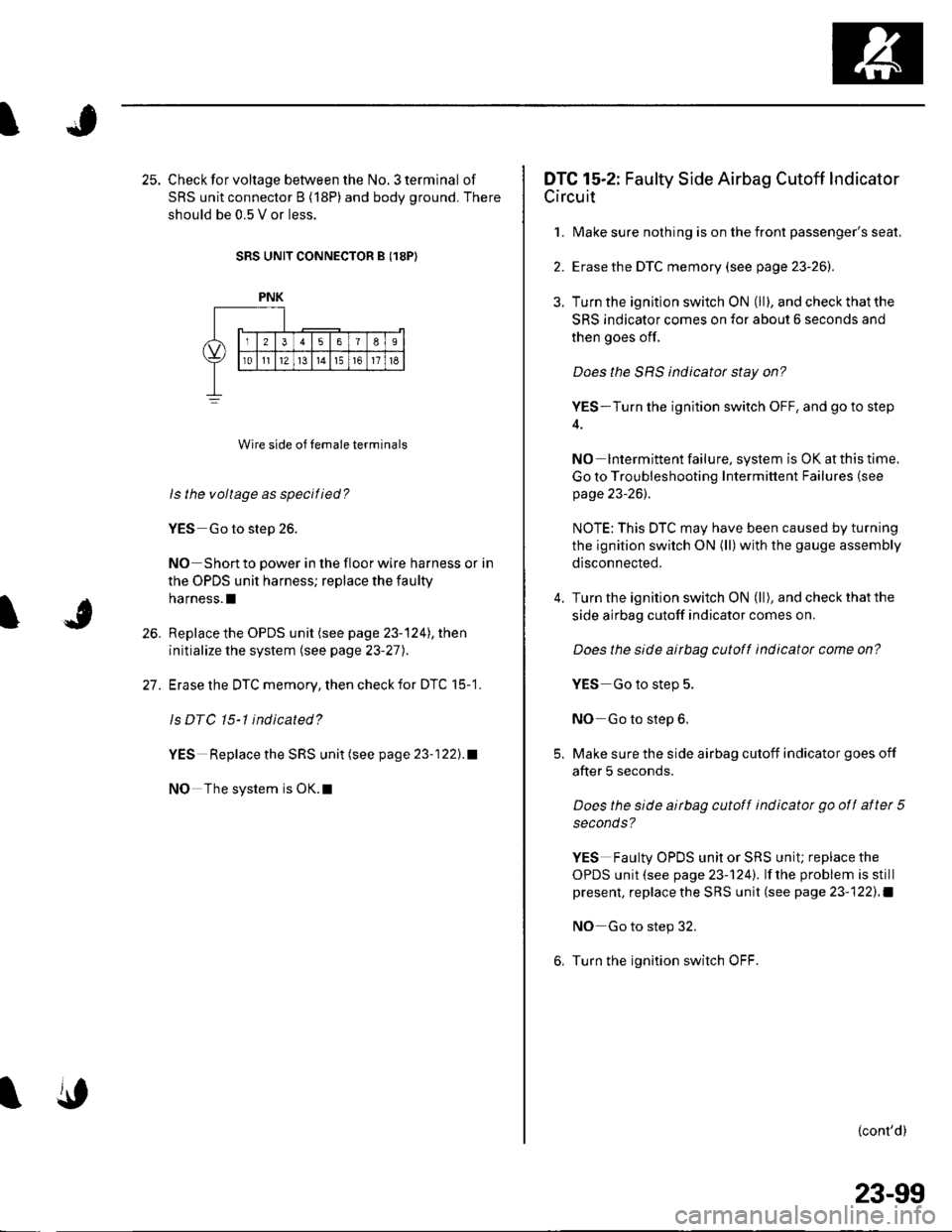
25. Check for voltage between the No. 3 terminal of
SRS unit connector B (18P) and body ground. There
should be 0.5 V or less.
SRS UNIT CONNECTOR B (18P)
Wire side of temale terminals
ls the voltage as specilied?
YES Go to step 26.
NO Short to power in the floor wire harness or in
the OPDS unit harness; replace the faulty
harness.l
Replace the OPDS unit (see page 23-'124), then
initialize the system (see page 23-27).
Erase the DTC memory, then check for DTC 15-1.
ls DTC 15-l indicated?
YES Replace the SRS unit (see page 23-122).1
NO The system is OK.l
26.
27.
PNK
DTC 15-2: Faulty Side Airbag Cutoff Indicator
Circuit
1. Make sure nothing is on the front passenger's seat.
2. Erase the DTC memory (see page 23-26]-.
3. Turn the ignition switch ON (ll),andcheckthatthe
SRS indicator comes on for about 6 seconds and
then goes off.
Does the SRS indicator stay on?
YES-Turn the ignition switch OFF, and go to step
NO Intermittent failure, system is OK at this time.
Go to Troubleshooting Intermittent Failures (see
page 23-26).
NOTE:This DTC may have been caused by turning
the ignition switch ON (ll)with the gauge assembly
disconnected.
Turn the ignition switch ON (ll), and checkthatthe
side airbag cutoff indicator comes on.
Does the side airbag cutoft indicator come on?
YES Go to step 5.
NO Go to step 6.
Make sure the side airbag cutoff indicator goes off
after 5 seconds.
Does the side airbag cutoff indicator go otf after 5
seconds?
YES Faulty OPDS unit or SRS uniu replace the
OPDS unit (see page 23-1241. lf the problem is still
present, replace the SRS unit (see page 23-122).)
NO Go to step 32.
Turn the ignition switch OFF.
{cont'd)
23-99
Page 1107 of 1139
sRs
DTC Troubleshooting (cont'd)
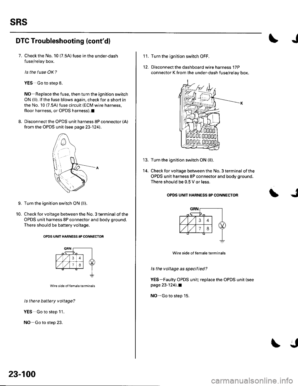
7. Check the No. 10 (7.5A)fuse in the under-dash
fuse/relay box.
ls the f use OK?
YES Go to step 8.
NO Replace the fuse, then turn the ignition switch
ON (ll). lf the fuse blows again, check for a short in
the No. 10 {7.5A) fuse circuit (ECM wire harness.
floor harness, or OPDS harness).1
8. Disconnect the OPDS unit harness 8P connector (A)
from the OPDS unit (see page 23-124).
Turn the ignition switch ON (ll).
Check for voltage between the No. 3 terminal of the
OPDS unit harness 8P connector and body ground.
There should be battery voltage.
OPDS UNtT HARNESS 8P CONNECTOR
Wire side of female terminals
ls there battety voltage?
YES Go to step 11.
NO Go to step 23.
9.
10.
23-100
11.
12.
14.
Turn the ignltion switch OFF.
Disconnect the dashboard wire harness 17P
connector K from the under-dash fuse/relay box,
Turn the ignition switch ON (ll).
Check for voltage between the No. 3 terminal of the
OPDS unit harness 8P connector and body ground.
There should be 0.5 V or less.
OPDS UNIT HABNESS 8P CONNECTOR
Wire side of lemale terminals
ls the voltage as specitied?
YES-Faulty OPDS unit; replace the OPDS unit (see
page 23-124) .a
NO-Go to step 15.
Page 1109 of 1139
sRs
23.
24.
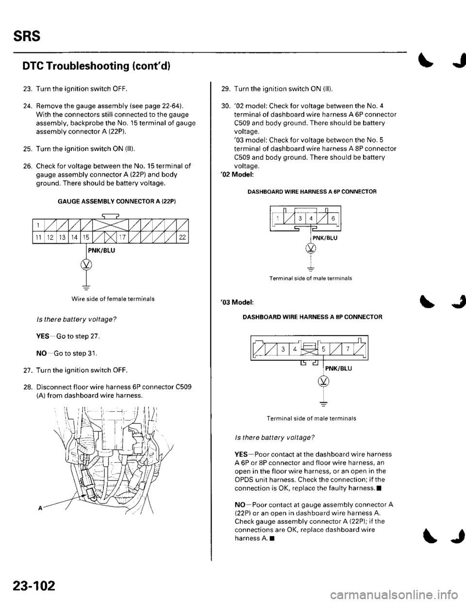
DTC Troubleshooting (cont'dl
Turn the ignition switch OFF.
Remove the gauge assembly (see page 22-64l,.
With the connectors still connected to the gauge
assembly, backprobe the No. '15 terminal of gauge
assembly connector A (22P).
Turn the ignition switch ON {ll).
Check for voltage between the No. 15 terminal of
gauge assembly connector A {22P) and body
ground. There should be battery voltage.
GAUGE ASSEMBLY CONNECTOR A {22P)
Wire side of female terminals
ls thete battery voltage?
YES-Go to step 27.
NO Go to step 31.
Turn the ignition switch OFF.
Dlsconnect floor wire harness 6P connector C509
{A) from dashboard wire harness.
26.
27.
28.
23-102
\J
29. Turn the ignition switch ON (lli
30. '02 model: Checkforvoltage between the No.4
terminal of dashboard wire harness A 6P connector
C509 and body ground. There should be battery
vorlage.'03 model: Check for voltage between the No. 5
terminal of dashboard wire harness A 8P connector
C509 and body ground. There should be battery
vollage.'02 Model:
OASHBOARD WIRE HARNESS A 6P CONNECTOF
Terminal side of male terminals
'03 Model:
DASHBOARD WIRE HARNESS A 8P CONNECTOR
Terminal side of male terminals
ls there battety voltage?
YES Poor contact at the dashboard wire harness
A 6P or 8P connector and floor wire harness, an
open in the floor wire harness, or an open in the
OPDS unit harness. Check the connection; if the
connection is OK, replace the faulty harness.l
NO Poor contact at gauge assembly connector A
{22P) or an open in dashboard wire harness A.
Check gauge assembly connector A {22P); if the
connections are OK, replace dashboard wire
harness A.I
Page 1111 of 1139
sRs
DTG Troubleshooting (cont'dl
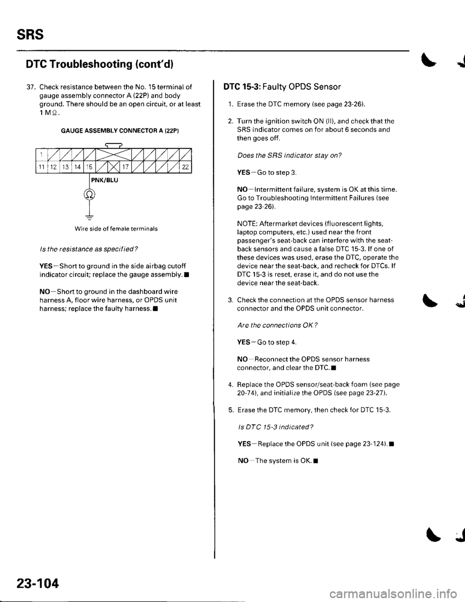
37. Check resistance between the No. 15 terminal of
gauge assembly connector A (22P) and body
ground. There should be an open circuit, or at least
1M0.
GAUGE ASSEMBLY CONNECTOR A I22PI
ls the resistance as specified?
YES-Short to ground in the side airbag cutoff
indicator circuit; replace the gauge assembly.l
NO Short to ground in the dashboard wire
harness A, floor wire harness, or OPDS unit
harness; replace the faulty harness.l
Wire side of female terminals
23-104
J
DTC 15-3: Faulty OPDS Sensor
1. Erase the DTC memory {see page 23-261.
2. Turn the ignition switch ON (ll), and check that the
SRS indicator comes on for about 6 seconds and
then goes off.
Does the SRS indicator stay on?
YES-Go to step 3.
NO Intermittent failure, system is OK at this time.
Go to Troubleshooting Intermittent Failures (see
page 23-26).
NOTE: Aftermarket devices (fluorescent lights,
laptop computers, etc.) used near the front
passenger's seat-back can interfere with the seat-
back sensors and cause a false DTC 15-3. lf one of
these devices was used, erase the DTC, operate the
device near the seat-back, and recheck for DTCs. lf
DTC 15-3 is reset, erase it, and do not use the
device near the seat-back.
3.
4.
Check the connection at the OPDS sensor harness
connector and the OPDS unit connector.
Are the connections OK?
YES-Go to step 4.
NO Reconnect the OPDS sensor harness
connector, and clear the DTC.I
Replace the OPDS sensor/seat-back foam (see page
20-141, and initialize the OPDS (see page 23-27).
Erase the DTC memory, then check for DTC 15-3.
ls DTC 15-3 indicated?
YES Replace the OPDS unit (see page 23-1241.a
NO The system is OK.l
{
Page 1114 of 1139
JI
I
The SRS lndicator Stays On When ln "SCS"
Menu Method
NOTE:. lf you cannot retrieve DTCSwith the PGM Tester
using the SRS menu method. retrieve the flash codeswith the Tester in SCS mode {see page 23-24|,.. A new SRS unit must sense the entire system is OK
before completing its initial self-test. The most
common cause of an incomplete self-test is the
failure to replace all deployed parts after a collision,
in particular, seat belt tensioners and seat belt buckletenstoners.. An incomplete self-test prevents the PGM Tester fromretrieving DTCS, although flash codes are available in
the Tester's SCS mode.
1 . Erase the DTC memory using the MES connector(see page 23-26).
Does the SRS indicator go off while you are
erasing the DTC memory?
YES-Go to step 42.
NO Go to step 2.
Check the No. '13 { 10A) fuse in the under-dash
fuse/relay box.
lsthe f use OK?
YES--Go to step 19.
NO Go to step 3.
Replacethe No. 13 (10A) fuse.
Turn the ignition switch ON (ll), and wait for 30
seconds. Then turn the ignition switch OFF.
Check rhe No. 13 (10A) fuse.
ls the f use OK?
YES The system is OK at this time.I
NO Go to step 6.
3.
I
6. Replace the No. 13 (10A) fuse.
7. Turn the ignition switch OFF. Disconnect the
battery negative cable, and wait for 3 minutes.
8. Disconnect the driver's airbag 4P connector (see
step 2 on page 23-21).
9. Disconnect the front passenger's airbag 4P
connector (see step 3 on page 23,21).
10. Disconnect both seat belt tensioner 2P connectors(see step 5 on page 23-221.
'11. DisconnectSRS unitconnectorA{18P)fromthe
SRS unit (see step 7 on page 23-22],.
'12. Reconnect the battery negative cable.
13. Turn the ignition switch ON (ll), and wait for 30
seconds. Then turn the ignition switch OFF.
14. Checkthe No. 13 ('10A) fuse.
ls the f use OK?
YES-Short to ground in the SRS unit; replace the
SRS unit (see page 23-122).a
NO Go to step 15.
15. Replace the No. 13 (10A) fuse.
{cont'd)
23-107
Page 1119 of 1139
sRs
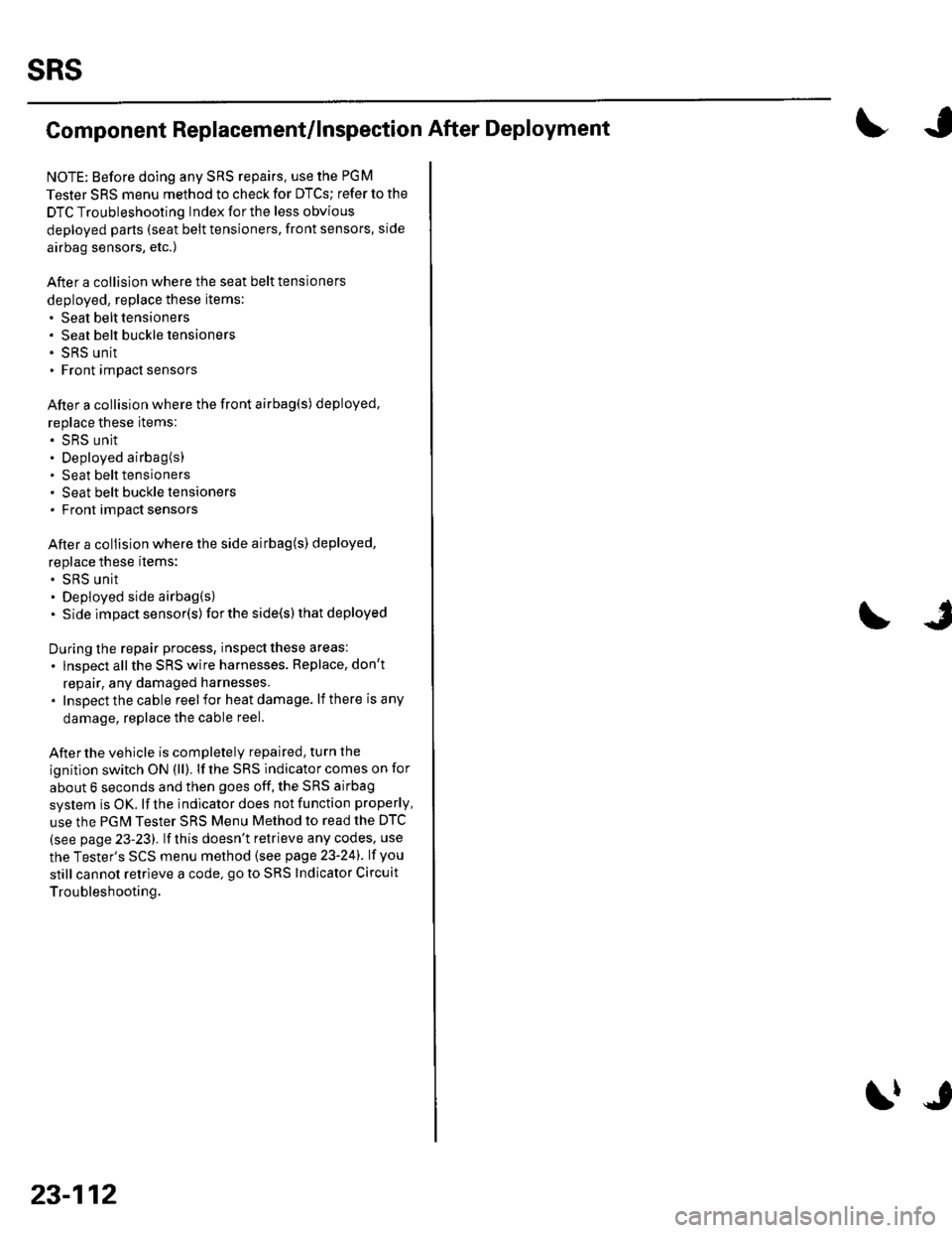
Component Replacement/lnspection After Deployment
NOTE: Before doing any SRS repairs. use the PGM
Tester SRS menu method to check for DTCS; refer to the
DTC Troubleshooting Index for the less obvious
deployed parts (seat beit tensioners, front sensors, side
airbag sensors, etc.)
After a collision where the seat belt tensioners
deployed, replace these items:' Seat belt tensioners. Seat belt buckle tensioners. SRS unit. Front impact sensors
After a collision where the front airbag(s) deployed.
replace these items:. SRS unit. Deployed airbag(s). Seat belt tensioners. Seat belt buckle tensioners. Front impact sensors
After a collision where the side airbag{s) deployed,
replace these items:. SRS unit. Deployed side airbag(s). Side impact senso(s)for the side(s) that deployed
During the repair process, inspect these areas:
. lnspect allthe SRS wire harnesses. Replace, don't
repair, any damaged harnesses.. Inspectthecable reelfor heatdamage. lf there is any
damage, replace the cable reel.
Afterthe vehicle is completely repaired, turn the
ignition switch ON (ll). lf the SRS indicator comes on for
about 6 seconds and then goes off, the SRS airbag
system is OK. lf the indicator does not function properly,
use the PGM Tester SRS Menu Method to read the DTC
(see page 23-23). lf this doesn't retrieve any codes, use
the Tester's SCS menu method (see page 23-24). lf you
still cannot retrieve a code, go to SRS Indicator Circuit
Troubleshooting.
23-112
\|J
Page 1133 of 1139
Service Manual lndex
)s
NOTE: Referto the lollowing listto look up A/C Pressure Switch CircuitDTCS, symptoms, fuses, connectors, wire Troubleshooting ......... ...-.-....-...-.-.-....-..21-32 Bharnesses, specifications, maintenanceschedules, and general serviceinlormation:
DTC Troubleshooting Indexes
A/C Signal CircuitTroubleshooting.........................-...... 11-'133 Back-up Light SwitchTest .......................................................... 13'3A/F lAir Fuel Ratiol SensorABS/TCS Components ........................ 19-34 Replacement ....................................... 1 1-113 Back-up Li9ht3EPS Components ................................. '17-22 Circuit DiagramFueland Emissions11-i A-Dillar Corner Trim
ABS Indicator Circuit
Heating/Ventilation ................................ 21-9 Replacement ...............-.....-..............-.... 20,96 Ball Joint BootssRS ........................................................ 23-28Replacement ......
... 19-52 Ball Joints
22-75
18 16
Remova1.............-.......... . ...........18-10Symptom Troubleshooting Indexes TroubleshootingABS/TCSComponents........................ 19 35Cruise Control System ..........................4 38 ABS Modulator-contml UnitEPS Components ................................. 17-23 Bemoval/lnstallation ............................ 19-57 BettervFan Controls10,12
Accessory Powor Socket Front
Blowor Pow€r Transistor
.......22 50
Blower UnitRemoval/lnstallation ............................ 21-39
Fuel and Em issions .............................. 11-10 ABS/TCS ComoonentsHeating/Ventilation..............................21 10 Component Location Index ................. 19-30 Beverage Holder
SRS ........................................................ 23'30 CircuitDiaqram.......................... 19'42Blower MotorReplacement .....21 41
21-38
Power 0istribution ...............................22-46 TesVReplacement .............................. 22'149Under-dash Fuse/Relay Box ............... 22 45Under-hood Fuse/Belay Box ...............22 44 Accessory Power Sockets
Fuse/Relay lndexes
(to harness)
Connector and Wire Harness lndexesComponent Connectors
Circuit Oiagram .................................. 22-149
Air Cleaner......2214 Rep1acemen1.....................................11-162
Air MixControl MotorMeintenence section .................... Section 3 Replacement ......................................... 21'34 Brake CelipersTest......................21-34 Overhaul19-14,23Gene.al lnlormation section........ Section 1
21.57
Airbag. Driver's
Ahernator FR Signal CircuitTroubleshooting .... .........-..........11 134
AntennaReplacement
Inspection ............................................. 19-24Rep|acement................. .................... 19-25
Bieke Meder Cylinder
Irake Discs
A
Replacement ....................................... 23 1 'l3 Inspection .................... ................... 19-13,22Repair ...........-...................................... 23 1 16Brake Fluid Level SwitchAirbag. Front Passenger's TestBeplacement....................................... 23-1 14AIC Brake LightsComponent Location fndex ...................21-3 Altemator CircuitDiagram....................................22-74Description.....................................-....21'1'l Beplacement ................ ........................... 4 29CircuitDiagram....................................21-14 Overhaul .................................................4-30 Brake Lines and Hoses
19.10
A/C CompressolReplacement .......-...-............................. 21 -41
A/C Compr€ssor ClulchRep1acement......................................... 19-15.........22-103 Inspection ............................................. 19-16Inspecton........Overhaul ..........
A/C CondenserReplacement,.,
21-442l-49 Audio Unit
Replacement
Brake PadsRemoval/lnstallation .. ........................22-100 Inspection/Rep1acement................ 19-11,20A/C Compressor Clutch CircuitTroubleshooting ................................... 21-30 Audio Unit Connector Brake Pedal22101 Adjustment..............19,6ArfC Comoressor Relief ValvcReplacement ..........-...-.......................... 21-51 Audio/Entertainment
A/C Compr$sor Thermal Protector Circuit DiagramReplacement............-............................ 21-51
Component Location In dex .................22-9A Test .......-.............. 22-84Breke Pedal Posilion Switch
Brake Pedal Position Switch Signal Clrcuit11-137
.....21 52
A/C Condenser Fan CircuitTroubleshooting ................... . . . . . .....21-28
)s
Troubleshooting
(cont'd)