engine HONDA CIVIC 2002 7.G Workshop Manual
[x] Cancel search | Manufacturer: HONDA, Model Year: 2002, Model line: CIVIC, Model: HONDA CIVIC 2002 7.GPages: 1139, PDF Size: 28.19 MB
Page 558 of 1139
EPS Control Unit Removal/
Installation
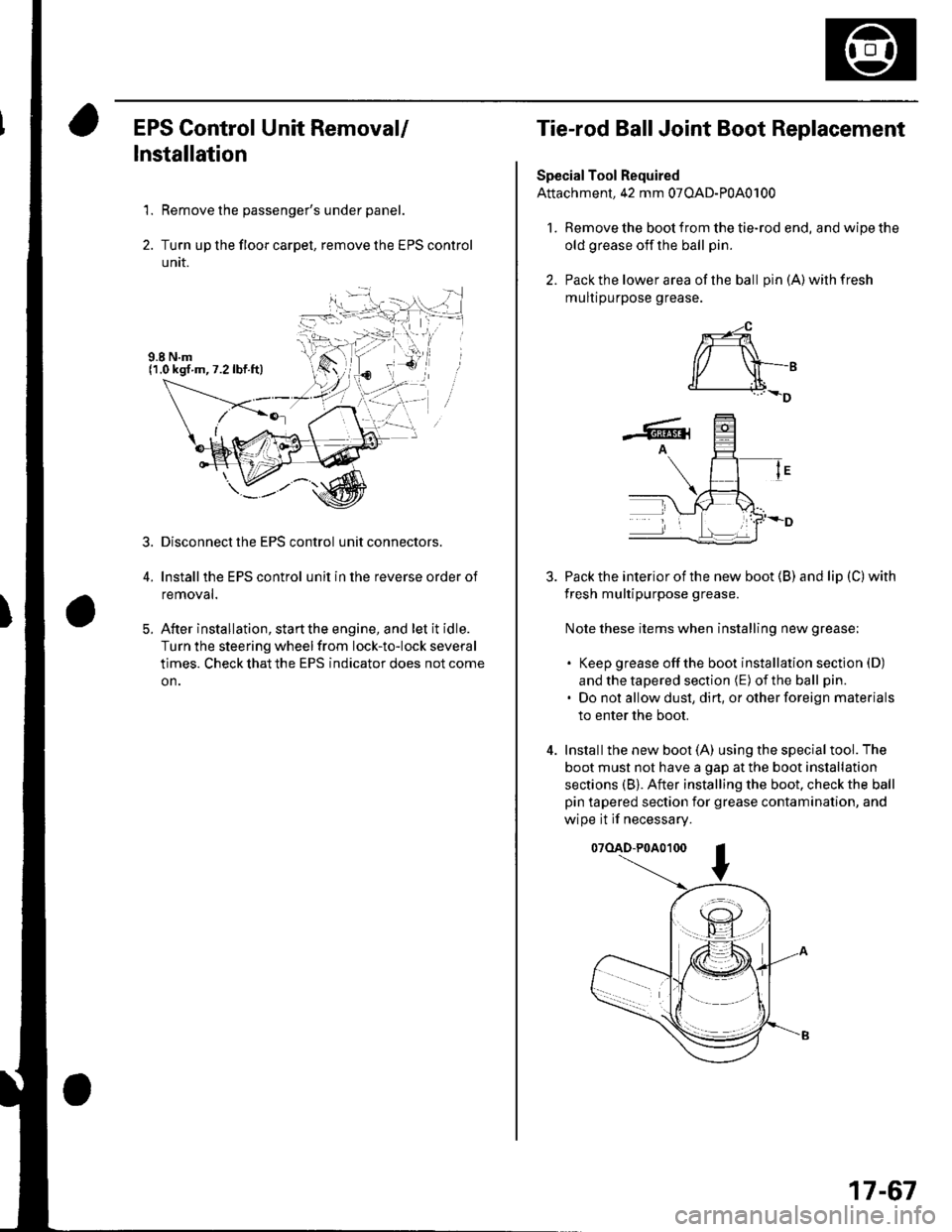
1. Remove the passenger's under panel.
2. Turn up the floor carpel, remove lhe EPS control
untr.
Disconnect the EPS control unit connectors.
lnstallthe EPS control unit in the reverse order of
removal.
After installation, start the engine, and let it idle.
Turn the steering wheelfrom lock-to-lock several
times. Check that the EPS indicator does not come
on.
3.
E
Tie-rod Ball Joint Boot Replacement
Special Tool Required
Attachment, 42 mm 07OAD-P0A0100
l. Remove the boot from the tie-rod end, and wipe the
old grease off the ball pin.
2. Pack the lower area of the ball pin(A)wilhfresh
mulr purpose grease.
3. Pack the interior of the new boot (B) and lip (C) with
fresh multipurpose grease.
Note these items when installing new grease;
. Keep grease offthe boot installation section (D)
and the tapered section (E) of the ball pin.
. Do not allow dust, dirt, or other foreign materials
to enter the boot.
4. Installthe new boot (A) using the specialtool. The
boot must not have a gap at the boot installation
sections (B). After installing the boot. check the ball
pin tapered section for grease contamination, and
wipe it if necessary.
07(lAD-P0A0100
*-4
r/ \-,d______i.l+_D
-6rA
17-67
Page 569 of 1139
Front Suspension
Knuckle/Hub/Wheel Bearing Replacement
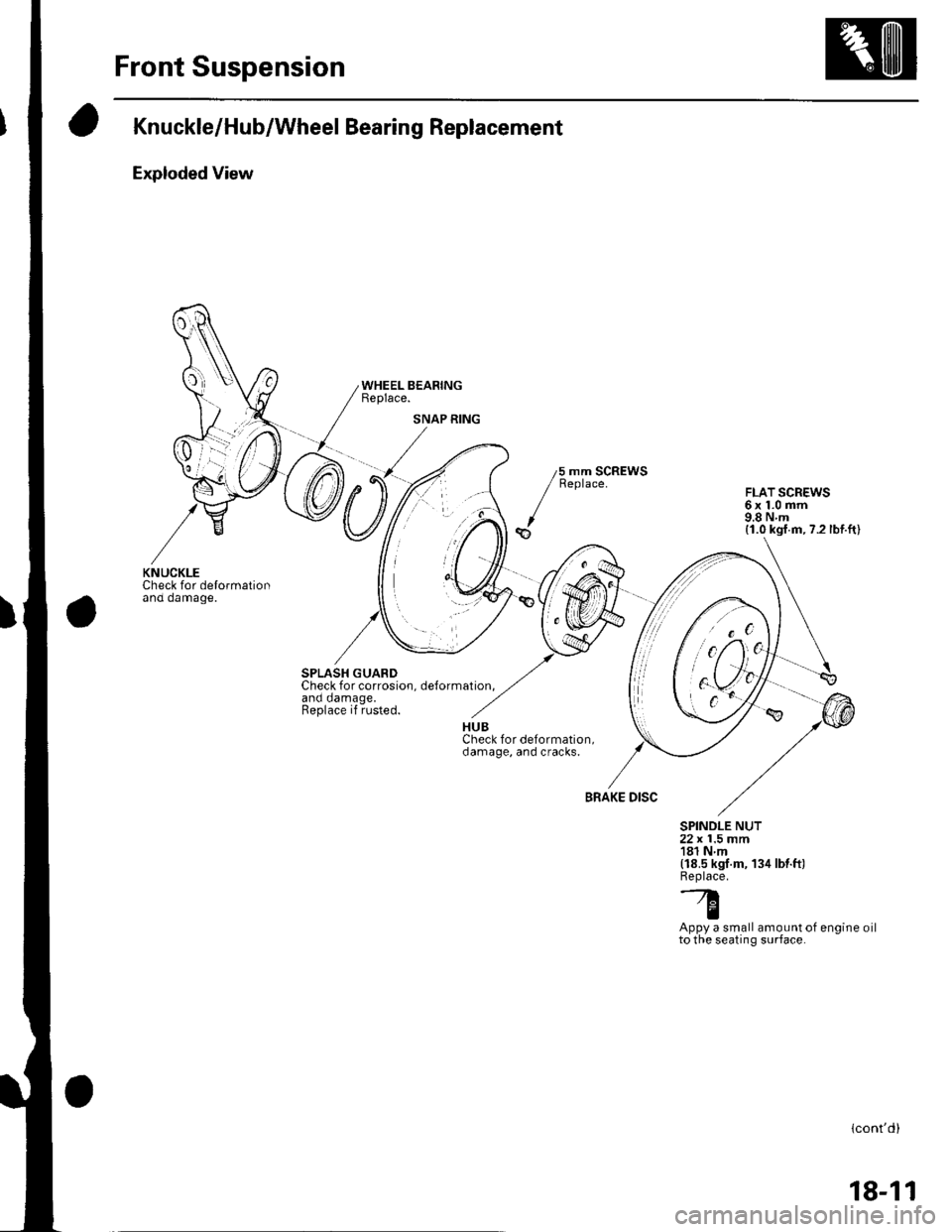
Exploded View
Check for delormationano oamage.
SPLASH GUARDCheck for corrosion. delormation.and damage.Replace if rusted.
WHEEL BEARINGReplace.
5 mm SCREWSReplace.FLAT SCREWS6x1.0mm9.8Nm(1.0 kgf.m,7.2 lbf.ft)
BRAKE DISC
SPINDLE NUT22 x 1.5 mm181 Nm(18.5 kgf.m, 134 lbt.ft)Replace.'--7.l'tq
IAppy a small amount of engine oilto the seating surface.
lcont'd)
SNAP RING
KNUCKLE
18-11
Page 573 of 1139
18.
19.
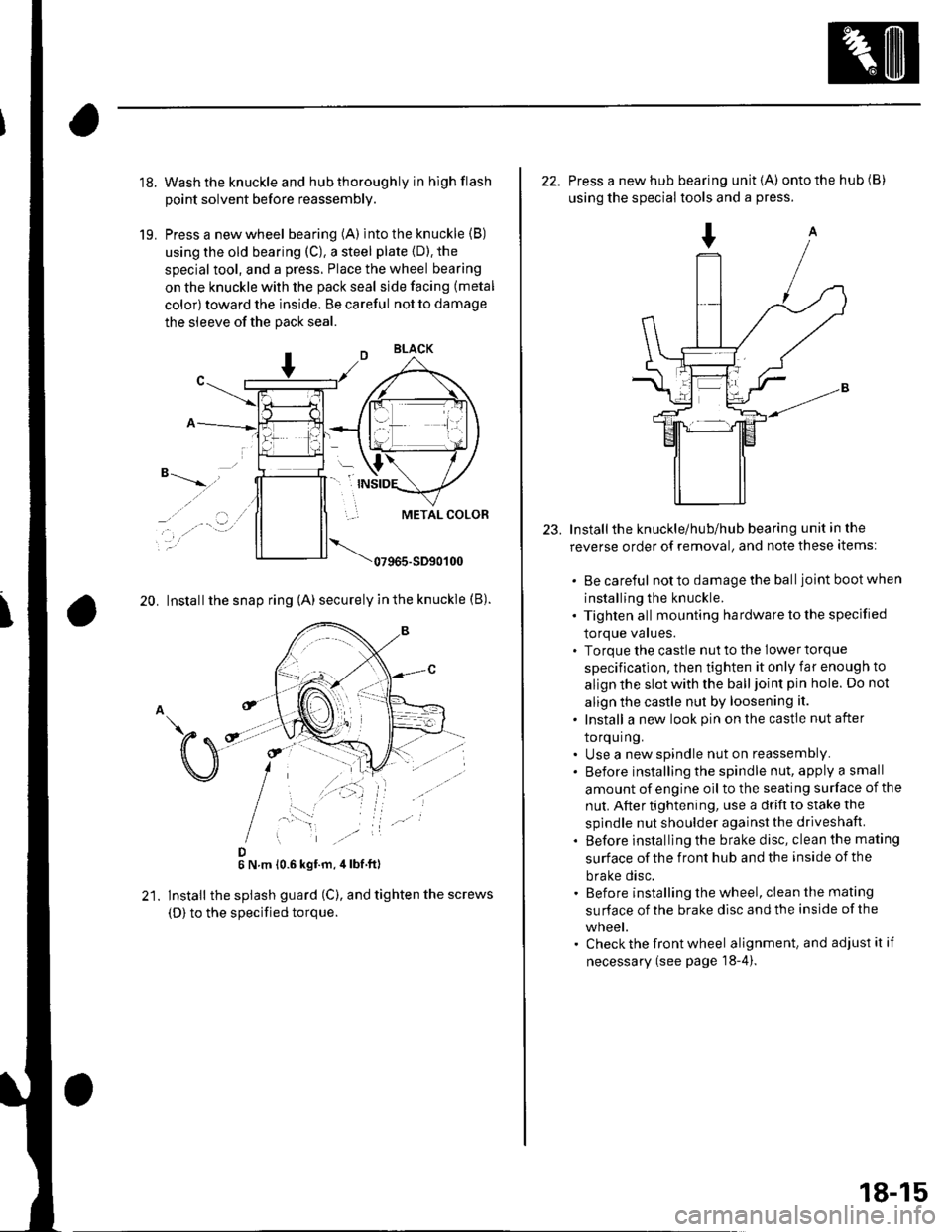
Wash the knuckle and hub thoroughly in hlgh flash
point solvent before reassembly.
Press a new wheel bearing (A) into the knuckle (B)
using the old bearing (C), a steel plate {D). the
special tool, and a press. Place the wheel bearing
on the knuckle with the pack seal side facing (metal
color) toward the inside. Be careful not to damage
the sleeve of the pack seal.
"-t-_"*,,''
_, .' . . a-�.) ../
..-.
20. Install the snap ring (A) securely in the knuckle (B).
D6 N.m 10.6 kgf.m,4lbf ft)
lnstall the splash guard (C), and tighten the screws
(D) to the specified torque.
23.
22. Press a new hub bearing unit {A) ontothehub(B)
using the special tools and a press.
Installthe knuckle/hub/hub bearing unit in the
reverse order of removal, and note these items:
. Be careful notto damagethe balljoint bootwhen
installing the knuckle.. Tighten all mounting hardware to the specified
lOrque values.. Torque the castle nut to the lower torque
specification, then tighten it only far enough to
align the slot with the ball joint pin hole. Do not
align the castle nut by loosening it.
. Install a new look pin on the castle nut after
torquing.. Use a new spindle nut on reassembly.. Before installing the spindle nut, apply a small
amount of engine oil to the seating surface of the
nut. After tightening, use a drift to stake the
spindle nut shoulder against the driveshaft.
. Before installlng the brake disc, clean the mating
surface of the front hub and the inside of the
brake disc.. Before installing the wheel, clean the mating
su rface of the brake disc and the inside of the
wneet.. Check the front wheel alignment, and adjust it if
necessary (see page 18-4).
18-15
Page 584 of 1139
Rear Suspension
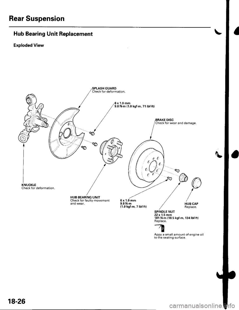
Hub Bearing Unit Replacement
Exploded View
Check for delormation.
SPLASH GUARDCheck for deformation.
x 1.0 mm9.8 N.m (1.0 kgf.m, ?1 lbf ftl
HUB BEARING UNITCheck for faulty movementand wear.6x1.0mm9,8 N.m{1.0 kgf.m, 7 lbf.ft}
un
Y
HUB CAPReplace.
SPINDLE NUT22 x 1.5 mm181 N.m {18.5 kgt.m, 134lbf.ft}Beplace.-A
TAppy a small amount oI engine oilto the seating surface.
Check for wear and damage.
,, o0'[',/-\'
KNUCKLE
18-26
Page 587 of 1139
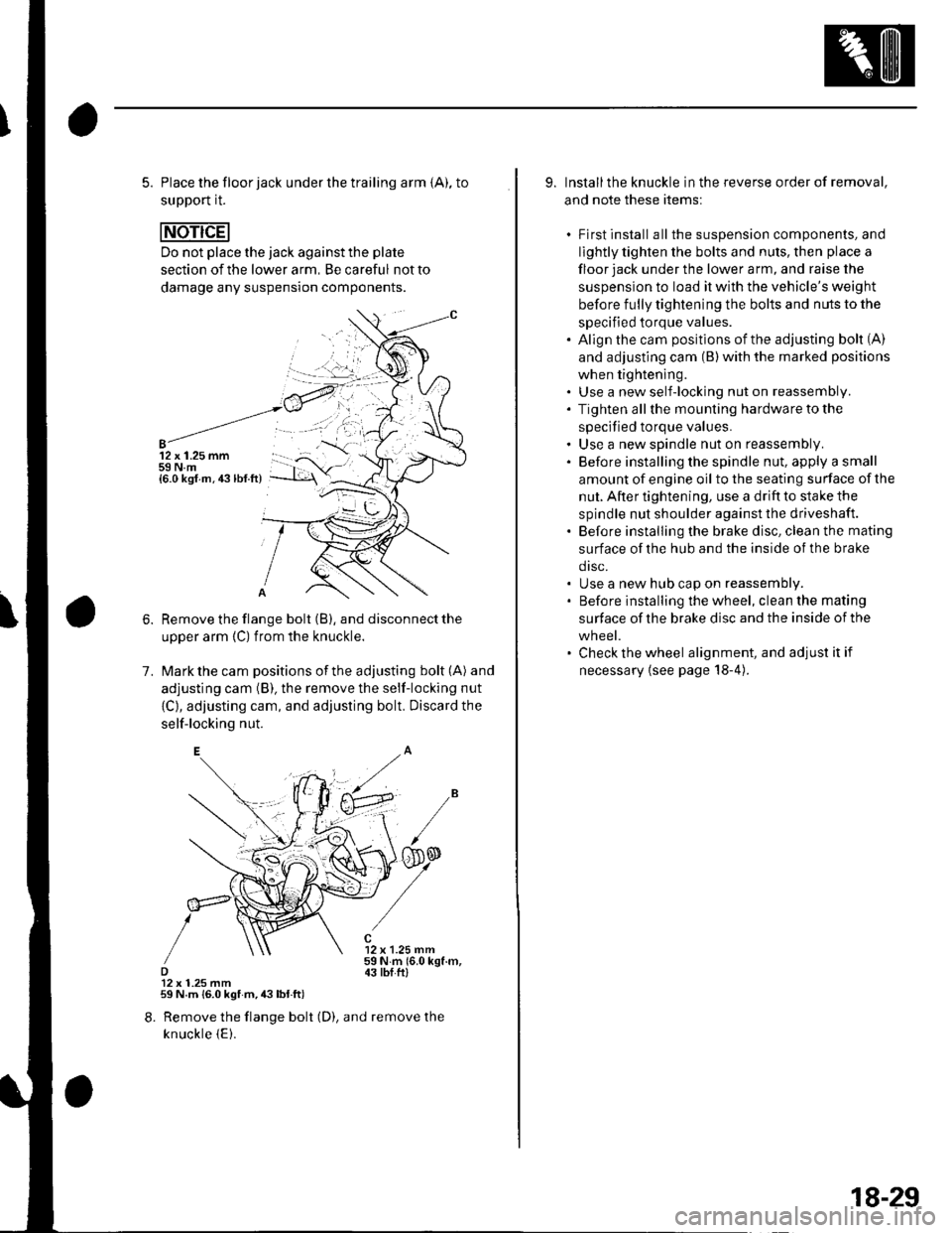
5. Place the floor jack under the trailing arm {A), to
support it.
Do not place the jack against the plate
section of the lower arm, Be careful not to
damage any suspension components.
12 x 1.25 mm59 N.m{6.0 ksf.m.43lbf.ft)
1.
Remove the flange bolt (B), and disconnect the
upper arm {C) from the knuckle.
Mark the cam positions of the adjusting bolt (A) and
adjusting cam (B), the remove the self-locking nut
{C}, adjusting cam, and adjusting bolt. Discard the
self-locking nut.
12 x 1.25 mm59Nm(6.0kgf.m,43 tbI.ftl12 x 1.25 mm59 N.m {6.0 kgf m,43lbl.ft)
8. Remove the flange bolt (D), and remove the
knuckle {E).
9. Installthe knuckle in the reverse order of removal,
and note these items:
. First install all the suspension components, and
lightly tighten the bolts and nuls, then place a
floor jack under the lower a rm, and raise the
suspension to load it with the vehicle's weight
before fully tightening the bolts and nuts to the
specified torque values.. Align the cam positions of the adjusting bolt (A)
and adjusting cam (B) with the marked positions
when tightening.. Use a new self-locking nut on reassembly.. Tighten allthe mounting hardware to the
specified torque values.. Use a new spindle nut on reassembly.. Before installing the spindle nut, apply a small
amount of engine oil to the seating surface of the
nut. After tightening, use a drift to stake the
spindle nut shoulder against the driveshaft.. Before installing the brake disc, clean the mating
surface of the hub and the inside of the brake
drsc.. Use a new hub cap on reassembly.. Before installing the wheel, clean the mating
surface of the brake disc and the inside of the
wheel.. Check the wheel alignment, and adjust it if
necessary {see page 18-4).
18-29
Page 599 of 1139
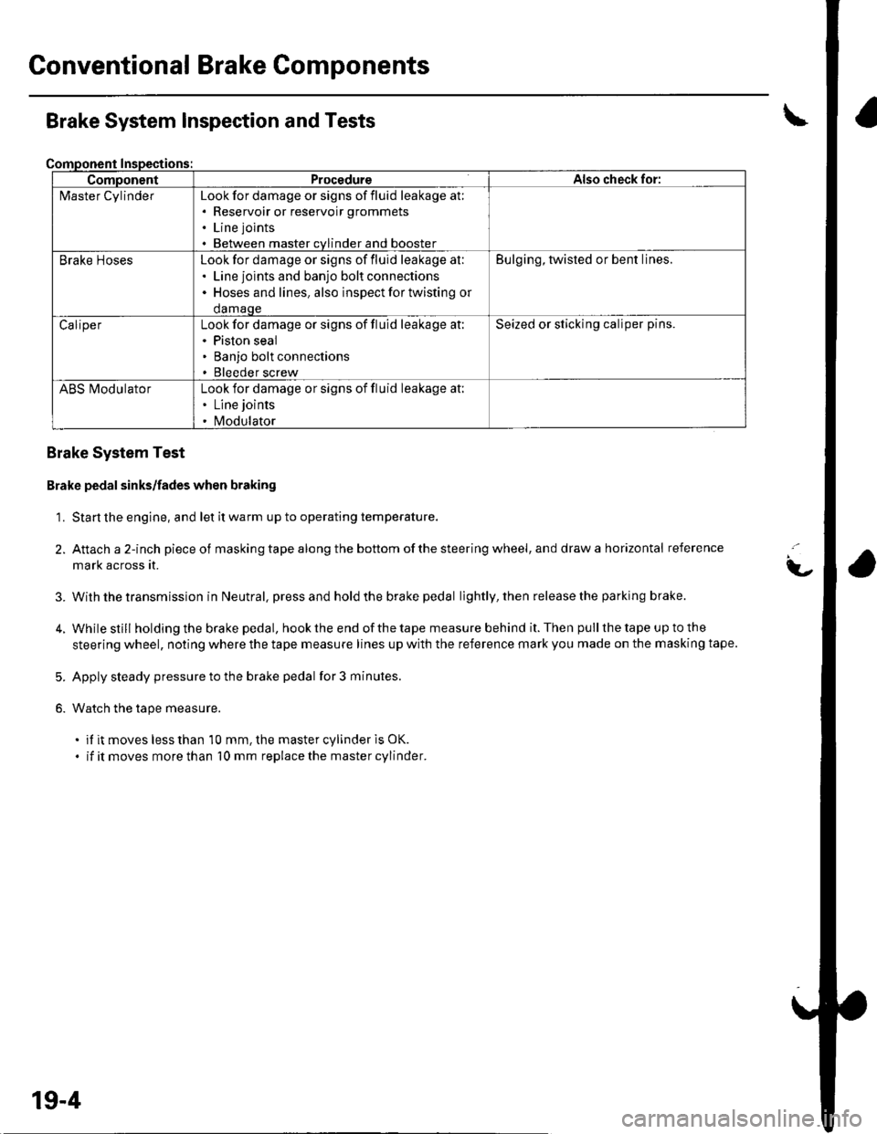
Gonventional Brake Components
ComponentProcedureAlso check for:
l\4aster CylinderLook for damage or signs of fluid leakage at;. Reservoir or reservoir grommets
. Line joints
. Between master cvlinder and booster
Brake HosesLook for damage or signs of fluid leakage at:. Line joints and banjo bolt connections. Hoses and lines. also inspect for twisting or
damaqe
Bulging, twisted or bent lines.
CaliperLook for damage or signs of fluid leakage at:. Piston seal. Banjo bolt connections. Bleeder screw
Seized or sticking caliper pins.
ABS l\ilodulatorLook for damage or signs of fluid leakage at:. Line joints
. Modulator
Brake System Inspection and Tests
Brake System Test
Brake pedal sinks/fades when braking
1. Start the engine, and let it warm up to operating temperature.
2. Attach a 2-inch pieceof masking tape along the bottom of the steering wheel, and draw a horizontal reference
mark across it.
With the transmission in Neutral, press and hold the brake pedal lightly, then release the parking brake.
While still holding the brake pedal, hook the end of the tape measure behind it. Then pull the tape up to the
steering wheel, noting where the tape measure lines up with the reference mark you made on the masking tape.
Apply steady pressure to the brake pedal for 3 minutes.
Watch the tape measure.
. if it moves less than 10 mm, the master cylinder is OK.
. if it moves more than 10 mm replace the master cylinder.
t-
3.
5.
6.
19-4
Page 600 of 1139
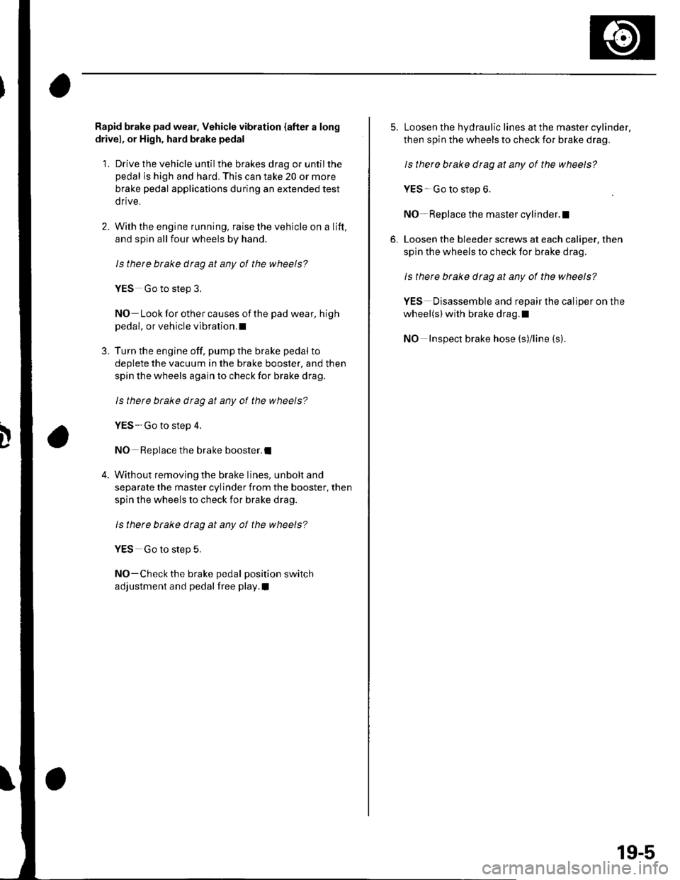
Rapid brake pad wear. Vehicle vibration {after a long
drivel, or High, hard brake pedal
1. Drive the vehicle until the brakes drag or untilthe
pedal is high and hard. This can take 20 or more
brake pedal applications during an extended test
drive.
2. With the engine running, raise the vehicle on a lift,
and spin all four wheels by hand.
ls there btake drag at any of the wheels?
YES Go to step 3.
NO Look for other causes of the pad wear, high
pedal, or vehicle vibration.I
3. Turn the engine off, pump the brake pedal to
deplete the vacuum in the brake booster, and then
spin the wheels again to check for brake drag.
ls therc brake dtag at any ot the wheels?
YES-Go to step 4.
NO Replace the brake booster.I
4. Without removing the brake lines, unbolt and
separate the master cylinder from the booster, then
spin the wheels lo check for brake drag.
ls there btake drag at any of the wheels?
YES Go to step 5,
NO-Check the brake pedal position switch
adjustment and pedal free play.I
5. Loosen the hydraulic lines at the master cylinder,
then spin the wheels to check for brake drag.
ls there brake drag at any of the wheels?
YES Go to step 6.
NO- Replace the master cylinder.l
6. Loosen the bleeder screws at each caliper, then
spin the wheels to check for brake drag.
Is there brake drag at any of the wheels?
YES Disassemble and repair the caliper on the
wheel(s) with brake drag.l
NO Inspect brake hose (s)/line (s).
19-5
Page 601 of 1139
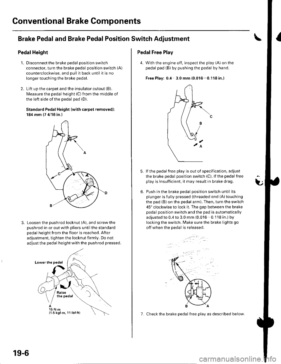
Conventional Brake Components
Brake Pedaland Brake PedalPosition Switch Adjustment
Pedal Height
1.Disconnect the brake pedal position switch
connector, turn the brake pedal position switch (A)
counterclockwise, and pull it back until it is no
longer touching the brake pedal.
Lift up the carpet and the insulator cutout (B).
l\4easure the pedal height (C) from the middle of
the left side of the pedal pad (D).
Standard Pedal Height (with carpet removed):
184 mm (7 4/16 in.)
Loosen the pushrod locknut (A), and screw the
pushrod in or out with pliers until the standard
pedal height from the floor is reached. After
adjustment, tighten the locknut firmly. Do not
adjust the pedal height with the pushrod pressed.
15 N.m(1.5 kgl m. 11 lbl ft)
19-6
7. Check the brake pedal free play as described below.
Pedal Free Play
4. With the engine off, inspect the play (A) on the
pedal pad (B) by pushing the pedal by hand.
Free Play: 0.4- 3.0 mm {0.016 0.'l18in.)
lf the pedal free play is out of specification, adjust
the brake pedal position switch (C). lf the pedal free
play is insufficient, it may result in brake drag.
Push in the brake oedal oosition switch until its
plunger is fully pressed (threaded end (A)touching
the pad (B) on the pedal arm). Then, turn the switch
45" clockwise to lock it. The gap between the brake
pedal position switch and the pad is automatically
adjusted to 0.4 to 3.0 mm (0.016 0.118 in.) by
locking the switch. Make sure the brake lights go
otf when the pedal is released.
t
6.
Page 602 of 1139
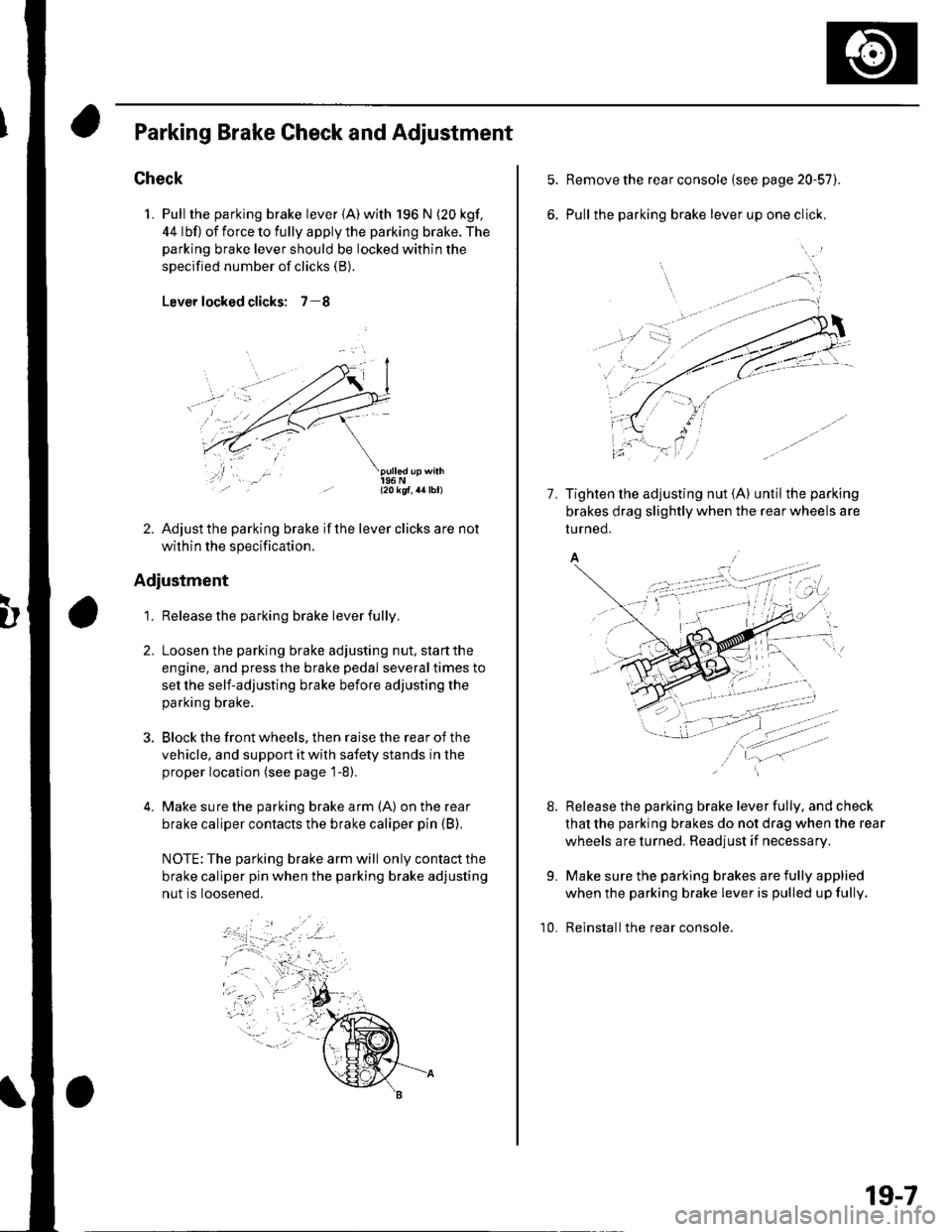
Parking Brake Check and Adiustment
Check
1. Pull the parking brake lever {A) with 196 N (20 kgf,
44 lbf) of force to fully apply the parking brake. The
parking brake lever should be locked within the
specified number of clicks (B).
Lever locked clicks: 7-8
- l2okqf, a4lbl)
2. Adjust the parking brake if the lever clicks are not
within the specification.
Adjustment
1. Release the parking brake lever fully.
Loosen the parking brake adjusting nut, start the
engine, and press the brake pedal several times to
set the self-adjusting brake before adjusting the
parking brake.
Block the front wheels, then raise the rear of the
vehicle, and support it with safety stands in the
proper location (see page 1-8).
Make sure the parking brake arm (A) on the rear
brake caliper contacts the brake caliper pin (B),
NOTE: The parking brake arm will only contact the
brake caliper pin when the parking brake adjusting
nut is loosened.
Remove the rear console {see page 20-57).
Pull the parking brake lever up one click,
7, Tighten the adjusting nut {A} until the parking
brakes drag slightly when the rear wheels are
tu rned.
A/
Release the parking brake lever fully, and check
that the parking brakes do not drag when the rear
wheels are turned. Readjust if necessary.
Make sure the parking brakes are fully applied
when the parking brake lever is pulled up fully.
Reinstall the rear console.
8.
9.
10.
19-7
Page 610 of 1139
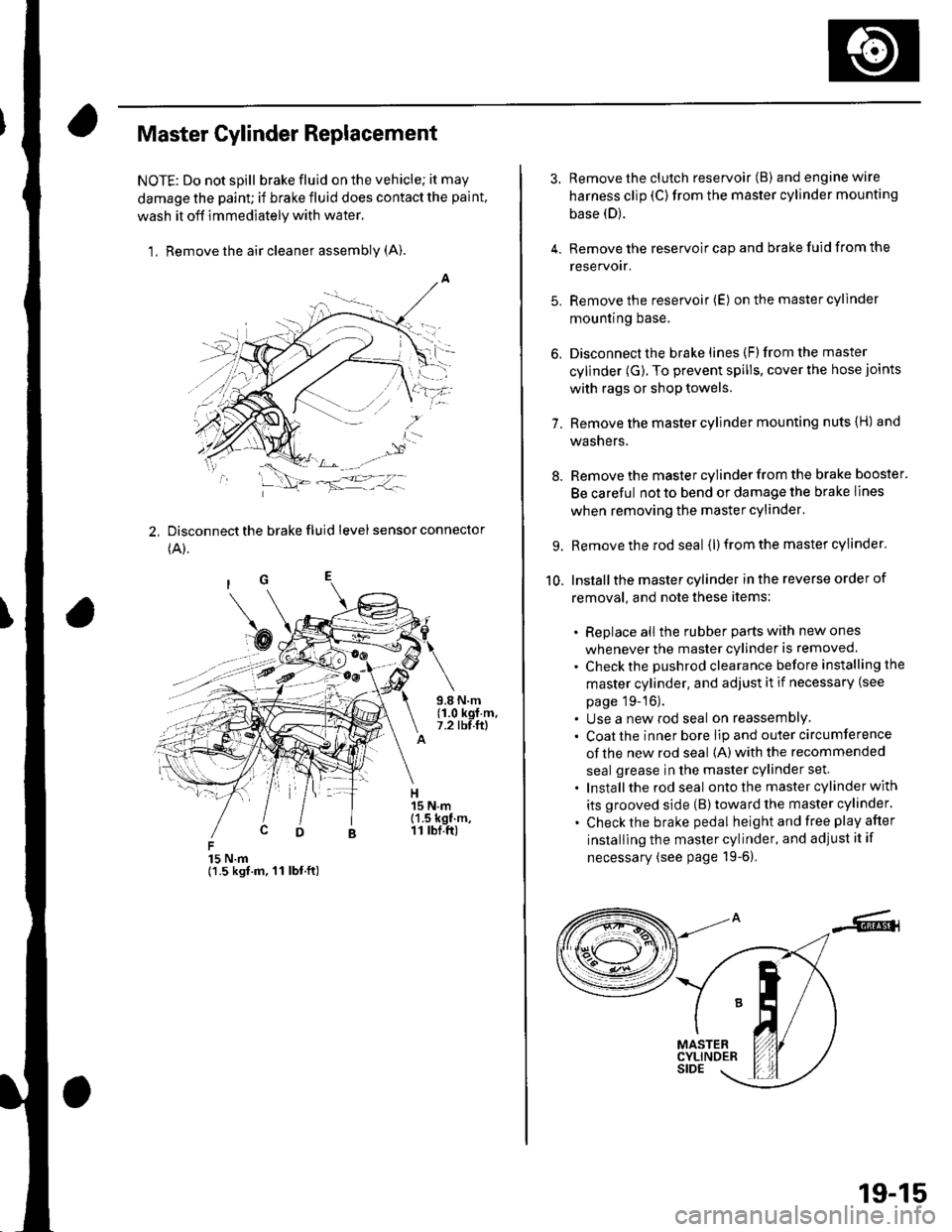
Master Cylinder Replacement
NOTE: Do not spill brake fluid on the vehicle; it may
damage the paint; if brake fluid does contact the paint,
wash it off immediately with water,
1, Remove the air cleaner assembly (A).
2, Disconnect the brake fluid level sensor connector
(A).
15 N.m{1.5 kgt.m, 11 lbt.ft)
3. Remove the clutch reservoir (B) andenginewire
harness clip (C)from the master cylinder mounting
base (D).
4. Remove the reservoir cap and brake fuid from the
reservoir.
5. Remove the reservoir (E) on the master cylinder
mountrng Dase.
6, Disconnect the brake lines (F)from the master
cylinder (G). To prevent spills, cover the hose joints
with rags or shop towels.
7. Remove the master cylinder mounting nuts {H) and
washers.
8. Remove the master cylinder from the brake booster.
Be careful not to bend or damage the brake lines
when removing the master cylinder.
9. Remove the rod seal (l) from the master cylinder.
10. Installthe master cylinder in the reverse order of
removal, and note these items:
. Replace all the rubber parts with new ones
whenever the master cylinder is removed.
. Check the pushrod clearance before installing the
master cylinder. and adjust it if necessary (see
page 19-16).. Use a new rod seal on reassemblY. Coat the inner bore lip and outer circumference
of the new rod seal {A) with the recommended
seal grease in the master cylinder set.
. Installthe rod seal ontothe master cylinder with
its grooved side (B)toward the master cylinder.
. Check the brake pedal height and free play after
installing the master cylinder, and adjust it if
necessary (see page 19-6).
19-15