engine HONDA CIVIC 2002 7.G Workshop Manual
[x] Cancel search | Manufacturer: HONDA, Model Year: 2002, Model line: CIVIC, Model: HONDA CIVIC 2002 7.GPages: 1139, PDF Size: 28.19 MB
Page 779 of 1139
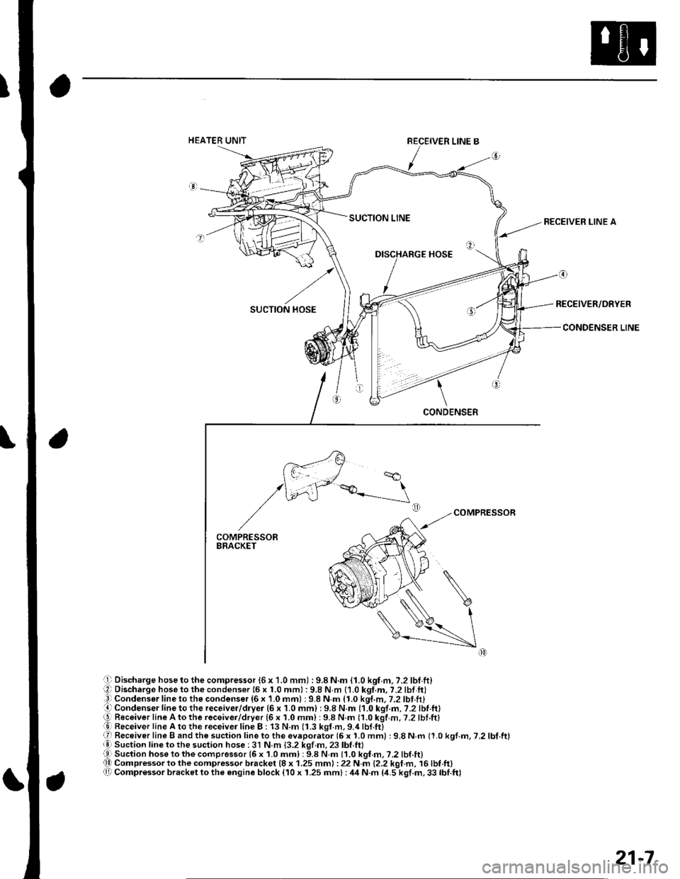
Discharge hose to the compressor {6 x 1.0 mm) : 9.8 N.m {1.0 kgf.m, 7.2 lbl.ft}Discharge hose to the condenser (5 x 1.0 mml : 9.8 N.m {1.0 kgt.m, 7.2 lbf ft)Condenser line to the condenser (6 x 1.0 mm) : 9.8 N.m {1.0 kgf,m, 7.2 lbt.ft}Condenser f ine to the receiver/dryer {6 x 1.0 mm} : 9.8 N.m (1.0 kgt.fi,7.2lbt.ltlReceiver lineAtothe receiver/dryer {6 x 1.0 mm} : 9.8 N.m {1.0 kgf .m. 7.2 lbf .ft}Receiver line A to the receivei line B : 13 N.m (1.3 kgr.m, 9.4 lbf.ft)Receiver line B and the suction line to the evaporator (6 x 1.0 mm) :9.8 N.m 11.0 kgf.m, 7,2 lbf.ft)Suction line to the suction hose : 3l N m {3.2 kgf.m, 23 lbf ftlSuction hose 1o the compressor (6 x 1.0 mm) : 9.8 N.m 11.0 kgf.m. ?.2 lbf.lt)Compressor to the compressor b.acket {8 x 1.25 mm) : 22 N m {2.2 kgt.m, 16 lbf.ft)Compr€ssor bracket to the engine block {10 x 1.25 mm} : ,14 N.m 14.5 kgf.m, 33 lbf.ft)
RECEIVER LINE A
RECEIVER/DRYER
CONDENSER LINE
21-7
Page 801 of 1139
Heating and Air Conditioning
Radiator and Condenser Fans
Common
(cont'dl
Circuit Troubleshooting
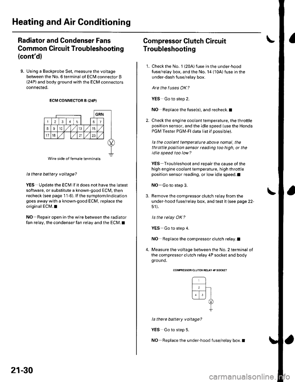
9. Using a Backprobe Set, measure the voltage
between the No. 6 terminal of ECN4 connector B
{24P) and body ground with the ECM connectors
connecteo.
ECM CONNECTOR B {24P}
ls there battery voltage?
YES UDdate the ECM if it does not have the latest
so{tware, or substitute a known-good ECM, then
recheck (see page 11-6). lf the symptom/indication
goes away with a known-good ECM, replace the
original ECM.I
NO Repair open in the wire between the radiator
fan relay, the condenser fan relay and the ECM. t
Wire side of female terminals
21-30
Compressor Clutch Circuit
Troubleshooting
1. Check the No. 1 (20A) fuse in the under-hood
fuse/relay box, and the No. 14 {10A)fuse in the
under-dash fuse/relay box.
Are the tuses OK?
YES Go to step 2.
NO Replace the fuse(s), and recheck.I
2. Check the engine coolant temperature, the throttleposition sensor, and the idle speed (use the Honda
PGM Tester PGM-Fl data list if possible).
ls the coolant temperaturc above nomal, the
throttle position sensor rcading too high, or the
idle speed too low?
YES Troubleshoot and repair the cause of the
high engine coolant temperature, high throttle
position sensor reading, or low idle speed.l
NO-Go to step 3.
3. Remove the compressor clutch relay from the
under-hood fuse/relay box, and test it (see page 22-
51 ).
ls the relay OK?
YES Go to step 4.
NO Replace the compressor clutch relay.I
4. Measure the voltage between the No. 2 terminal of
the compressor clutch relay 4P socket and body
ground.
\
COMPfiESSON CLUTCH BELAY 'P SOCKET
ls there battery voltage?
YES Go to step 5.
NO Replace the under-hood fuse/relay box.I
Page 803 of 1139
Heating and Air Conditioning
Compressor Clutch Circuit
Troubleshooting (cont'dl
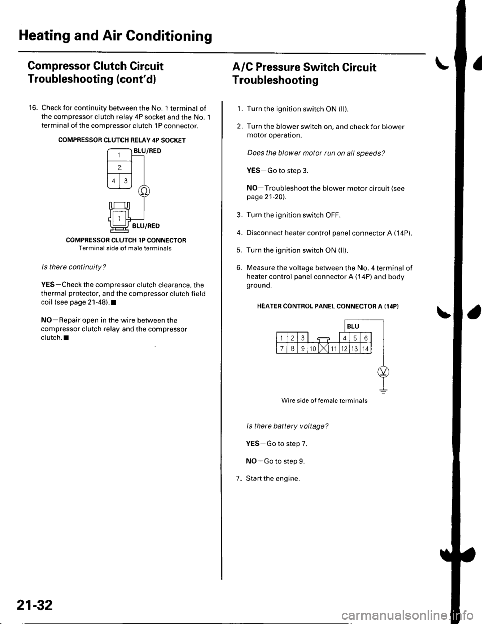
16. Check for continuity between the No. lterminal of
the compressor clutch relav 4P socket and the No. l
terminal of the compressor clutch 1P conneclor.
COMPRESSON CLUTCH RELAY 4P SOCKET
COMPRESSOR CLUTCH 1P CONNECTORTerminal side of male terminals
ls therc continuity?
YES-Check the compressor clutch clearance, the
thermal protector, and the compressor clutch field
coil (see page 21-48).I
NO-Repair open in the wire between the
compressor clutch relay and the compressor
clutch.l
21-32
A/C Pressure Switch Circuit
Troubleshooting
'1. Turn the ignition switch ON {ll).
2. Turn the blower switch on, and check for blower
motor operatron.
Does the blower motor run on all speeds?
YES Go to step 3.
NO Troubleshoot the blower motor circuit (see
page 21-20).
3. Turn the ignition switch OFF.
4. Disconnect heater control panel connectorA ('14P).
5. Turn the ignition switch ON (ll).
6. Measure the voltage between the No, 4 terminal of
heater control panel connector A {14P) and body
grou nd.
HEATER CONTROL PANEL CONNECTOR A (I4P}
1.
ls there battety voltage?
YES Go to step 7.
NO-Go to step 9.
Stan the engine.
Wire side of female termina's
Page 811 of 1139
Heating and Air Gonditioning
Blower Unit Removal and Installation {cont'd}
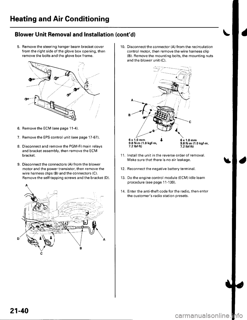
Remove the steering hanger beam bracket cover
from the right side of the glove box opening, then
remove the bolts and the olove box frame.
1.
8.
9.
Remove the ECM (see page 11-4).
Remove the EPS control unit (see page 17-67).
Disconnect and remove the PGM-Fl main relays
and bracket assembly, then remove the ECM
bracket.
Disconnect the connectors {A) from the blower
motor and the power transistor, then remove the
wire harness clips (B) and the connectors (C).
Remove the self-tapping screws and the bracket (D).
A
21-40
10. Disconnectthe connector {A) from the recirculation
control motor, then remove the wire harness clip
{B). Remove the mounting bolts, the mounting nuts
and the blower unit (C).
6x 1.0 mm I9.8 N.m (1.0 kgt.m,7.2 tbt.ftl
6x1.0mm9.8 N.m (1.0 kgf.m,?.2 tbf.ft)
11.
14.
Installlhe unit in the reverse order of removal.
Make sure that there is no air leakage.
Reconnect the negative battery terminal.
Do the engine control module (ECM) idle learn
procedure {see page 11-139).
Enter the anti-theft code for the radio, then enter
the customer's radio station presets.
\
'13.
Page 814 of 1139
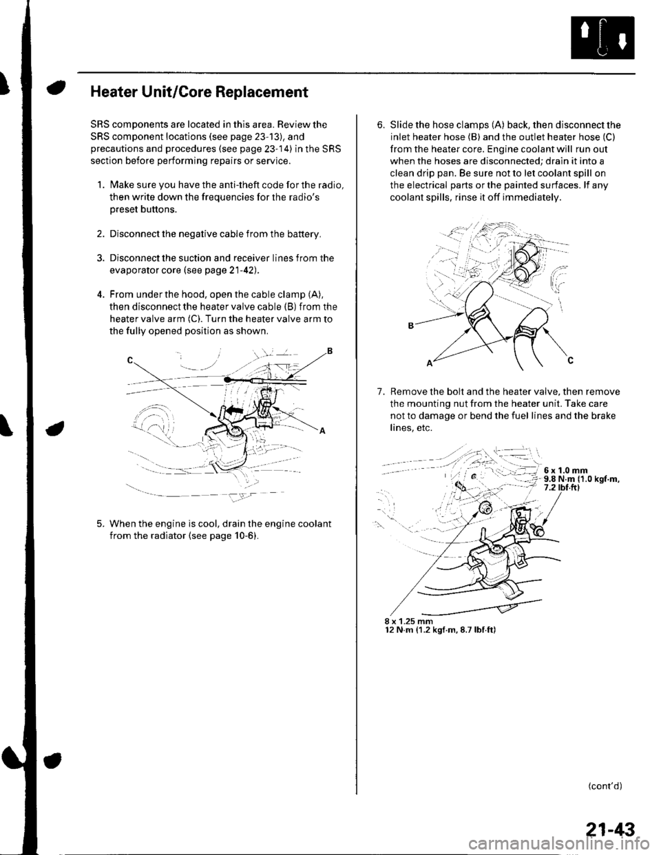
Heater Unit/Core Replacement
SRS components are located in this area. Review the
SRS component locations (see page 23'13), and
precautions and procedures (see page 23-14) in the SRS
section before performing repairs or service.
1. Make sure you have the anti-theft code forthe radio,
then write down the freouencies for the radio's
Dreset buttons.
4.
Disconnect the negative cable from the battery,
Disconnect the suction and receiver lines from the
evaporator core (see page 21-42).
From under the hood, open the cable clamp (A),
then disconnect the heater valve cable (B) from the
heater valve arm (C). Turn the heater valve arm to
the fully opened position as shown
When the engine is cool, drain the engine coolant
from the radiator (see page 10-6).
6. Slide the hose clamps (A) back, the n d isconnect the
inlet heater hose (B) and the outlet heater hose (C)
from the heater core. Engine coolant will run out
when the hoses are disconnected; drain it into a
clean drip pan. Be sure not to let coolant spill on
the electrical parts or the painted surfaces. lf any
coolant spills, rinse it off immediately.
Remove the bolt and the heater valve, then remove
the mounting nut from the heater unit. Take care
not to damage or bend the fuel lines and the brake
lines, etc.
7.
8 x 1.25 mm12 N.m (1.2 kgf.m,8.7lbf.ft)
(cont'd)
21-43
Page 816 of 1139
13. Installthe heater core and the evaporator core in
the reverse order of removal.
14. Installthe heater unit in the reverse order of
removal, and note these items:
. Do not interchange the inlet and outlet heater
hoses, and installthe hose clamps securely.. Refillthe cooling system with engine coolant (see
page 10-6).. Adjust the heater valve cable (see page 2'l-461.. Make sure that there is no coolant leakage.. Make sure that there is no air leakage.. Refer to evaporator core replacement {see step 6
on page 21-42).. Do the engine control module (ECl\4) idle learn
procedure (see page 11-139).. Enter the anti-theft code for the radio, then enter
the customer's radio station Dresets.
21-45
Page 818 of 1139
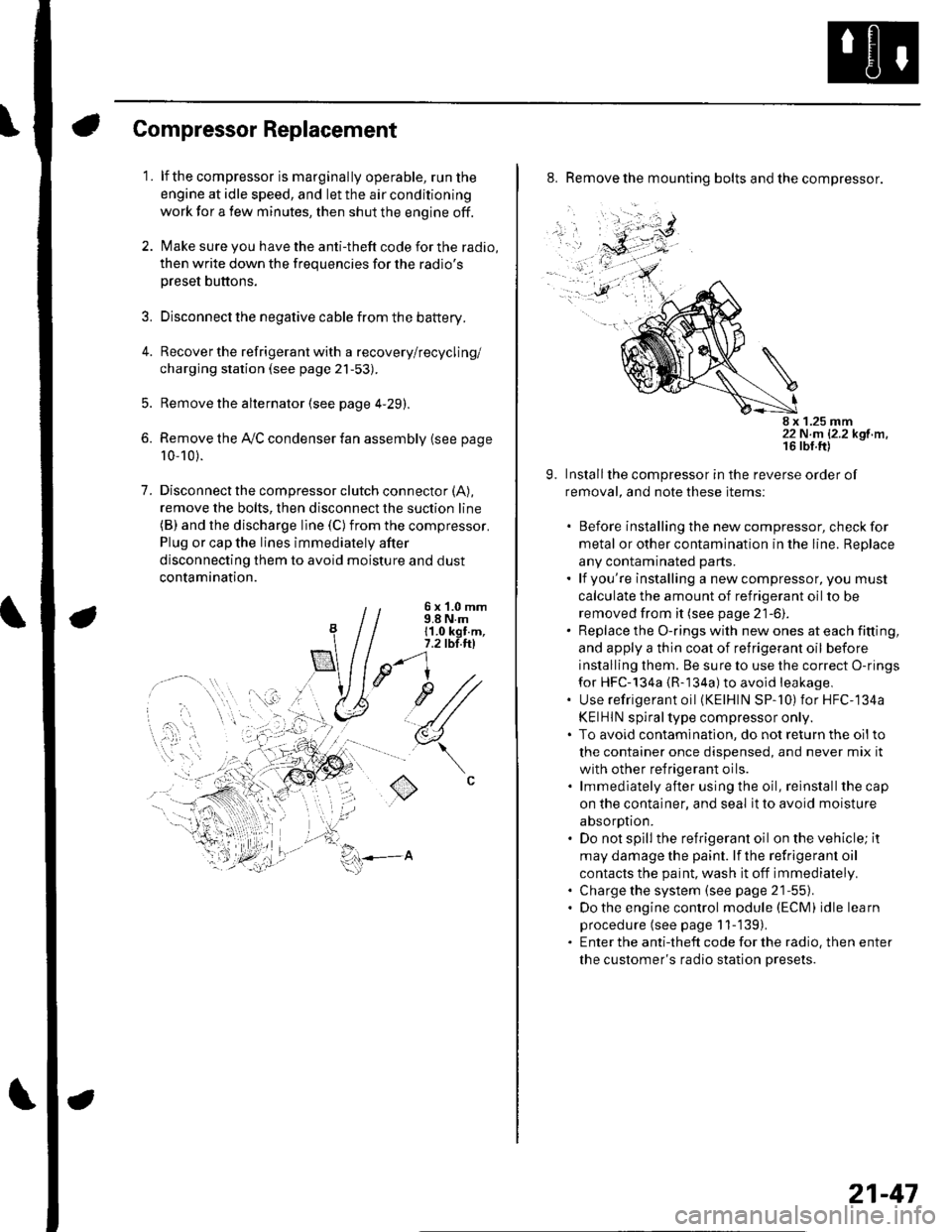
Compressor Replacement
1. lf the compressor is marginally operable, run the
engine at idle speed, and let the air conditioning
work for a few minutes, then shut the engine off.
2. Make sure you have the anti-theft code for the radio,
then write down the frequencies for the radio's
preset buttons.
3. Disconnect the negative cable from the battery.
4. Recover the refrigerant with a recovery/recycling/
charging station (see page 21-53).
5. Remove the alternator (see page 4-29).
6. Remove the Ay'C condenser fan assembly (see page
10-10).
7. Disconnectthe compressor clutch connector (A),
remove the bolts, then disconnect the suction line(B) and the discharge line (C)from the compressor.
Plug or cap the lines immediately after
disconnecting them to avoid moisture and dust
contamination.
6 x '1.0 mm9.8 N.m11.0 kgt.m,7.2 tbl.ttl
u1/
(
o
8. Remove the mounting bolts and the compressor.
8 x 1.25 mm22 N.m 12.2 kgf.m.
9. Installthe compressor in the reverse order of
removal, and note these items:
. Before installing the new compressor, check for
metal or other contamination in the line. Replace
any contaminated parts.. lf you're installing a newcompressor, you must
calculate the amount of refrigerant oil to be
removed from it (see page 21-6).. Replace the O-rings with new ones at each fitting,
and apply a thin coat of refrigerant oil before
installing them. Be sure to use the correct O-rings
for HFC-134a {R-134a) to avoid leakage,. Use refrigerant oil (KElHlN SP-'10) for HFC-134a
KEIHIN spiral type compressor only.. To avoid contaminatlon, do not return the oilto
the container once dispensed, and never mix it
with other refrigerant oils.. lmmediately after using the oil, reinstallthe cap
on the container, and seal it to avoid moisture
absorption.. Do not spill the refrigerant oil on the vehicle; it
may damage the paint. lf the refrlgerant oil
contacts the paint, wash it off immediately.. Charge the system (see page 21-55).. Do the engine control module (ECM) idle learn
procedure (see page 11-'139).. Enter the antitheft code for the radio, then enter
the customer's radio station presets.
21-47
Page 829 of 1139
Heating and Air Conditioning
A/C System Tests (cont'd)
1.
Performance Test
Air conditioning refrigerant or lubricant vapor
can irritate your eyes, nose, or throar.
Be carefulwhen connecting service equipment.
Do not breathe refrigerant or vapor.
The performance test will help determine if the air
conditioner system is operating within specifications.
Use only service equipment that is U.L.-listed and is
cenified to meet the requirements of SAE J2210 toremove HFC-134a (R-134alfrom the air conditioning
system.
lf accidental system discharge occurs, ventilate the
work area before resuming service
R-134a service equipment or vehicle air conditioning
systems should not be pressure tested or leak testedwith compressed air.
Additional health and safety information may be
obtained from the refrigerant and lubricant
manufacturers.
Connect a R-134a refrigerant recover/recycling/
charging station to the high-pressure service port
and the low-pressure service port, following the
equipment manufacturer's instructions.
Determine the relative humidity and air
Iemperaru re.
' Compressed air mixed with R-134a forms a
combustible vapor.. The vapor can burn or explode causing serious
Injury.. Never use compressed air to pressure test
R-134a service equipment or vehicle air
conditioning systems.
21-58
4.
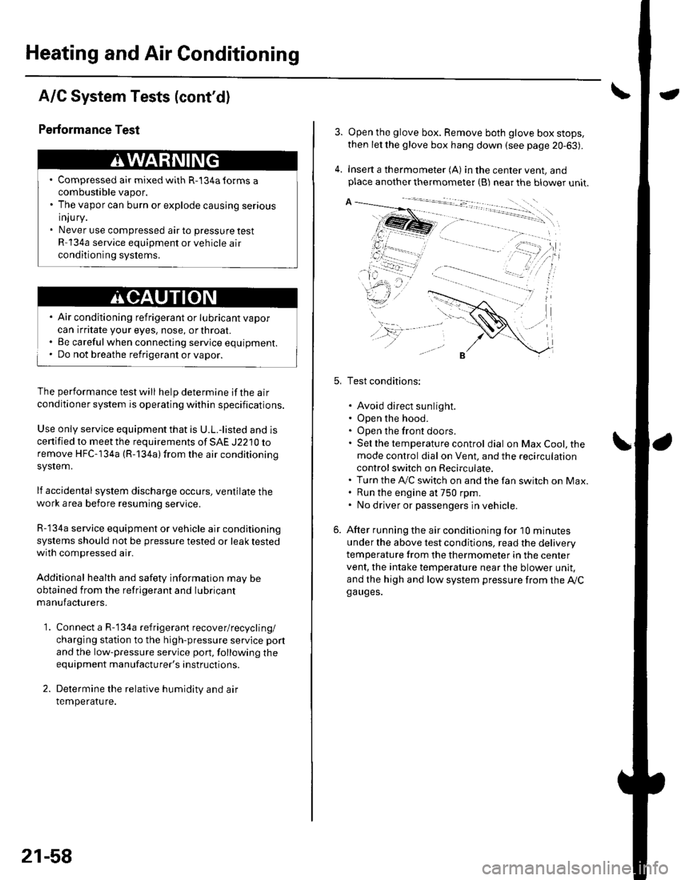
Open the glove box. Remove both glove box stops,
then let the glove box hang down (see page 20-63).
Insert a thermometer (A) in the center vent, andplace another thermometer {B) near the blower unit.
Test conditions:
. Avoid direct sunlight.. Open the hood.. Open the front doors.. Sel the temperature control dial on Max Cool, the
mode control dial on Vent, and the recirculation
control switch on Recirculate.. Turn the A,/C switch on and the fan switch on Max.. Run the engine at 750 rpm.. No driver or passengers in vehicle.
After running the air conditioning for I0 minutes
under the above test conditjons, read the delivery
temperature from the thermometer in the center
vent, the intake temperature near the blower unit,
and the high and low system pressure from the Ay'Cga uges.
Page 834 of 1139
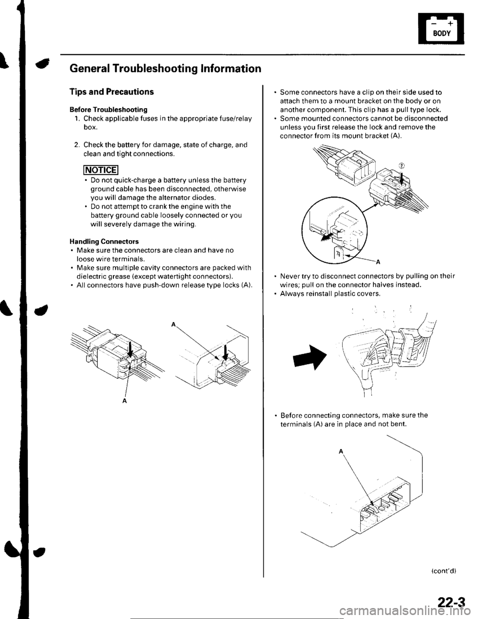
General Troubleshooting Information
Tips and Precautions
Bef ore Troubleshooting
1. Check applicable fuses in the appropriate fuse/relay
oox.
2. Check the battery for damage. state of charge, and
clean and tight connections.
. Do not quick-charge a battery unless the battery
ground cable has been disconnected, otherwise
you will damage the alternator diodes.. Do not attempt to crank the engine with the
battery ground cable loosely connected or you
will severely damage the wiring.
Handling Connectors. Make sure the connectors are clean and have no
loose wire terminals.. Make sure multiple cavity connectors are packed with
dielectric grease (except waterti ght connectors).. All connectors have push-down release type locks (A).
Some connectors have a clip on their side used to
attach them to a mount bracket on the body or on
another component. This clip has a pull type lock.
Some mounted connectors cannot be disconnected
unless you first release the lock and remove the
connector from its mount bracket (A).
Never try to disconnect connectors by pulling on their
wires; pull on the connector halves instead.
Alwavs reinstall Dlastic covers,
Before connecting connectors, make sure the
terminals (A) are in place and not bent.
(cont'd)
22-3
Page 838 of 1139
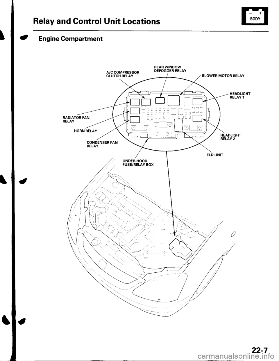
Relay and Control Unit Locations
Engine Compartment
RADIATOR FANRELAY
BLOWER MOTOR RELAY
HORN RELAY
CONDENSER FANRELAY
UNDER-HOODFUSE/RELAY BOX
\...
,-:1-'...
ELD UNIT
22-7