bulb HONDA CIVIC 2002 7.G Owner's Manual
[x] Cancel search | Manufacturer: HONDA, Model Year: 2002, Model line: CIVIC, Model: HONDA CIVIC 2002 7.GPages: 1139, PDF Size: 28.19 MB
Page 927 of 1139
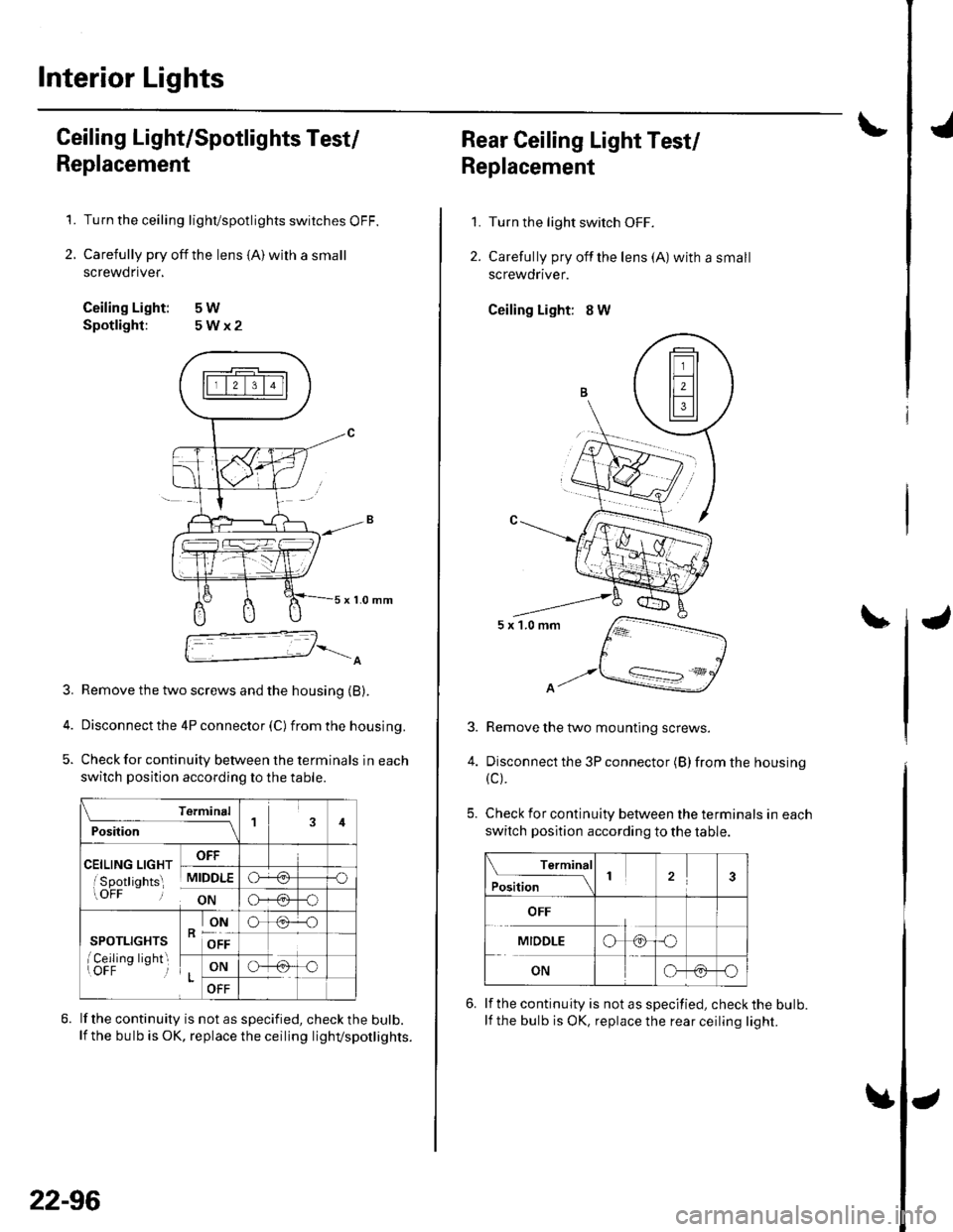
Interior Lights
Ceiling Light/Spotlights Test/
Replacement
Turn the ceiling lighvspotlights switches OFF.
Carefully pry off the lens {A) wilh a small
screwdnver,
Ceiling Light: 5W
Spotlight: 5Wx2
1.
2.
x 1-0 mm
3. Remove the two screws and the housing (B).
4. Disconnect the 4P connector (C) fromthehousing.
5. Check for continuity between the terminals in each
switch position according to the table.
\A
Terminal
P."lil;- -----_lil
celL,"c a,c", oFF
isoottiohts MIDDLE'uir oN
re-o
a}-+4-o
SPOTLIGHTS
I Ceilinq liohtroFF-- i
RONo(.F.O
OFF
LONG-
OFF
lf the continuity is not as specified, check the bulb.lf the bulb is OK, replace the ceiling lighvspotlig hts.
22-96
1.
2.
3.
4.
Rear Ceiling Light Test/
Replacement
Turn the light switch OFF.
Carefully pry offthe lens (A) with a small
screwdriver.
Ceiling Light: 8 W
5x1.0mm
A.
Remove the two mounting screws.
Disconnect the 3P connector (B) from the housing
{c).
Check for continuity between the terminals in each
switch position according to the table.
Terminal
Position123
OFF
MIDDLEo
ONG-@-O
lf the continuity is not as specified, check the bulb.
lf the bulb is OK, replace the rear ceiling light.
Page 928 of 1139
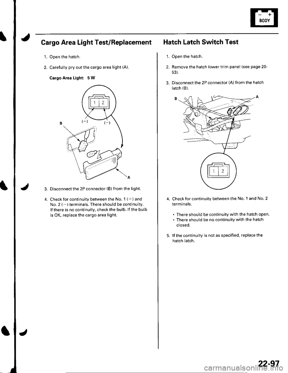
Cargo Area Light Test/Replacement
1.Open the hatch.
Carefully pry out the cargo area light (A).
Cargo Area Light: 5W
Disconnect the 2P connector (B) from the light.
Check for continuity between the No. 1 (+) and
No.2 ( )terminals. There should be continuity.
lf there is no continuitv, check the bulb. lf the bulb
is OK, replace the cargo area light.
'1.
Hatch Latch Switch Test
Open the hatch.
Remove the hatch lower trim panel (see page 20-
s3).
Disconnect the 2P connector {A) from the hatch
4.Check for continuity between the No. 1 and No. 2
terminals.
. There should be continuity with the hatch open
. There should be no continuity with the hatch
ctoseo.
lf the continuity is not as specified, replace the
hatch latch.
latch (B),
22-97
Page 993 of 1139
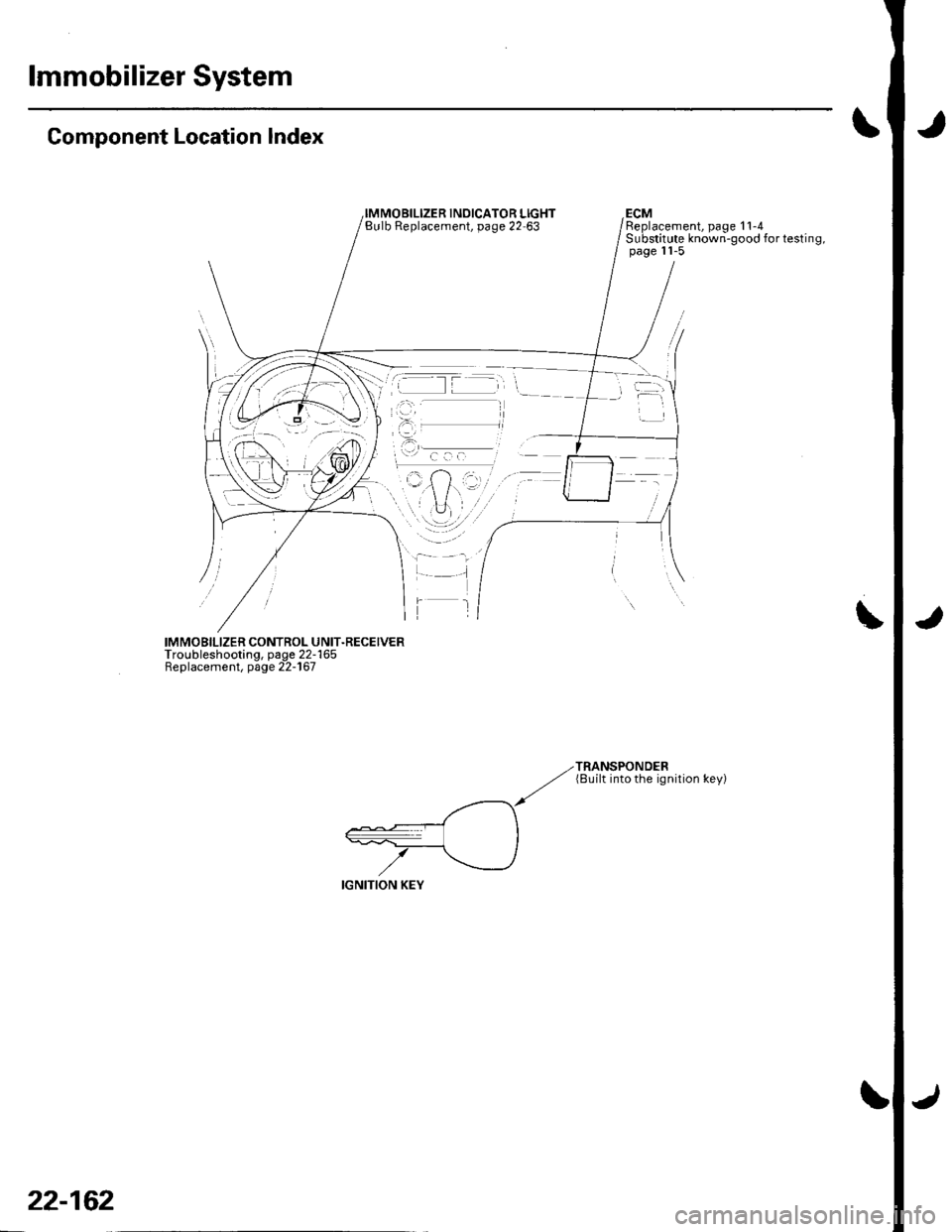
lmmobilizer System
Component Location Index
INOICATOR LIGHTBulb Replacement, page 22 63ECMReplacement, page 11-4Substitute known-good for testing,page 11-5
IMMOBILIZER CONTROL UNIT.RECEIVERTroubleshooting, page 22-165Replacement, page 22-167
TRANSPONDER(8uilt into the ignition key)
22-162
Page 1032 of 1139
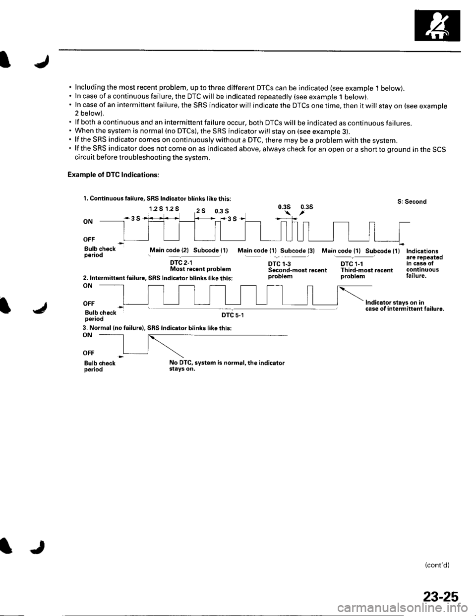
Including the most recent problem, up to three different DTCS can be indicated (see example 1 below).ln case of a continuous failure, the DTC will be indicated repeatedly {see example 1 below).In case of an intermittent failure, the SRS indicator will indicate the DTCS one time, then it will stay on (see example2 below).
lf both a continuous and an intermittent failure occur, both DTCS will be indicated as continuous failures.When the system is normal (no DTCS), the SRS indicator will stay on (see example 3).lf the SRS indicator comes on continuously without a DTC, there mav be a problem with the svstem.lf the SRS indicator does not come on as indicated above, always check for an open or a short to ground in the SCScircuit before troubleshooting the system.
Example of DTC Indications:
1. Continuous failure, SRS Indic6tor blink$ like this:
1.2 S 1,2 SS: Second0.3s 0.3s
ON
OFF
Bulb checkperiodMain code (21 Subcode l1)
DTC 2-lMost recent p.oblem
2. Intermittent failure, SRS lndicator blinks like this:ON
Main code l1lSubcode (3) Main code {11 Subcode {'l)Indicationsare lepeatedtn cese otcontinuousfailure.
lndicator stays on incase of i nterm ittent failu re.
(cont'd)
DTC 1-3DTC 1-1Sscond-mostrecent Third-mostrocentproblem problem
OFF
Bulb checkperiodDTC 5-1
3. Normal (no failure|, SRS Indicator blinks like this:ON
OFF
Bulb chockperiodNo DTC, systom is normal, the indicatorstays on.
0.3 s
23-25
Page 1037 of 1139
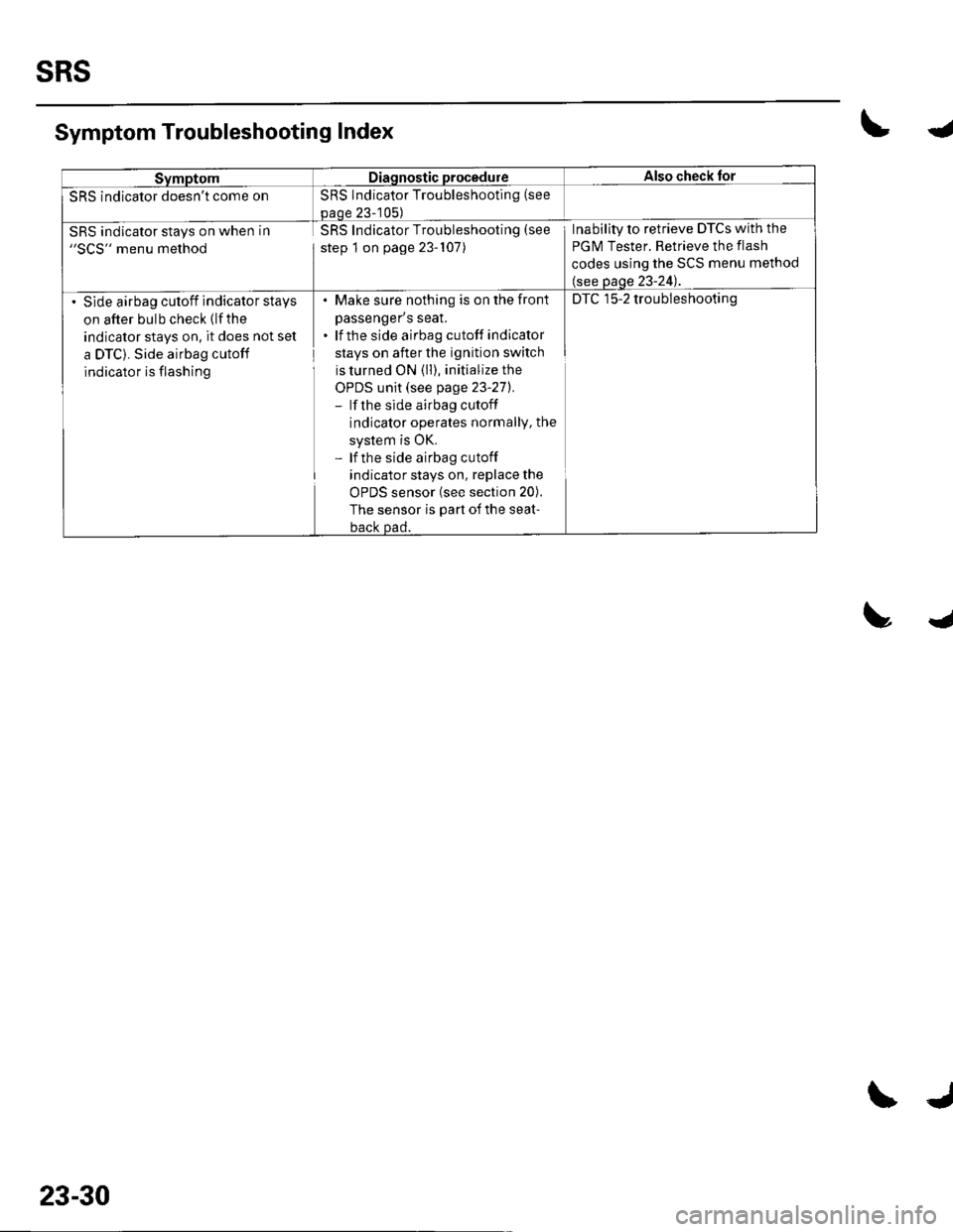
SRS
SymptomDiagnostic procedureAlso check for
SRS indicator doesn't come onSRS Indicator Troubleshooting (see
paoe 23-105)
SRS indicator stays on when in"SCS" menu method
SRS Indicator Troubleshooting (see
step 1 on page 23-107)
Inability to retrieve DTCs with the
PGM Tester. Retrieve the flash
codes using the SCS menu method
(see page 23-24).
Slde airbag cutoff indicator stays
on after bulb check (lfthe
indicator stays on, it does not set
a DTC). Side airbag cutoff
indicator is flashing
. Make sure nothing is on the fronl
passenger's seat.. lf the side airbag cutoff indicator
stays on after the ignition switch
is turned ON (ll), initialize the
OPDS unit (see page 23-271.- lf the side airbag cutoff
indicator operates normallY, the
system is OK.- lf the side airbag cutoff
indicator stays on, replace the
uFU5 SenSOr {See SeCrOn ZUl.
The sensor is part of the seat-
back Dad.
DTC 15-2 troubleshooting
Symptom Troubleshooting Index\4
trJ
23-30
\J
Page 1134 of 1139
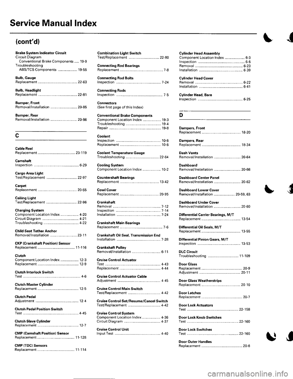
Service Manual Index
(cont'dl
Brake System Indicator CircuitCircuit DiagramConventional Brake Components..... 19-9TroubleshootingABS/TCS Components .... ....... ...... 19-55
Bulb, GeugeRep|acemenl................ .. ............2263
Bulb, HeadlightReplacement ......................................... 22-A1
Bumper, FrontRemoval/1nsra11ation ............................ 20 85
Bumper, RearRemoval/lnstallation... ... . .....20.86
Combination Light SwilchTesVReplacement ..............................22 80
Connecting Rod BearingsRep|acement...................... .......-....7-8
Connecting Rod Boltsf nspection ....................-.-.-.-.................... 7 -24
Connecting RodsInspection ........,,.,.,...,.,.,.,.,,,,.,,,.,.,.,.,.,.,.,.. 7 5
Connectors(See first page of this Index)
Conventional Brake Component3Component Location Index ................... 19'3Troub1eshootin9 ..................................... 19-4
Cylinder Head AssemblyComponent Location Index ..................... 6-3Inspection ................................................. 6 6Removal ..........&�23Insta11alion .............................................. 6 39
Cylinder Head Cover8emova1 ..............-.-................................. 6-22Installation ..............................................6-41
Cylinder Head, BareInspecton..,.....,.
D
c
Cable ReelReplacement....................................... 23-1 19
CamshaftInspection .......................-...-................... 6-29
Cargo Area LightTesVRep1acement ................................ 22-97
CarpetReplacement.....-...-..... ... ......-.20-55
Ceiling Light-estrReplacement ................................ 22.96
Charging SystemComponent Location Index................... 4-20Circuit Diagram ...................................... 4-21
19-8
CoolantInspection .................. ..... .. 106Replacement................. ... . .. 10 6
Coolant Temperature Gat|geTroub1eshootin9................................... 22 64
Cooling SyslemComponent Location Index................... 10-2
Countershaft BearingsReplacement............... ..................... 13-42
Cowl CoverReplacement............... .. ..... ....20-95
CrankshaftRemoval .................................................. 7 -12
Repair ..................
Inspec(on,,,,,........1 14
Dampers. FrontReplacement................ ..................... 18 20
Oampers, RearRep1acement......................................... 18-34
Dash VentsBemoval/lnstallation .-.......................... 20-64
DashboardBemoval/1nsta11ation ............................ 20-66
Oashboard Center PanelRemoval/1nstaf 1ation ............................ 20 62
Dashboard Lower CoverRemoval/lnstallation ...................... 20-59, 63
Dashboard Under CoverRemoval/lnstallation ............................ 20 60
Diff erential Carrier Bearings, M/TRep1acement,,......,...,...,.,.,,,.,.,,,........,.,. 13-54
Ditferential Oil Seals, M/T8ep1acement......................................... 13-55
Differential Pinion Gears, M/TInspection .,....-,.,,,.,..,.-,.,.........,.,.,,, 13 53
OLC CircuitTroubleshooting ................................ 1 1-109
Door GlassRep1acement.,.,,,,,,,,,,,.,,,,,,,,,,.,.,.,.,.,,,,,,.,, 20-9Adjustment. .. .....................20-11
Door Glass WeathelstripsReplacement .............-.. . . . ..........-......20 10
Door LatchesReplacement ..........-.-.............................. 20-7
Door Lock ActuatorsTest ...................................................... 22-154
Door Lock Knob SwitchesTest -......... . . . - . . . . . . . . ......22-160
Door Lock SwitchesTest ........... ............................ ............. 22-160
Door Outer HandlesRep1acemen1 ........................................... 20-6
3
Child Seat Tether AnchorRemoval/lnstaf lat;on .. ........................ 23 11
CKP (Crankshaft Position) SonsorReplacement....................................... 1 1-116
ClutchComponentLocation 1ndex................... 12-3Rep1acemen1........................................... 12-9
Clutch InteYlock SwitchTest.....-........-...-............. ...---.-.......4-6
Clutch Master CylinderReplacement........................................... 12 5
clutch PedalAdjustment ............................................. 12 4
Clutch Pedal Position SwitchTest.,.,,,,,.,,,.,.,,,,,,.,.,,,,,,,,,.,,,,,.. ......445
lnstallation.................. . ..... .....1-24
Crankshalt Main BearingsReplacement........-.-.................................. 7-6
CrankshaftOil Seal,Transmission End1nstanation .............................................. 7 28
Crankshafl PulleyRemoval/lnstallation -..................-.......... 6-1 1
Cruise Control Actuator
Troubleshooting
Clutch Slave CylindorBeplacemeit...
...................... 4-43
.......4-22
Test
12-1
RepIacement........................................... 4-44
Cruise Control Actuator CableAdjustment ............................................. 4 45
Cruise Control Main SwitchTesVRep1acement .................................. 4 42
Cruise Control Set/Resume/Cancel SwitchTesVRep1acement .................................. 4 42
Cruise Control SystomComponent Localion Inde\................... 4-36Circuit Diagram ....-................................. 4 37
Cruise Control UnitInputTest.............................. .. ...4,40CMP {Camshaft Positionl Senso]Replacement....-...-.............................. 1 1-128
CMP (TDC) SensorsReplacement............-.......................... 1 1 1 14