check engine light HONDA CIVIC 2002 7.G Owner's Manual
[x] Cancel search | Manufacturer: HONDA, Model Year: 2002, Model line: CIVIC, Model: HONDA CIVIC 2002 7.GPages: 1139, PDF Size: 28.19 MB
Page 602 of 1139

Parking Brake Check and Adiustment
Check
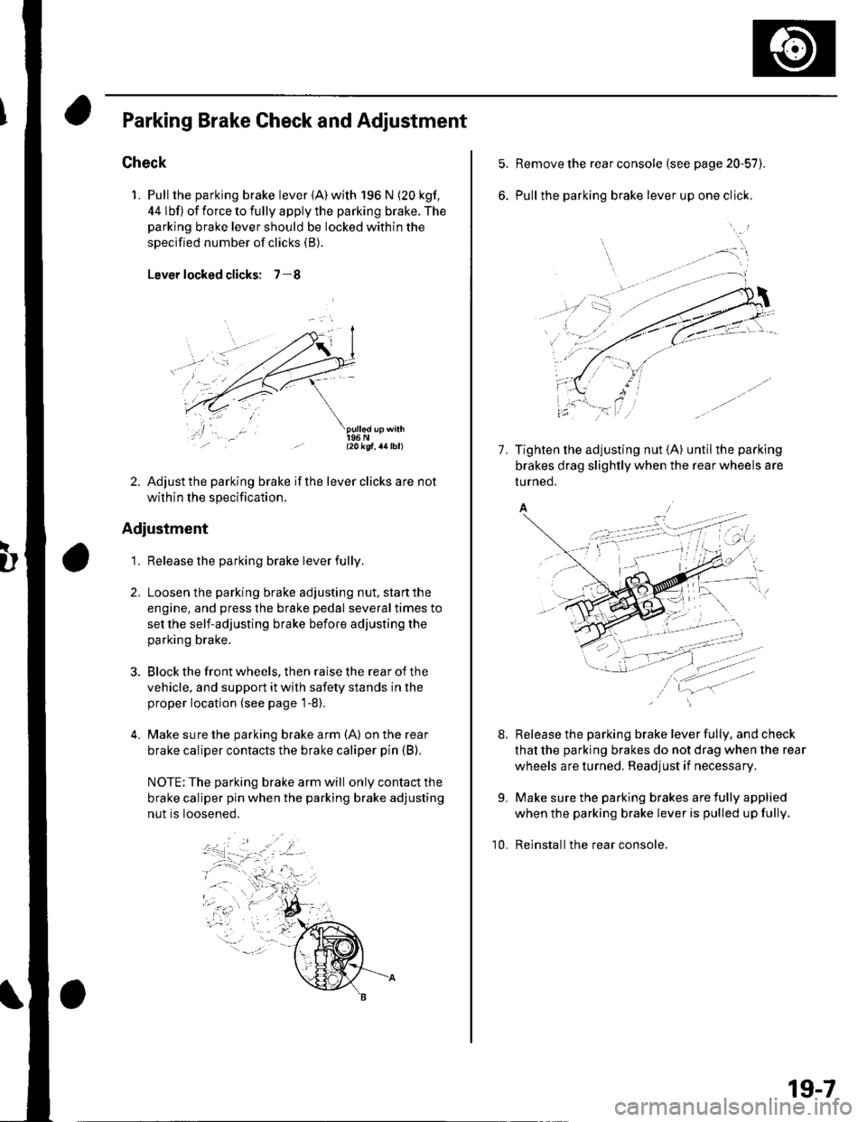
1. Pull the parking brake lever {A) with 196 N (20 kgf,
44 lbf) of force to fully apply the parking brake. The
parking brake lever should be locked within the
specified number of clicks (B).
Lever locked clicks: 7-8
- l2okqf, a4lbl)
2. Adjust the parking brake if the lever clicks are not
within the specification.
Adjustment
1. Release the parking brake lever fully.
Loosen the parking brake adjusting nut, start the
engine, and press the brake pedal several times to
set the self-adjusting brake before adjusting the
parking brake.
Block the front wheels, then raise the rear of the
vehicle, and support it with safety stands in the
proper location (see page 1-8).
Make sure the parking brake arm (A) on the rear
brake caliper contacts the brake caliper pin (B),
NOTE: The parking brake arm will only contact the
brake caliper pin when the parking brake adjusting
nut is loosened.
Remove the rear console {see page 20-57).
Pull the parking brake lever up one click,
7, Tighten the adjusting nut {A} until the parking
brakes drag slightly when the rear wheels are
tu rned.
A/
Release the parking brake lever fully, and check
that the parking brakes do not drag when the rear
wheels are turned. Readjust if necessary.
Make sure the parking brakes are fully applied
when the parking brake lever is pulled up fully.
Reinstall the rear console.
8.
9.
10.
19-7
Page 613 of 1139

Gonventional Brake Components
IBrake Booster Test
Functional Test
1. With the engine stopped, press the brake pedal
several times to deplete the vacuum reservoir, thenpress the pedal hard, and hold itfor 15 seconds. lfthe pedal sinks, either the master cylinder is
bypassing internally, or the brake system (master
cylinder, lines. modulator, or calipers) is leaking.
2. Start the engine with the brake pedal pressed. lf thepedal sinks slightly, the vacuum booster is workingproperly. lf the pedal height does not vary, thebooster or check valve is faulty.
3. With the engine running, press the brake pedal
lightly. lfthe brake pedal sinks more than 1O mm
{3/8 in, ) in 3 minutes, the master cylinder is faulty.A slight change in pedal height when the Ay'C
compressor cycles on and off is normal. (The A,/C
compressor load changes the vacuum available tothe booster.)
Leak Test
1. Press the brake pedal with the engine running, thenstop the engine. lf the pedal height does not vary
while pressed for 30 seconds, the vacuum boosteris OK. lf the pedal rises, the booster is faulty.
2. With the engine stopped, press the brake pedal
several times using normal pressure. When thepedal is first pressed, it should oe row.
On consecutive applications, the pedal height
should gradually rise. lfthe pedal position does notvarv, check the booster check valve.
19-18
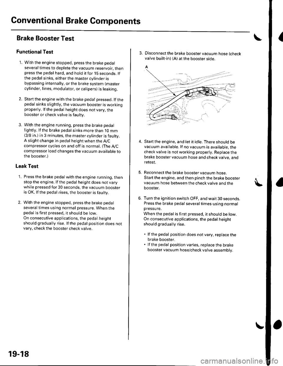
3. Disconnect the brake booster vacuum hose (check
valve built-in) (A) at the booster side.
5.
4.Start the engine, and let it idle. There should bevacuum available. lf no vacuum is available, thecheck valve is not working properly. Repiace thebrake booster vacuum hose and check valve, andrelesI.
Reconnect the brake booster vacuum nose.
Start the engine, and then pinch the brake boostervacuum hose between the check valve and thebooster,
Turn the ignition switch OFF, and wait 30 seconds,Press the brake pedal several times using normalpressu re,
When the pedal is first pressed, it should be low.On consecutive applications, the pedal height
should gradually rise.
. lf the pedal position does notvary, replacethe
brake booster.. lf the pedal position varies, replace the brake
booster vacuum hose/check valve assembly.
Page 876 of 1139

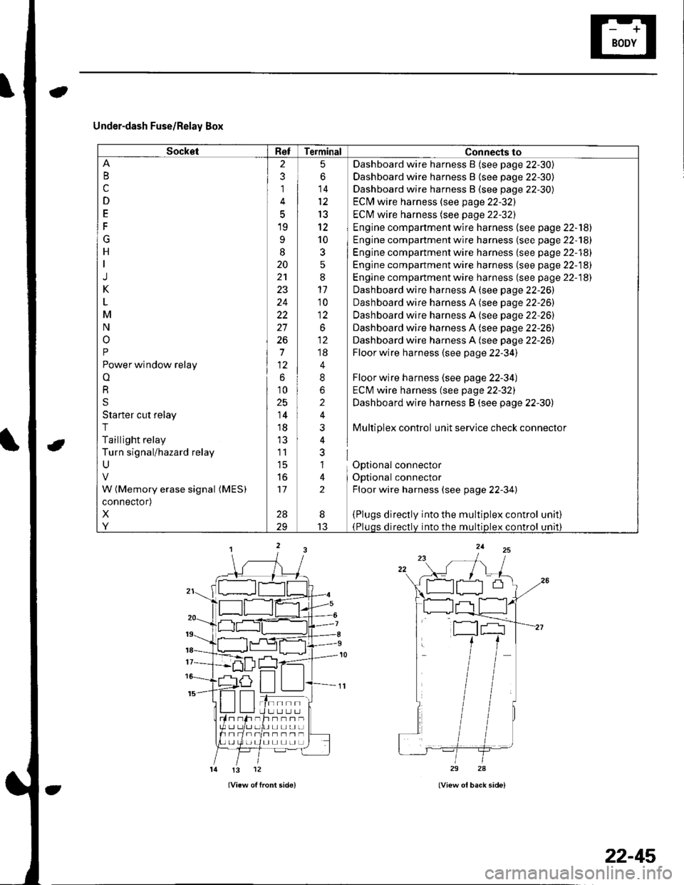
Under-dash Fuse/Relay Box
SocketRefTerminal Connects to
B
c
D
E
F
G
H
J
K
M
N
o
P
Power window relay
o
R
S
Starter cut relay
T
Taillight relay
Turn signal/hazard relay
U
W (Memory erase signal (MES)
connector)
X
Y
2
3
1
5
19
9
I
20
24
22
27
26
7
6
10
25
14
18
11
l5
to
17
28
5
6
14
13
12
10
3
:
11'10
1:
.o^
;;
4
8
2
i
nl
al
lt
2
Dashboard wire harness B {see page 22-30)
Dashboard wire harness B {see page 22-30)
Dashboard wire harness B (see page 22-30)
ECM wire harness (see page 22-32)
ECI\4 wire harness (see page 22-32)
Engine compartment wire harness (see page 22-'l8l
Engine compartment wire harness (se e page 22-181
Engine compartment wire harness (see page 22-18)
Engine compartment wire harness (se e page 22-18)
Engine compartment wire harness (see page 22-18)
Dashboard wire harness A (see page 22-26)
Dashboard wire harness A (see page 22-26)
Dashboard wire harness A (see page 22-26)
Dashboard wire harness A (see page 22-26)
Dashboard wire harness A (see page 22-26)
Floor wire harness (see page 22-34)
Floor wire harness (see page 22-34)
ECM wire harness (see page 22-32)
Dashboard wire harness B (see page 22-30)
Multiplex control unit service check connector
Optional connector
Optional connector
Floor wire harness (see page 22-34)
{Plugs directly into the multiplex control(Pluqs directlv into the multiDlex control
unat)
unrl)
I
13
tn--rlI U LI L.] L.Jh--n-UL]L]UL]
I] L] L] LI L]
!3 12
22-45
Page 996 of 1139

)
I
Troubleshooting
Before troubleshooting the immobilizer system,
troubleshoot any EClvl Diagnostic Trouble Codes (DTCS)
(see page 11-3), and make sure the ECM has no
malfunction.
Note these items before trou bleshooting:
. Due to the action of the immobilizer system, the
engine takes slightly more time to start than on a
vehicle without an immobilizer system.. When the system is normal, and the proper key is
inserted, the indicator light comes on for 2 seconds,
then it will go off.. If the indicatorstartsto blink after 2 seconds, or if the
engine does not start. remove any other immobilizer
keys or large key fobs on the key ring, then repeat the
starting procedure.
lf the engine still does not start, continue with thisprocedure.
1. Turn the ignition switch ON {ll) with proper key.
2. Check to see if the immobilizer indicator light
comes on.
Does the indicator light blink?
YES Disconnect the 7P connector from the
immobilizer control unit-receiver, then go to step 9.
NO Check for these problems, then go to step 3.
. Blown No. 9 (10A)fuse in the under-hood
fuse/relay box.I. An open in the wire between the gauge assembly
and the immobilizer control unit-receiver.l. A faulty immobilizer indicator light,I. An open in the wire between the gauge assembly
and the under-hood fuse/relay box.l
Remove the driver's dashboard lower cover (see
page 20-59).
Remove the steering column lower cover (see page
11-9).
l
-_--t
22-165
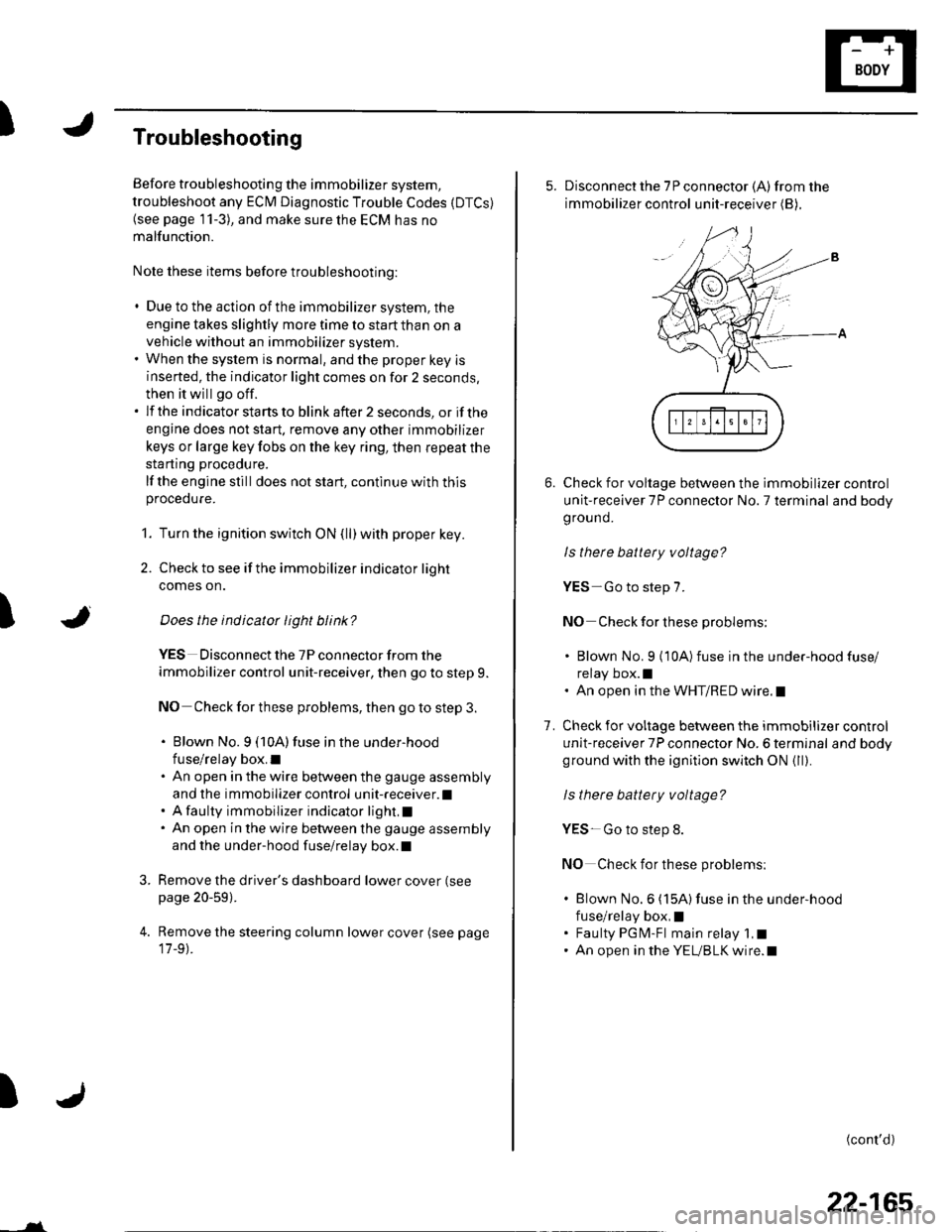
5. Disconnect the 7P connector (A)from the
immobilizer control unit-receiver (B),
Check for voltage between the immobilizer control
unit-receiver 7P connector No. 7 terminal and body
ground.
ls there battery voltage?
YES-Go to step 7.
NO Check for these problems;
. Blown No. 9 {10A)fuse in the under-hood fuse/
relay box.l. An open in the WHT/RED wire.l
Check for voltage between the immobilizer control
unit-receiver 7P connector No. 6 terminal and bodyground with the ignition switch ON {ll).
ls there battery voltage?
YES- Go to step 8.
NO Check for these problems:
. Blown No.6 (15A)fuse in the under-hood
fuse/relay box,I. Faulty PGM-Fl main relay 1,t. An open in the YEUBLK wire.l
1.
(cont'd)