check engine light HONDA CIVIC 2002 7.G User Guide
[x] Cancel search | Manufacturer: HONDA, Model Year: 2002, Model line: CIVIC, Model: HONDA CIVIC 2002 7.GPages: 1139, PDF Size: 28.19 MB
Page 301 of 1139
PGM-FI System
DTC Troubleshooting (cont'dl
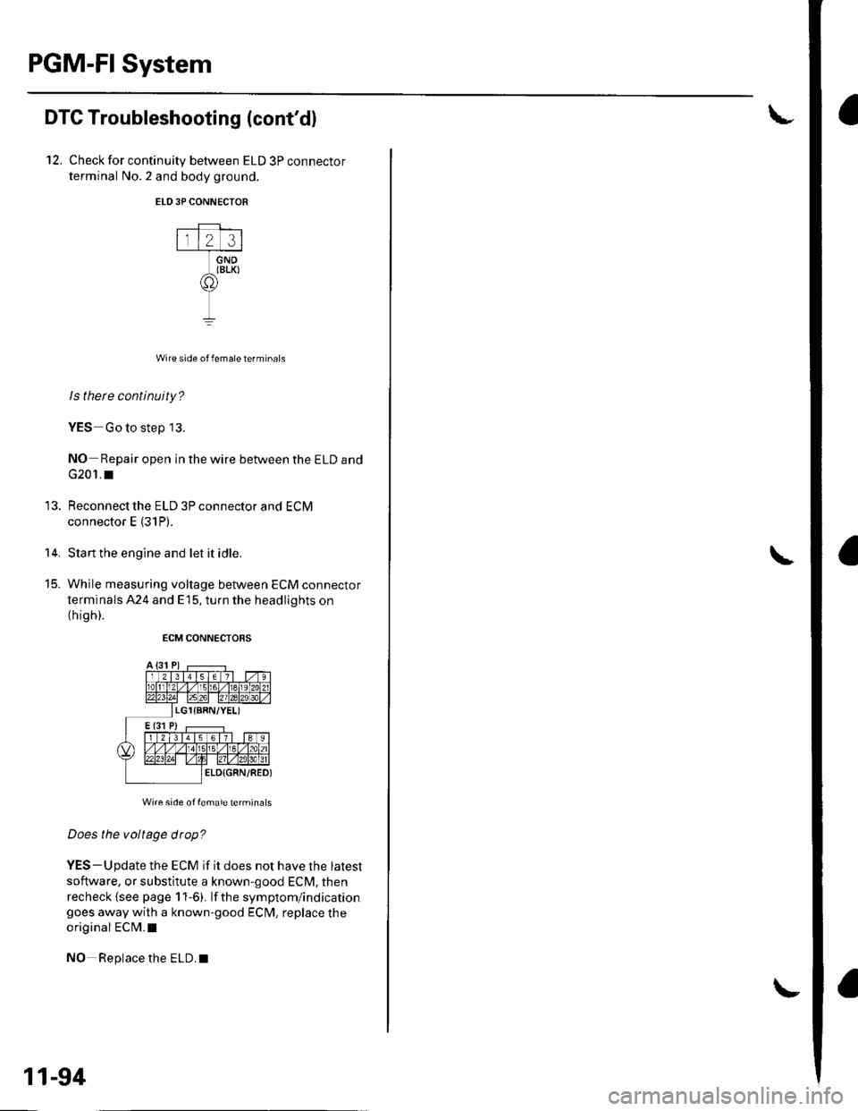
12, Check for continuity between ELD 3P connector
terminal No.2 and body ground.
ELD3P CONNECTOR
Wire side of female terminals
ls there continuity?
YES Go to step 13.
NO- Repair open in the wire between the ELD and
G201. I
Reconnect the ELD 3P connector and ECM
connector E (31P).
Start the engine and let it idle.
While measuring voltage between ECM connector
terminals 424 and E15, turn the headlights on
th igh).
ECM CONNECTORS
Wi.e side of female terminals
Does the voltage drop?
YES-Update the ECM if it does not have the latest
software, or substitute a known-good ECM, then
recheck {see page 1 1-6). lf the symptom/indicationgoes away with a known-good ECM, replace the
original ECM.I
NO Replace the ELD.I
14.
t5_
11-94
Page 326 of 1139
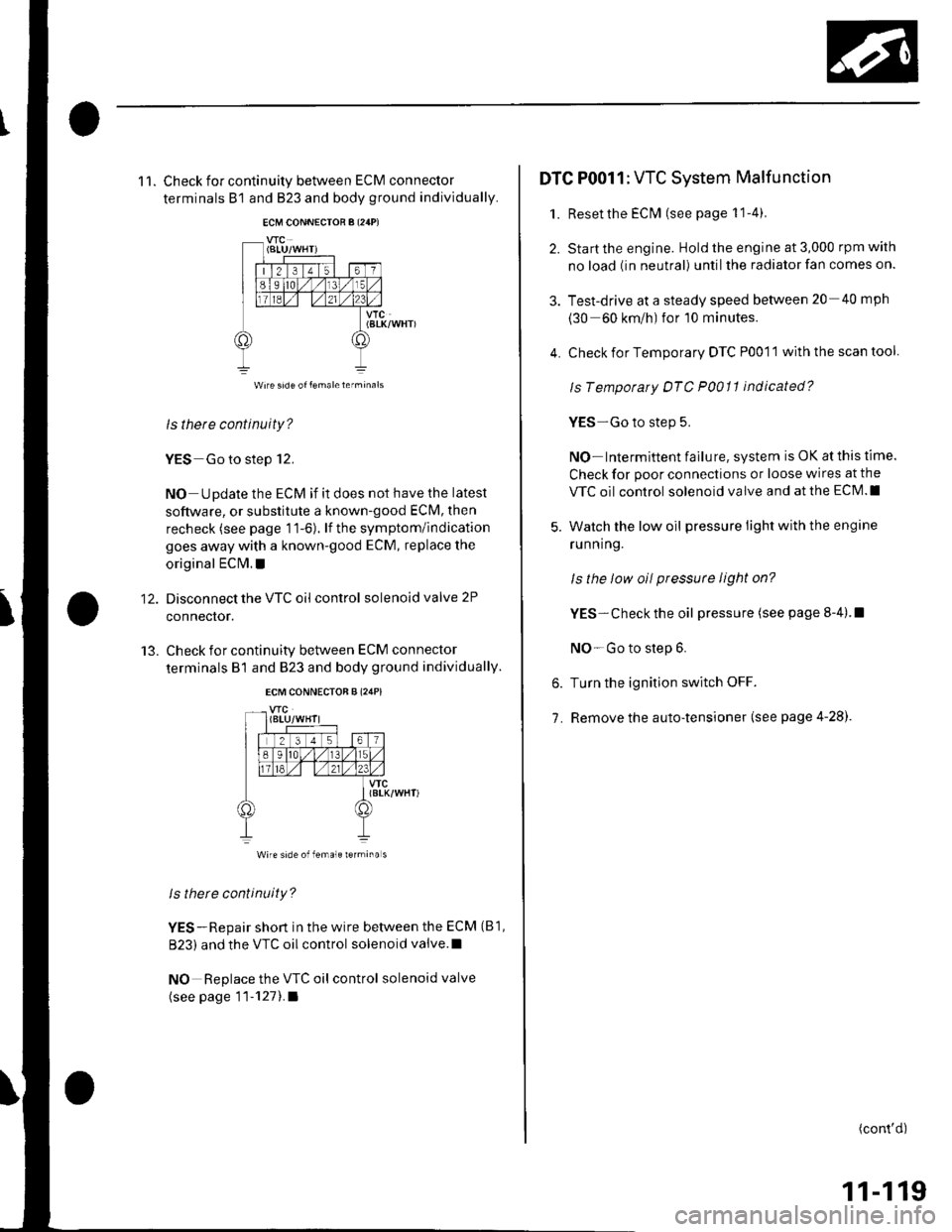
11. Check for continuity between ECM connector
terminals B1 and B23 and body ground individually.
VTC(BtK/WHT)
ls there continuity?
YES Go to step 12.
NO Update the ECM if it does not have the latest
software, or substitute a known-good ECM, then
recheck (see page 11-6). lf the symptom/indication
goes away with a known-good ECM, replace the
original EClvl. !
Disconnect the VTC oil control solenoid valve 2P
connector.
Check for continuity between ECM connector
terminals B1 and 823 and body ground individually.
12.
13.
vfc(8LK/WHT)
Wire side of female rermina s
ls there continuity?
YES-Repair short in the wire between the ECM (B1,
B23) and the VTC oil control solenoid valve.l
NO Replace the VTC oil control solenoid valve
(see page 11-1211.a
4.
DTC P0011: VTC System Malfunction
1. Reset the EClvl (see page 1 1-4).
2. Start the engine. Hold the engine at 3,000 rpm with
no load (in neutral) until the radiator fan comes on.
3. Test-drive at a steady speed between 20 40 mph
(30 60 km/h) for 10 minutes.
Check for Temporary DTC P0011 with the scan tool
ls Tempotaty DTC P0011 indicated?
YES-Go to step 5.
NO- Intermittent failu re, system is OK at this time.
Check for poor connections or loose wires at the
VTC oil control solenoid valve and at the ECM.I
Watch the low oil pressure light with the engine
ru n n ing.
ls the low oil pressute light on?
YES- Check the oil pressure (see page 8-4).I
NO-Go to step 6.
Turn the ignition switch OFF.
Remove the auto-tensioner (see page 4-28).
6.
7.
(cont'd)
11-119
Page 337 of 1139
ldle Control System
DTC Troubleshooting
DTC P0505: ldle Control System Malfunction
NOTE: lf DTC P1519 is stored atthe same time as DTC
P0505, troubleshoot DTC P1519 first, then recheck for
DTC P0505.
1. Start the engine. Hold the engine at 3,000 rpm with
no load (in neutral) until the radiator fan comes on,
then let it idle,
2. Checkthe engine speed at idle with no,load
conditions: headlights, blower fan, rear defogger,
radiator fan, and air conditioner off.
Is the engine running at 750t50 rpm?
YES - Intermittent failure, system is OK at this
trme.I
NO lf the idle speed is less than 700 rpm, go to
step 3; if it's 800 rpm or higher, go to step 4.
3. Disconnect the idle air control {lAC) valve3P
connector.
Does the engine speed increase or fluctuate?
YES- Check the idle speed {see page 1 1-138). lf the
idle will not adjust properly, clean the passage in
the throttle body, and then adjust the idle. I
NO- Replace the IAC valve.I
4. Turn the ignition switch OFF.
5. Remove the intake air duct from the throttle body.
6. Start the engine, and let it idle.
11-130
(
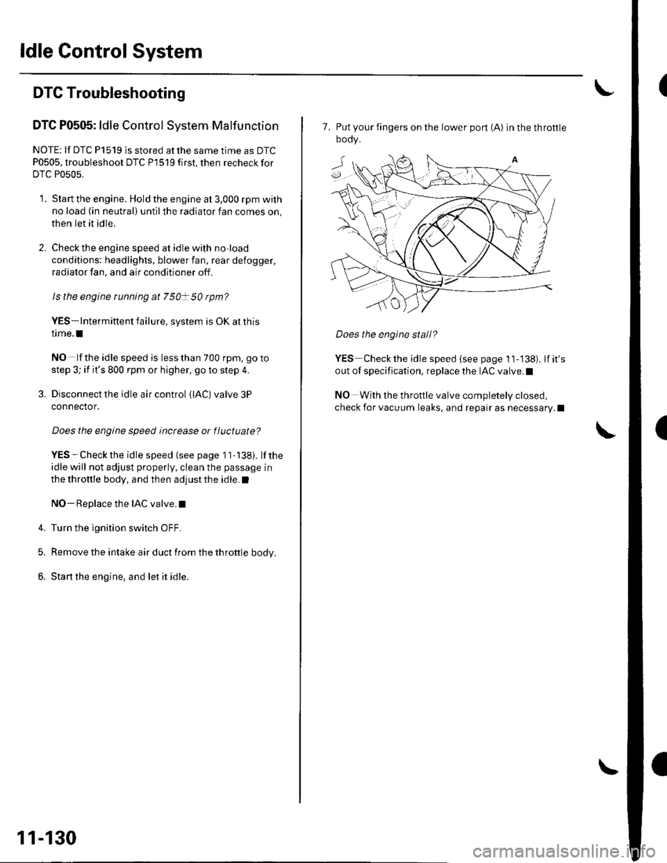
7. Put your fingers on the lower pon (A) inthethrottle
oooy.
Does the engine stall?
YES Checkthe idle speed (see page 11-138). lfit's
out of specification, replace the IAC valve.l
NO With the throttle valve completely closed,
check for vacuum leaks, and repair as necessary.l
Page 341 of 1139
ldle Gontrol System
't.
Alternator FR Signal Circuit Troubleshooting
Disconnect the alternator 4P connector from the
alternalor.
Turn the ignition switch ON {ll).
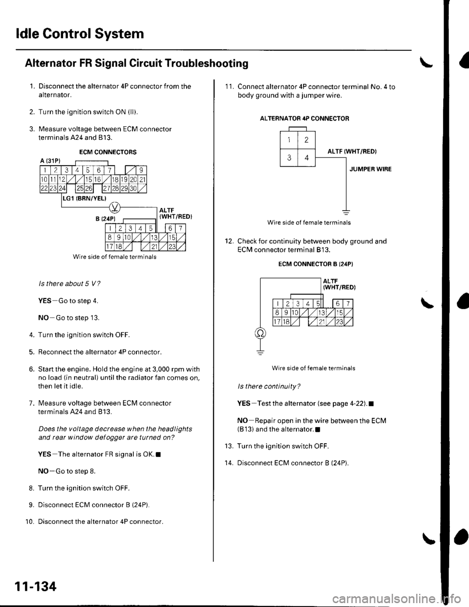
Measure voltage between ECM connector
terminals 424 and 813.
ECM CONNECTORS
2.
3.
A l31Pl
1 21345611 | 1.,'I
1011112,/56,/r8119l2C21
2312428129130
L(BRN/YEL)
ALTF(WHT
213 4t561
89ltal,/l/15
Wire side of female terminals
ls there about 5 V?
YES Go to step 4.
NO-Go to step 13.
4. Turn the ignition switch OFF.
5. Reconnect the alternator 4P connector.
6. Slan the engine. Hold the engine at 3,000 rpm with
no load (in neutral) until the radiator fan comes on,
then let it idle.
7. lvleasure voltage between ECM connector
terminals A24 and B 13.
Does the voltage decrease when the headlights
and rear window defogger arc tutned on?
YES The alternator FR signal is OK.l
NO-Go to step 8.
8. Turn the ignition switch OFF.
9. Disconnect ECM connector B (24P).
10. Disconnect the alternator 4P connector.
/REDI
11-134
'11. Connect alternator 4P con necto r term inal No.4 to
body ground with a jumper wire.
ALTERNATOR 4P CONNECTOR
12
ALTF34IWHT/RED)
JUMPER WIRE
12.
Wire side of female terminals
Check for continuity between body ground and
EClvl connector terminal 813.
ECM CONNECTOB B (24PI
Wire side of female terminals
ls there continuity?
YES-Testthe alternator (see page 4-22).1
NO Repair open in the wire between the ECM(B 13) and the alternator.l
Turn the ignition switch OFF.
Disconnect ECM connector B (24P).
\
13.
't 4.
Page 345 of 1139
ldle Control System
ldle Speed lnspection
NOTE:' Leave the idle air control (lAC) valve connecled.. Before checking the idle speed, check these items:- The malfunction indicator lamp (MlL) has not been
reported on.- lgnition timing- Spark plugs- Air cleaner- PCV system. Pullthe parking brake lever up. Start the engine, and
make sure the headlights are off.
1. Disconnect the evaporative emission (EVAP)
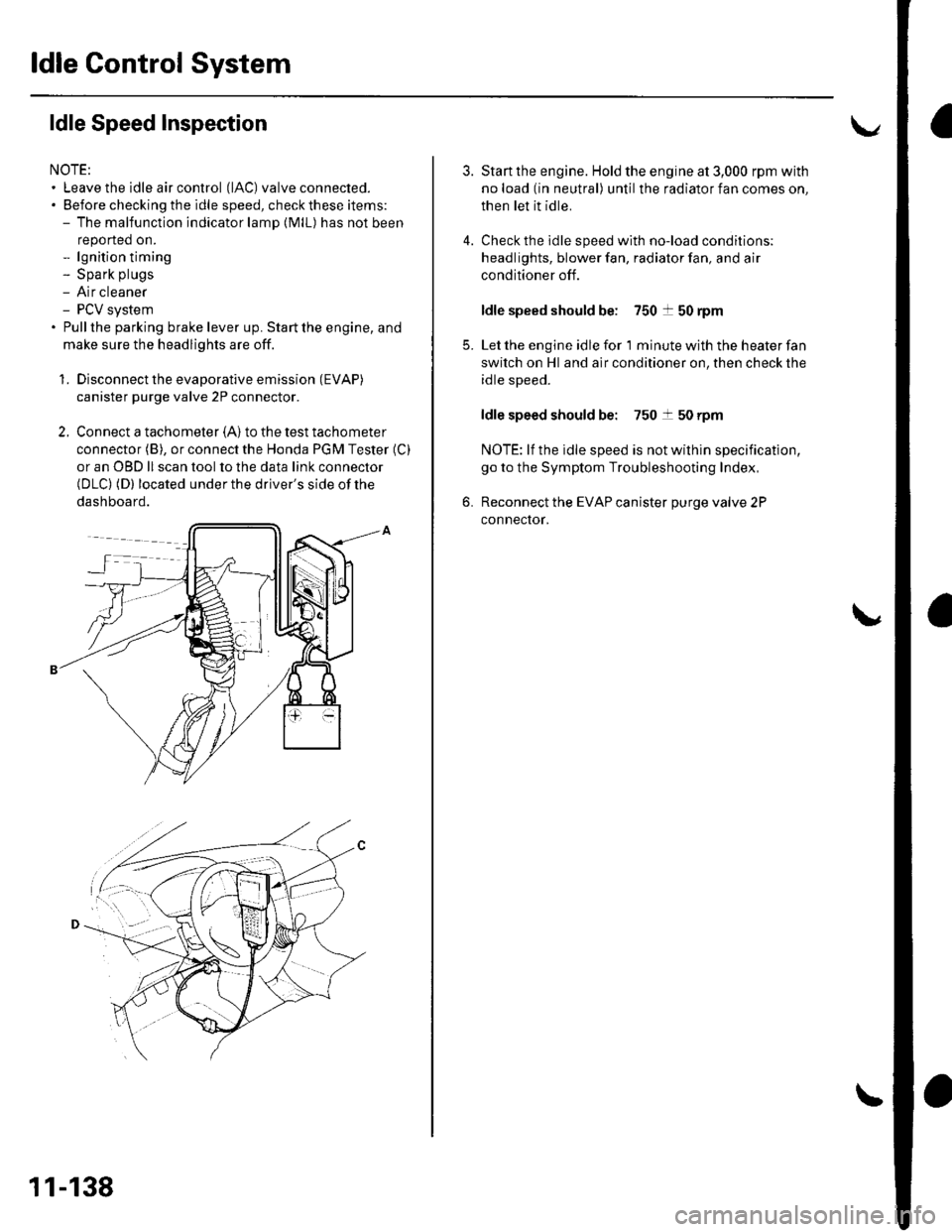
canister purge valve 2P connector.
2. Connect a tachometer (A)to the test tachometer
connector (B), or connect the Honda PGM Tester (C)
or an OBD ll scan tool to the data link connector(DLC) (D) located under the driver's side of the
dashboard.
11-138
4.
3.
5.
6.
Start the engine. Hold the engine at 3,000 rpm with
no load (in neutral) until the radiator fan comes on,
then let it idle.
Check the idle speed with no-load conditions;
headlights, blower fan, radiator fan, and air
conditioner off.
ldle speed should be: 750 t 50 rpm
Let the engine idle for 1 minute with the heater fan
switch on Hl and air conditioner on, then check the
idle speed.
ldle speed should be: 750 t 50 rpm
NOTE: lf the idle speed is not wilhin specification,
go to the Symptom Troubleshooting Index,
Reconnect the EVAP canister purge valve 2P
connector.
Page 382 of 1139
DTC Pl456: EVAP Control(Fuel Tank Svstem)
System Leakage
The fuel system is designed to allow specified
maximum vacuum and pressure conditions. Do not
deviate from the vacuum and pressure tests as
indicated in these procedures. Excessive pressure/
vacuum would damage the EVAP components or cause
eventual fuel tank failure.
Special Tools Required
Vacuum Pump/Gauge, 0-30 in. Hg A973X-041-XXXXX
This is a two-trip code. Once cleared, it cannot be
reproduced in one trip. Also, cenain specific driving
and ambient conditions must occur before the ECM will
complete the system checks. Additional test drives may
still not meet the specific conditions needed to
reproduce the code.
Follow these troubleshooting procedures carefully to
ensure the integrity of the system and to confirm the
cause of the problem or code.
NOTE: Fresh fuel has a higher volatility that createsgreater pressure/vacuum. The optimum condltlon for
testing is fresh fuel, and must be less than a full tank. lf
possible, to assist in leak detection, add 1 gallon of
fresh fuel to the tank (as long as it will not fill the tank).just before starting these procedures.
Fuel Fill Cap Check
1. Check the fuel fill cap (the cap must say "lf not
tightened 3 clicks check engine light may come
on" ).
ls the proper luel till cap installed and properly
tightened?
YES Go to step 2.
NO- Replace or tighten the cap.I
2. Check the fuel fill cap seal.
ls the tuel fill cap seal missing or damaged?
YES- Replace the fuel fill cap.I
NO The fuelfill cap is OK. Go to step 3.
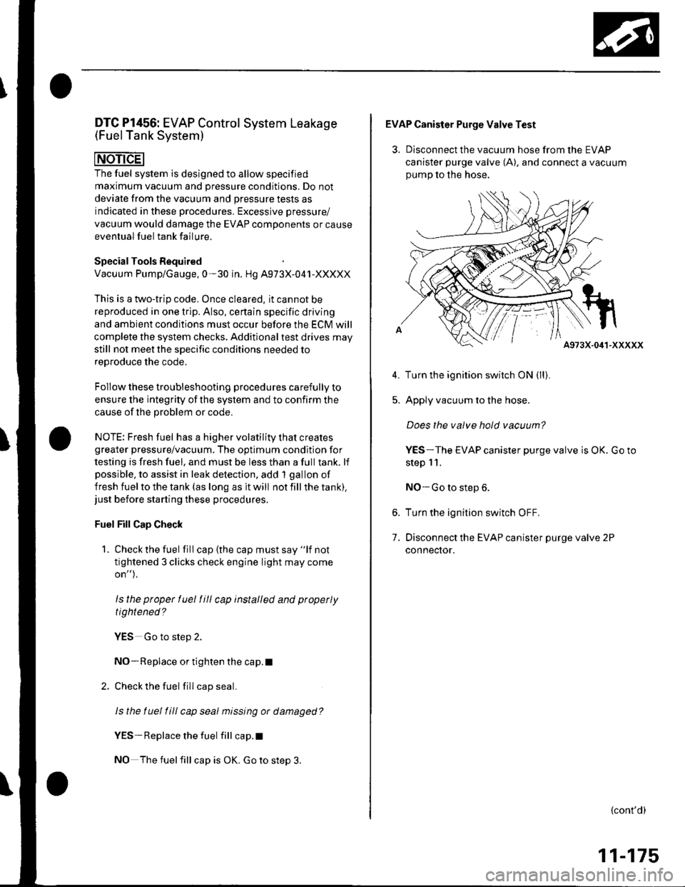
EVAP Canister Purge Valve Test
3. Disconnect the vacuum hose from the EVAP
canister purge valve (A), and connect a vacuum
oumo to the hose.
A973X-041-XXXXX
Turn the ignition switch ON (ll).
Apply vacuum to the hose.
Does the valve hold vacuum?
YES-The EVAP canister purge valve is OK. Go to
step 11.
NO-Go to step 6.
Turn the ignition switch OFF.
Disconnect the EVAP canister purge valve 2P
connecror.
5.
7.
{cont'd)
11-175
Page 413 of 1139
Transmission Fluid Inspection and
Replacement
'1. Park the vehicle on level ground, and turn the
engine OFF.
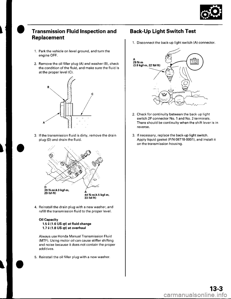
2. Remove the oilfiller plug (A) and washer (B), check
the condition of the fluid, and make sure the fluid is
at the proper level (C).
lf the transmission fluid is diny, remove the drain
plug (D) and drain the fluid.
A44 N.m{4.5 kgt.m,33 rbr.ftl
Reinstall the drain plug with a new washer, and
refill the transmission fluid to the proper level.
Oil Capacity
1.5 0 (1.6 US (F) at tluid change
1.7 0 {1.8 US qt) at overhaul
Always use Honda Manual Transmission Fluid
(MTF). Using motor oil can cause stiffer shifting
and noise because it does not contain the proper
additives.
Reinstall the oil filler plug with a new washer.5.
13-3
Back-Up Light Switch Test
1. Disconnectthe back-up light switch (A) connector.
Check for continuity between the back up light
swilch 2P connector No. 1 and No.2 terminals.
There should be continuity when the shift lever is in
reverse.
lf necessary, replace the back-up light switch.
Apply liquid gasket (P/N 08718-0001), and install it
on the transmission housing.
2.
3.
Page 587 of 1139
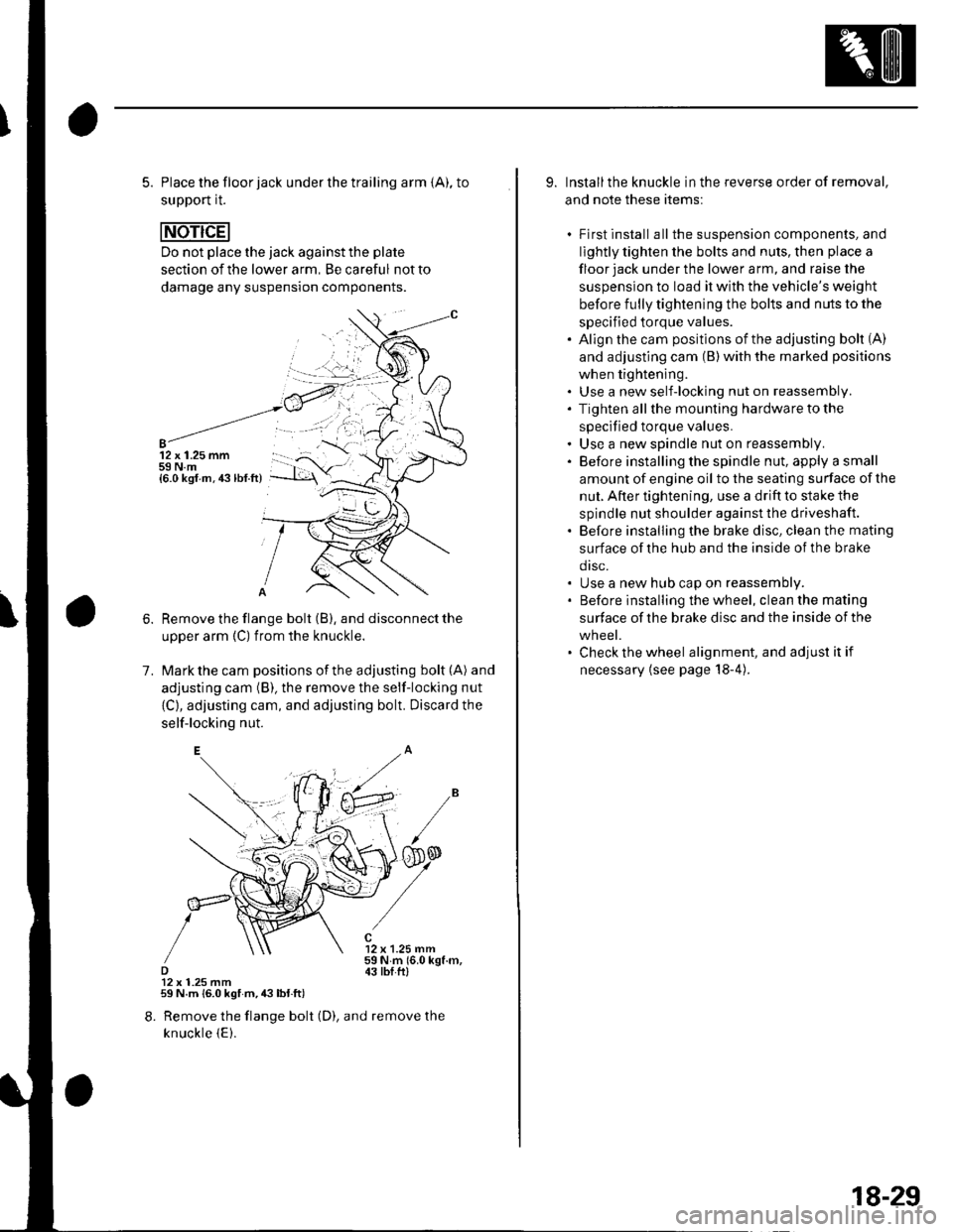
5. Place the floor jack under the trailing arm {A), to
support it.
Do not place the jack against the plate
section of the lower arm, Be careful not to
damage any suspension components.
12 x 1.25 mm59 N.m{6.0 ksf.m.43lbf.ft)
1.
Remove the flange bolt (B), and disconnect the
upper arm {C) from the knuckle.
Mark the cam positions of the adjusting bolt (A) and
adjusting cam (B), the remove the self-locking nut
{C}, adjusting cam, and adjusting bolt. Discard the
self-locking nut.
12 x 1.25 mm59Nm(6.0kgf.m,43 tbI.ftl12 x 1.25 mm59 N.m {6.0 kgf m,43lbl.ft)
8. Remove the flange bolt (D), and remove the
knuckle {E).
9. Installthe knuckle in the reverse order of removal,
and note these items:
. First install all the suspension components, and
lightly tighten the bolts and nuls, then place a
floor jack under the lower a rm, and raise the
suspension to load it with the vehicle's weight
before fully tightening the bolts and nuts to the
specified torque values.. Align the cam positions of the adjusting bolt (A)
and adjusting cam (B) with the marked positions
when tightening.. Use a new self-locking nut on reassembly.. Tighten allthe mounting hardware to the
specified torque values.. Use a new spindle nut on reassembly.. Before installing the spindle nut, apply a small
amount of engine oil to the seating surface of the
nut. After tightening, use a drift to stake the
spindle nut shoulder against the driveshaft.. Before installing the brake disc, clean the mating
surface of the hub and the inside of the brake
drsc.. Use a new hub cap on reassembly.. Before installing the wheel, clean the mating
surface of the brake disc and the inside of the
wheel.. Check the wheel alignment, and adjust it if
necessary {see page 18-4).
18-29
Page 599 of 1139
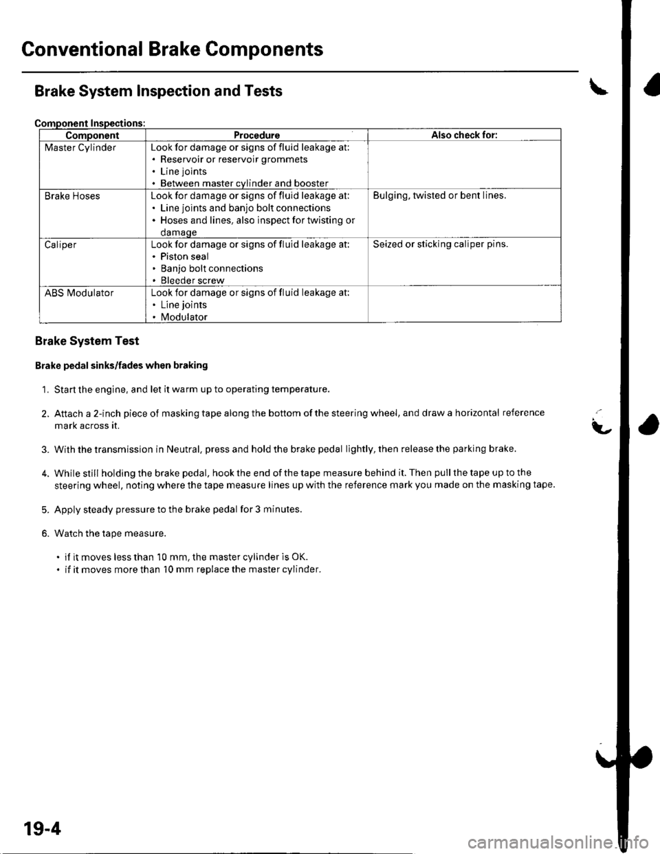
Gonventional Brake Components
ComponentProcedureAlso check for:
l\4aster CylinderLook for damage or signs of fluid leakage at;. Reservoir or reservoir grommets
. Line joints
. Between master cvlinder and booster
Brake HosesLook for damage or signs of fluid leakage at:. Line joints and banjo bolt connections. Hoses and lines. also inspect for twisting or
damaqe
Bulging, twisted or bent lines.
CaliperLook for damage or signs of fluid leakage at:. Piston seal. Banjo bolt connections. Bleeder screw
Seized or sticking caliper pins.
ABS l\ilodulatorLook for damage or signs of fluid leakage at:. Line joints
. Modulator
Brake System Inspection and Tests
Brake System Test
Brake pedal sinks/fades when braking
1. Start the engine, and let it warm up to operating temperature.
2. Attach a 2-inch pieceof masking tape along the bottom of the steering wheel, and draw a horizontal reference
mark across it.
With the transmission in Neutral, press and hold the brake pedal lightly, then release the parking brake.
While still holding the brake pedal, hook the end of the tape measure behind it. Then pull the tape up to the
steering wheel, noting where the tape measure lines up with the reference mark you made on the masking tape.
Apply steady pressure to the brake pedal for 3 minutes.
Watch the tape measure.
. if it moves less than 10 mm, the master cylinder is OK.
. if it moves more than 10 mm replace the master cylinder.
t-
3.
5.
6.
19-4
Page 601 of 1139
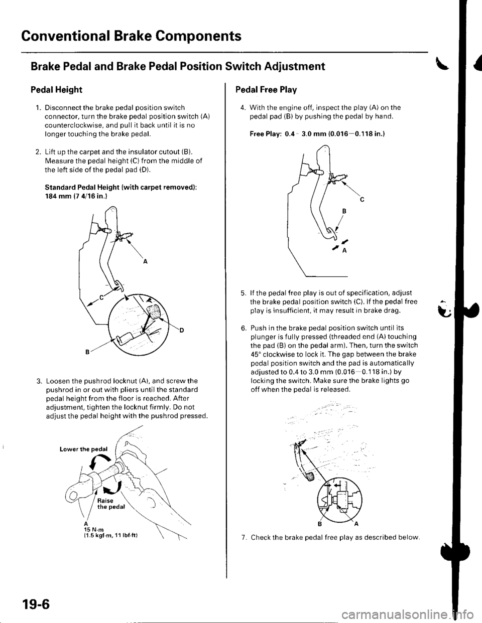
Conventional Brake Components
Brake Pedaland Brake PedalPosition Switch Adjustment
Pedal Height
1.Disconnect the brake pedal position switch
connector, turn the brake pedal position switch (A)
counterclockwise, and pull it back until it is no
longer touching the brake pedal.
Lift up the carpet and the insulator cutout (B).
l\4easure the pedal height (C) from the middle of
the left side of the pedal pad (D).
Standard Pedal Height (with carpet removed):
184 mm (7 4/16 in.)
Loosen the pushrod locknut (A), and screw the
pushrod in or out with pliers until the standard
pedal height from the floor is reached. After
adjustment, tighten the locknut firmly. Do not
adjust the pedal height with the pushrod pressed.
15 N.m(1.5 kgl m. 11 lbl ft)
19-6
7. Check the brake pedal free play as described below.
Pedal Free Play
4. With the engine off, inspect the play (A) on the
pedal pad (B) by pushing the pedal by hand.
Free Play: 0.4- 3.0 mm {0.016 0.'l18in.)
lf the pedal free play is out of specification, adjust
the brake pedal position switch (C). lf the pedal free
play is insufficient, it may result in brake drag.
Push in the brake oedal oosition switch until its
plunger is fully pressed (threaded end (A)touching
the pad (B) on the pedal arm). Then, turn the switch
45" clockwise to lock it. The gap between the brake
pedal position switch and the pad is automatically
adjusted to 0.4 to 3.0 mm (0.016 0.118 in.) by
locking the switch. Make sure the brake lights go
otf when the pedal is released.
t
6.