EVAP canister HONDA CIVIC 2002 7.G Owner's Guide
[x] Cancel search | Manufacturer: HONDA, Model Year: 2002, Model line: CIVIC, Model: HONDA CIVIC 2002 7.GPages: 1139, PDF Size: 28.19 MB
Page 390 of 1139
25.
26.
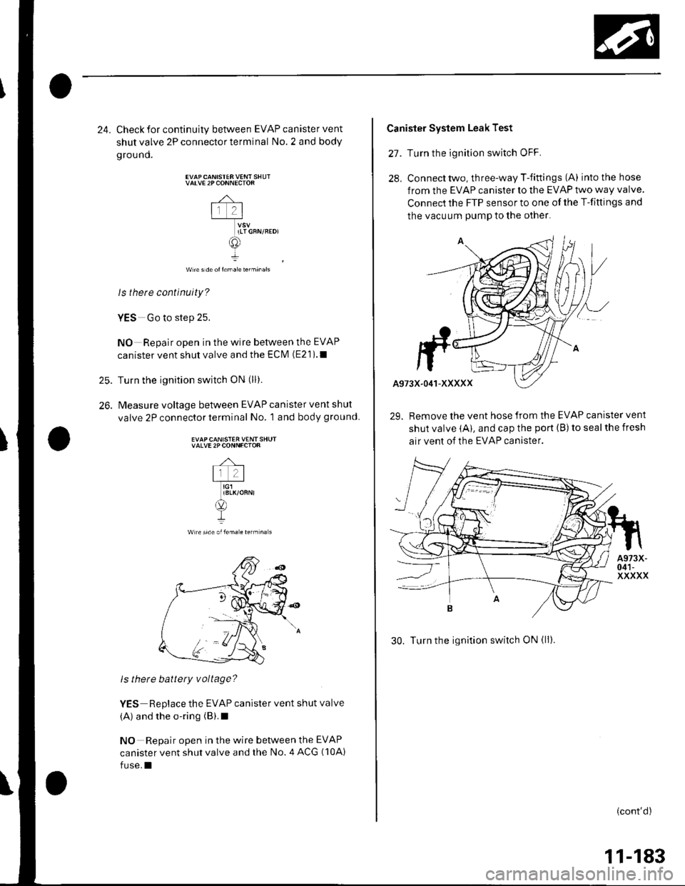
24. Check for continuity between EVAP canister vent
shutvalve 2Pconnectorterminal No.2 and body
ground.
VATVE 2P CONNECTOR
-4-
lr 2l-T_*u
ILTGFN/REDI
@
wn€ s de ol l€ma1e terminals
ls therc continuity?
YES Go to step 25.
NO Repair open in the wire between the EVAP
canister vent shut valve and the ECIVI (E21).1
Turn the ignition switch oN (ll).
Measure voltage between EVAP canister vent shut
valve 2P connector terminal No. 1 and body ground.
EVAPCANISTER VENT SHUTVALVE 2PCONNECTOR
Wlreside oflem. € rerm na s
ls there battery voltage?
YES Replace the EVAP canister vent shut valve
(A) and the o-ring (B).I
NO Repair open in the wire between the EVAP
canister vent shut valve and the No. 4 ACG (10A)
fuse.I
Canister System Leak Test
27. Turn the ignition switch oFF.
28, Connecttwo, three-way T-fittings (A) intothehose
from the EVAP canister to the EVAP two way valve.
Connect the FTP sensor to one of the T-fittings and
the vacuum pump to the othel
29. Remove the vent hose from the EVAP canister vent
shut valve (A), and cap the port (B) to seal the fresh
air vent of the EVAP canister.
30. Turn the ignition switch ON (ll).
(cont'd)
11-183
Page 391 of 1139
EVAP System
DTC Troubleshooting (cont'dl
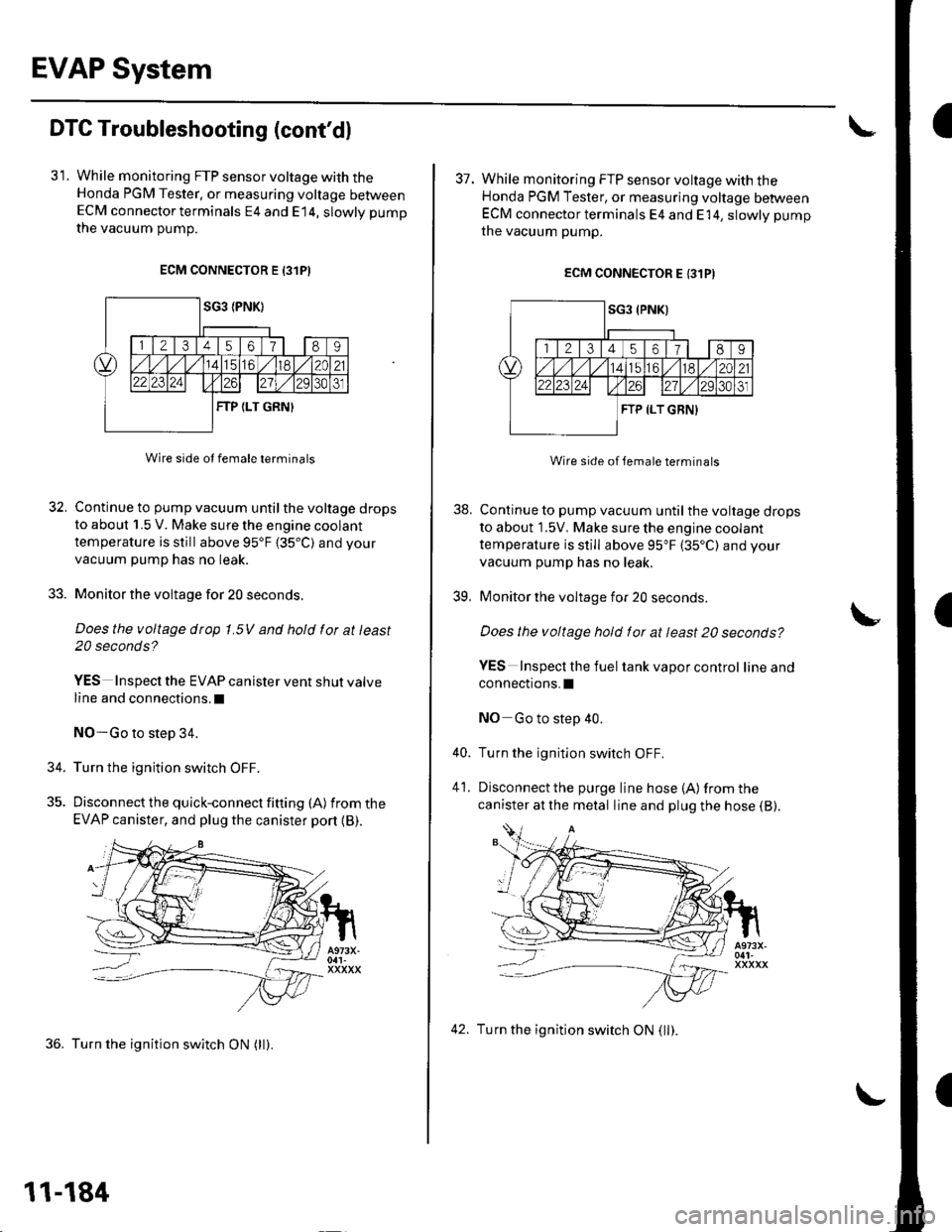
31. While monitoring FTP sensor voltage with theHonda PGM Tester, or measuring voltage betweenECM connector terminals E4 and E14, slowly pump
the vacuum oumD.
ECM CONNECTOR E 13lPI
Wire side ot female terminals
32. Continue to pump vacuum until the voltage drops
to about 1.5 V. Make sure the engine coolant
temperature is still above 95'F 135.C) and your
vacuum pump has no leak.
33. Monitor the voltage for 20 seconds.
Does the voltage drop 1.5V and hold for at least
20 seconds?
YES Inspect the EVAP canister vent shut valve
line and connections.l
NO-Go to step 34.
34. Turn the ignition switch OFF.
35. Discon nect the quick-con nect fitting (A) fromthe
EVAP canister, and plug the canister port {B).
36. Turn the ignition switch ON (ll).
11-184
42. Turn the ignition switch ON (ll).
I
38.
39.
37. While monitoring FTP sensor voltage with theHonda PGM Tester, or measuring voltage betweenECM connector terminals E4 and E 14, slowly pump
the vacuum pump.
ECM CONNECTOR E {31PI
Wire side of lemale terminals
Continue to pump vacuum until the voltage drops
to about 1.5V. Make sure the engine coolant
temperature is still above 95"F (35"C) and your
vacuum pump has no leak.
Monitor the voltage for 20 seconds
Does the voltage hold for at least 20 seconds?
YES Inspecl the fuel tank vapor control lineand
connections.I
NO Go to step 40.
Turn the ignition switch OFF.
Disconnect the purge line hose {A) from the
canister at the metal line and plug the hose (B).
40.
41.
Page 392 of 1139
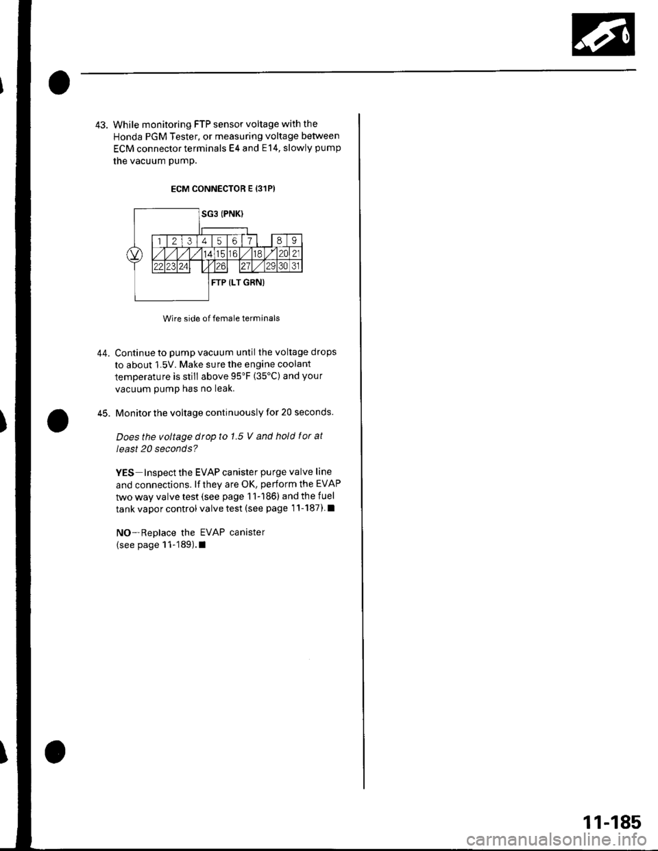
43. While monitoring FTP sensor voltage with the
Honda PGM Tester, or measuring voltage between
ECM connector terminals E4 and E14, slowly pump
the vacuum pump.
ECM CONNECTOR E {31P)
Wire side of female terminals
Continue to pump vacuum until the voltage drops
to about 1.5V. Make sure the engine coolant
temperature is still above 95'F (35'C) and your
vacuum pump has no leak.
Monitor the voltage continuously for 20 seconds.
Does the voltage drop to 1.5 V and hold f or at
least 20 seconds?
YES Inspect the EVAP canister purge valve line
and connections. lf they are OK, perform the EVAP
two way valve test (see page 11-186) and the fuel
tank vapor control valve test (see page 1'l-187) l
NO-Replace the EVAP canister
(see page 11-189).1
44.
45.
11-185
Page 394 of 1139
FuelTank Vapor Control Valve Test
Special Tools Required
Vacuum Pump/Gauge, 0-30 in. Hg A973X-041-XXXXX
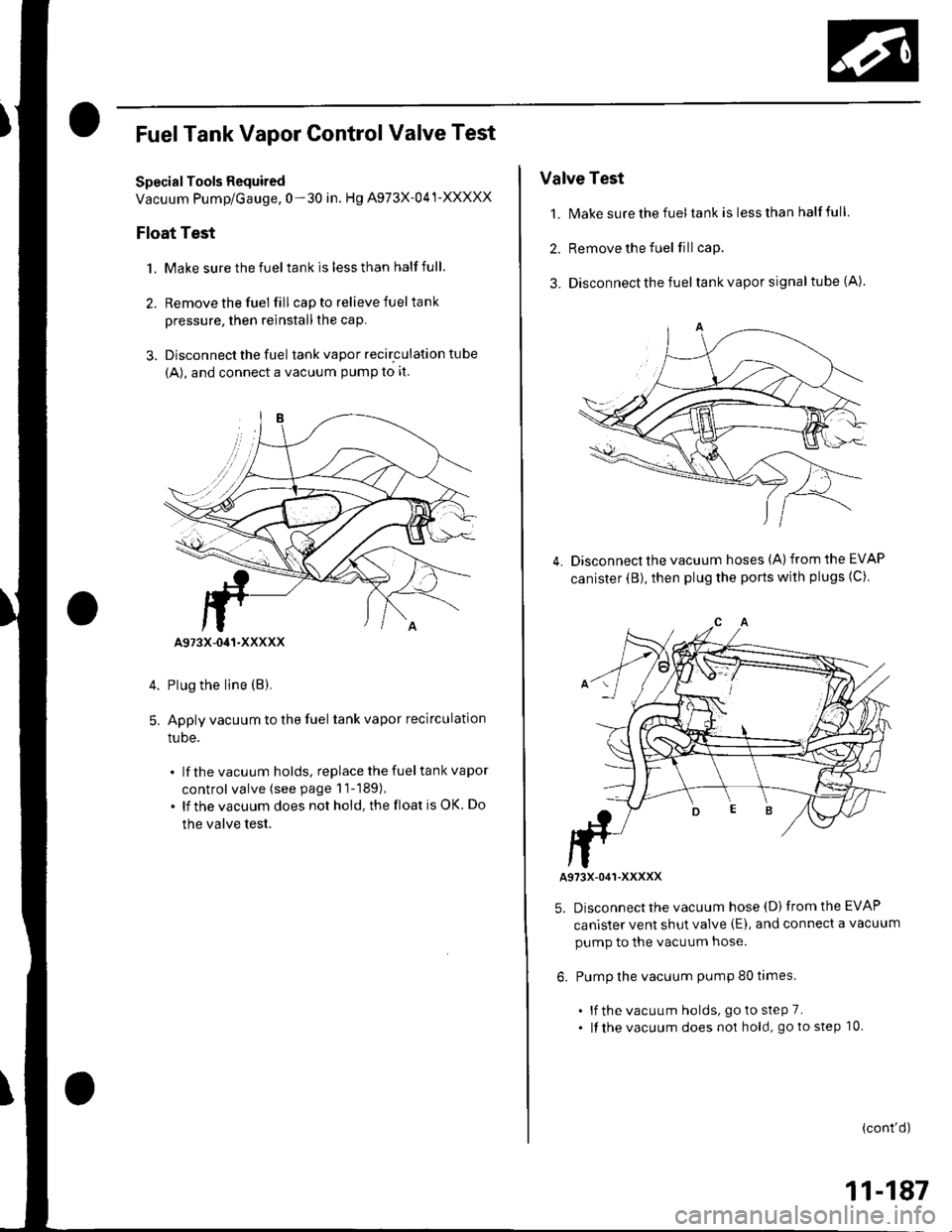
Float Test
1. Make sure the fuel tank is less than half full.
2. Remove the fuel fill cap to relieve fuel tank
pressure, then reinstall the cap.
3. Disconnect the fuel tank vapor recirculation tube
{A), and connect a vacuum PumP to it.
Plug the line (B).
Apply vacuum to the fuel tank vapor recirculation
tuDe.
lf the vacuum holds, replace the fuel tank vapor
control valve (see page 11-189).
lf the vacuum does not hold, the float is OK. Do
the valve test.
5.
A973X-041-XXXXX
Valve Test
1. N4ake sure the fuel tank is less than half full
2. Remove the fuel fill cap.
3. Disconnect the fuel tank vapor signal tube (A).
Disconnect the vacuum hoses (A) from the EVAP
canister (B), then plug the ports with plugs (C)4.
A973X-O41-XXXXX
5. Disconnect the vacuum hose (D) from the EVAP
canister vent shut valve (E), and connect a vacuum
pump to the vacuum hose.
6. Pump the vacuum pump 80 times.
. lf the vacuum holds, goto steP 7.. lf the vacuum does no1 hold, go to step 10.
(cont'd)
11-187
Page 395 of 1139
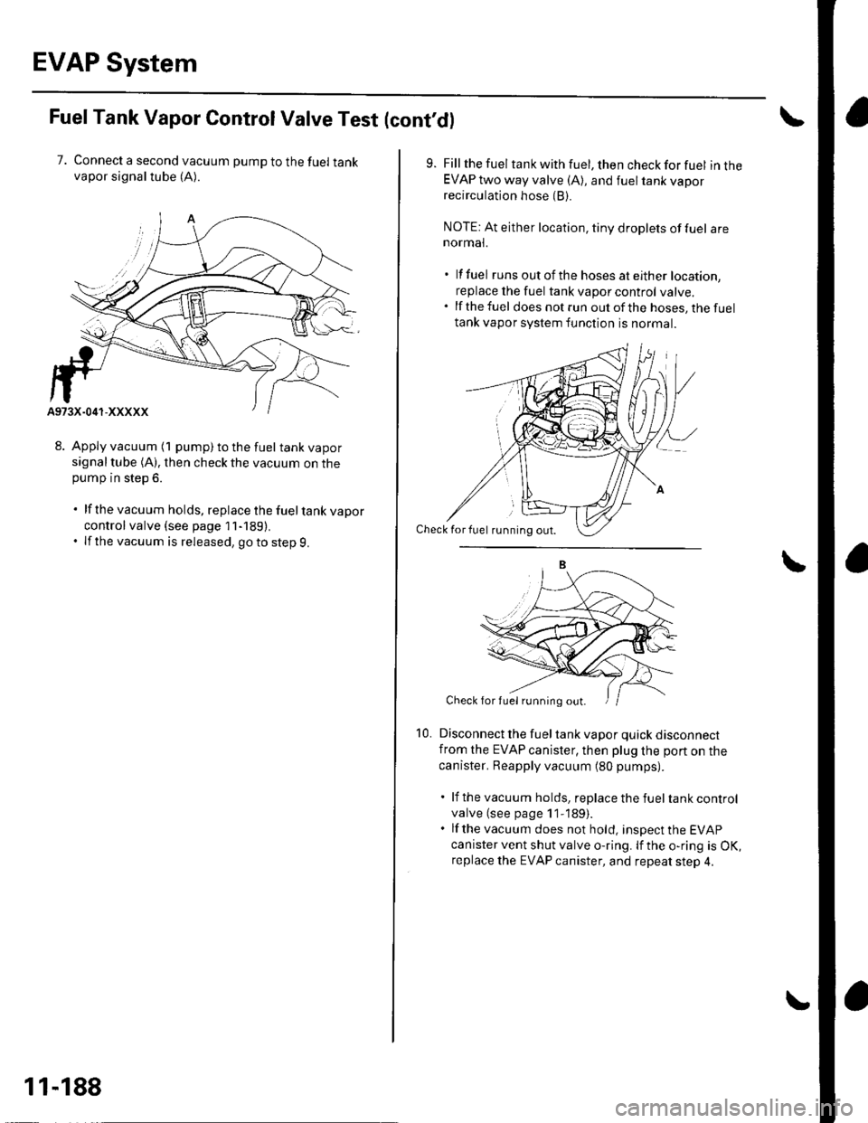
EVAP System
FuelTank Vapor ControlValve Test (cont'd)
7. Connect a second vacuum pump to the fuel tankvapor signaltube (A).
8. Apply vacuum (1 pump) to the fuel tank vaporsignal tube (A). then check the vacuum on thepump in step 6.
. lf the vacuum holds, replace the fueltank vapor
control valve {see page 11-189).. If the vacuum is released, goto step 9.
11-188
10.
Fill the fuel tank with fuel, then check for fuel in theEVAP two way valve (A), and fuel tank vaporrecirculation hose (B).
NOTE: At either location, tiny droplets of fuel arenormal.
. lf fuel runs out of th e hoses at either location,
replace the fuel tank vapor control valve..lfthefuel does not run out of the hoses, the fuel
tank vapor system function is normal.
Disconnect the fuel tank vapor quick disconnectfrom the EVAP canister, then plug lhe port on the
canister. Reapply vacuum (80 pumps).
. lf the vacuum holds, replace the fuel tank control
valve (see page 1 1-189).. lf the vacuum does not hold, insDect the EVAP
canister vent shut valve o-ring. lf the o-ring is OK,replace the EVAP canister, and repeat step 4.
Check for fuel rirnning out.
Check for fuel running out.
Page 396 of 1139
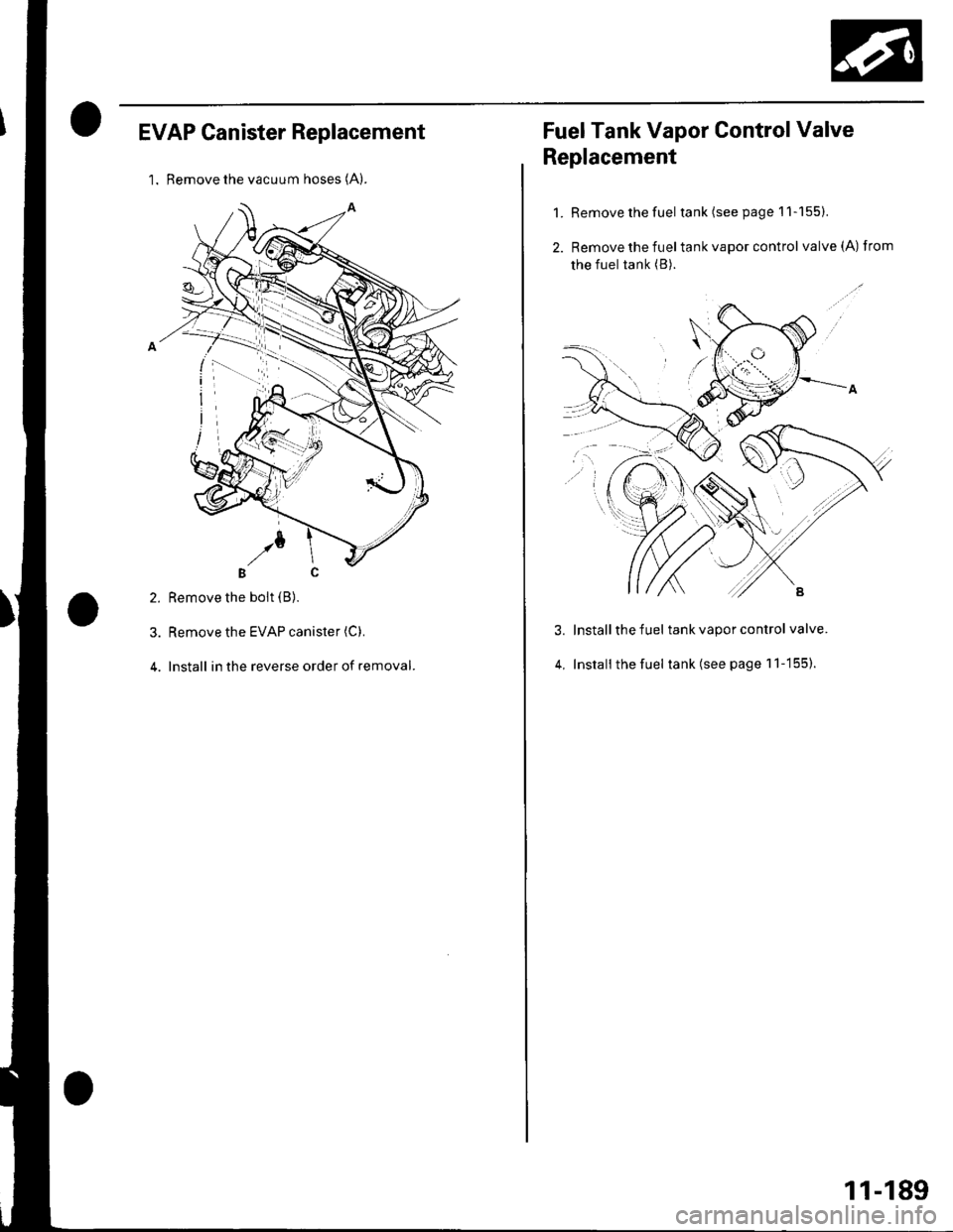
EVAP Canister Replacement
l. Remove the vacuum hoses (A).
2. Remove the boit (B).
3. Remove the EVAP canister (C).
4. Install in the reverse order of removal.
Fuel Tank Vapor Control Valve
Replacement
1. Remove the fuel tank(seepagell-155).
2. Remove the fueltank vapor control valve(A) from
the fuel tank (B).
Install the fuel tank vapor control valve.
Install the fuel tank (see page 1 'l -155).
3.
4,
11-189
Page 847 of 1139
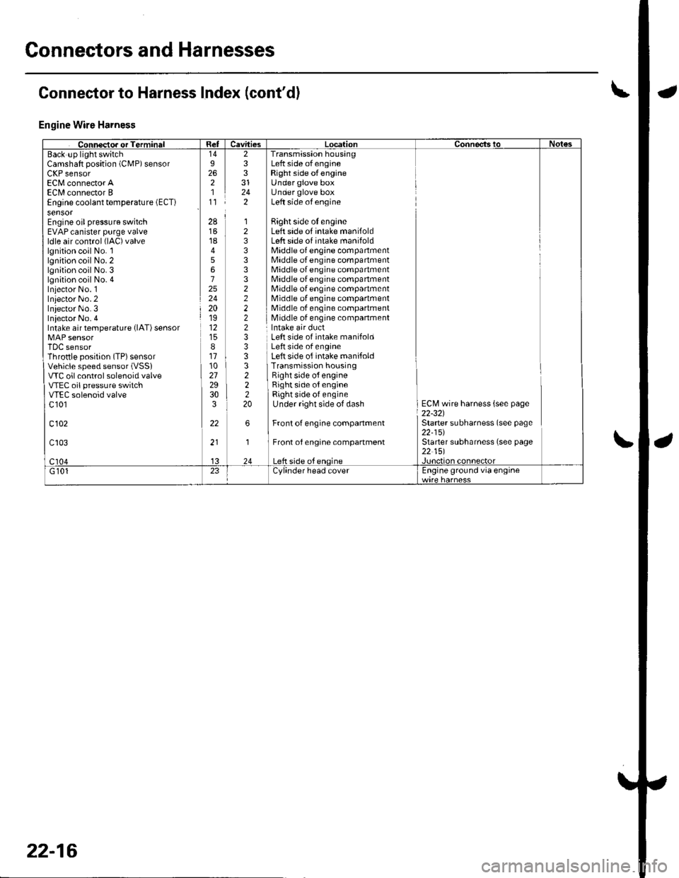
Connectors and Harnesses
Engine Wire Harness
Camshaft position (CMP) sensorLllr sensorEC[,4 connector AECI/l connector BEngine coolant temperature (ECT)
sensorEngine oil pressure switchEVAP canister purge valveldle air control (lAC)valve
lgnition coil No. llgnition coil No. 2lgnition coil No. 3lgnition coil No. 4Iniector No. 1Inlector No.2Iniector No.3Iniector No. 4Intake air temperature {lAT) sensor
TDC sensorThrottle position (TP) sensorVehicle speed sensor (VSSI
VTC oil control solenoid valveVTEC oil pressure switchVTEC solenoid valvec 101
c102
233
242
Transmission housingLeft side of engineRight side ofengineUnder glove boxUnder glove boxLeft side of engine
Bight side oI engineLeft side of intake manifoldLeft side of intake manifoldMiddle of engine compartmentMiddle of engine compartmentMiddle of engine compartmentMiddle of engine compartmentMiddle of engine compartmentMiddle of engine compartmentMiddle of engine compartmentMiddle of engine companment
28
1845672524201912
811102729303
22
12333332222233
322220
Left side of intake manifoldLeft side of engineLeft side of intake manifoldTransmission housingRight side o{ engineRight side of engineRight side of engineUnder right side of dash
Front of engine companment
Front of engine compartment
ECM wire harness {see page22-321Starter subharness (see page22-15)Starter subharness (see page22 151
Connector to Harness Index (cont'dl
22-16
Page 867 of 1139
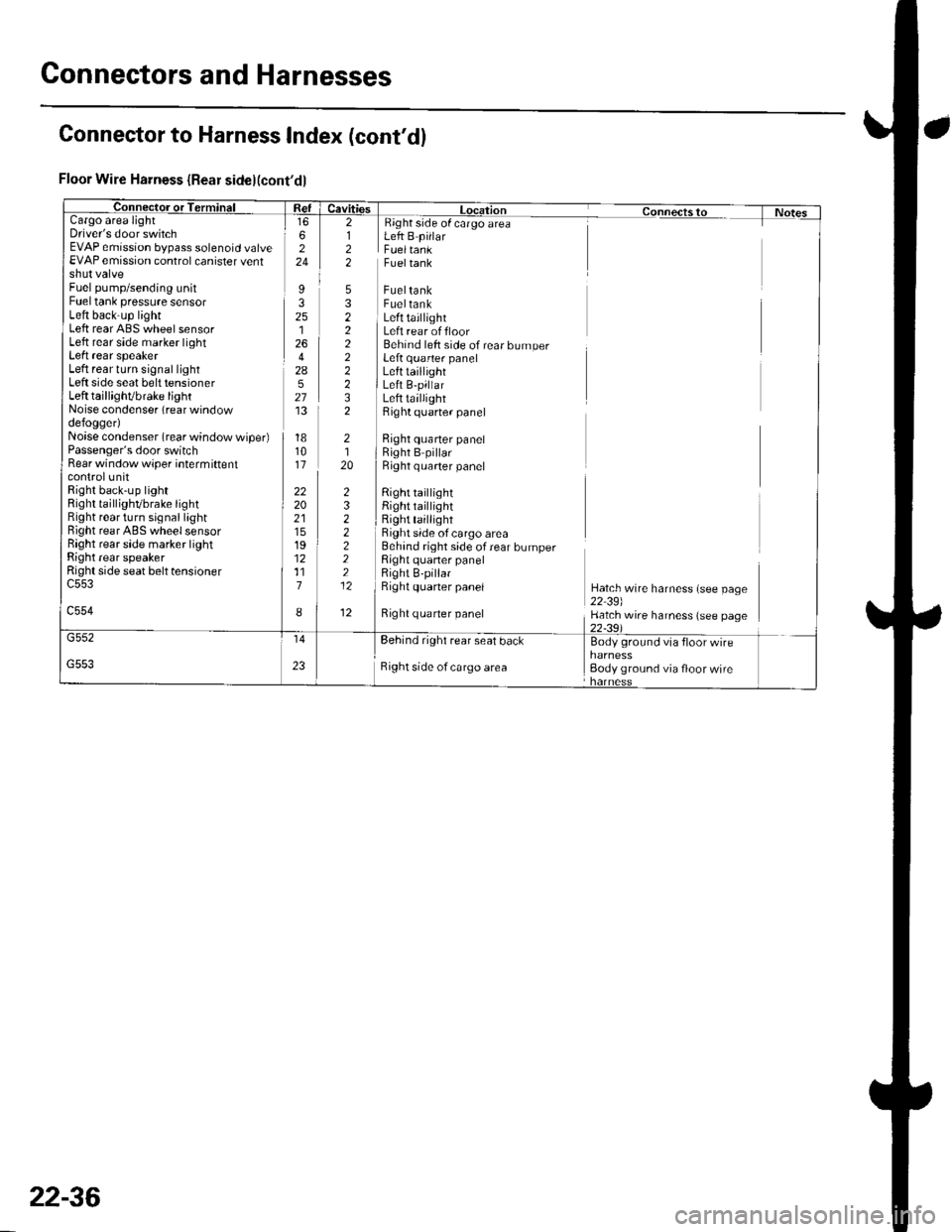
Gonnectors and Harnesses
a
Floor Wire Harness {Rear side}(cont'dl
Cargo areaDriver's door switchEVAP emission bypass solenoid valveEVAP emission control canister ventshut valveFuel pump/sending unitFuel tank pressure sensorLeft back-up lightLeft rear ABS wheel sensorLeft rear side marker lightLeft rear speakerLeft rear turn signal lightLeft side seat belt tensionerLeft taillighVbrake lightNoise condenser (rear windowdefogger)Noise condenser (rear window wiper)Passenger's door switchRear window wiper intermiftentcontrolunitRight back-up lightRight taillighvbrake tightRight rear turn signal lightBight rear ABS wheel sensorRight rear side marker lightRight rear speakerRight side seat belt tensioner
c554
Fueltank
FueltankFueltankLeft taillightLeft rear offloorBehind left side of rear bumperLeft quarter panelLefttaillightLeft B-pillarLeft taillightRight quarter panel
Right quarter panelRight B pillarRight q uarter panel
Right tai ightRight taillightRight taillightRight side of cargo area
side of cargo areaLeft B pillarFueltank
Right quaner panel
6224
I32512642A527'13
181011
222021151912117
I
2122
5322222232
232222212
12
2120
Behind right side of rear bumperRight quaner panelRight B-pillarRight quaner panelHatch wire harness (see page22 39)Hatch wire harness (see page
rear seal bdcl Bodv ground vta
Right side of cargo area Body ground via floor wire
Connector to Harness Index (cont'dl
22-36
Page 878 of 1139
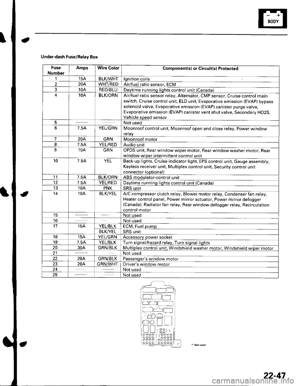
Under-dash Fuse/Relay Box
Fuse
Number
AmpsWire ColorComponent(s) or Circuit(s) Protected
115ABLKA/VHTlgnition coils
2204WHT/REDAirlfuel ratio sensor, ECM
310ARED/BLUDaytime running Iights control unit {Canada)10ABLI(ORNAir/fuel ratio sensor relay, Alternator, CMP sensor, Cruise control main
switch, Cruise control unit. ELD unit, Evaporative emission (EVAP) bypass
solenoid valve, Evaporative emission (EVAP)canister purge valve,
Evaporative emission (EVAP) canister vent shut valve, Secondary H02S,
Vehicle speed sensor
5Not used
67.5AYEUGRNMoonroof control unit, Moonroof open and close relay, Power window
relaV
7204GRNMoonroof motor
I7.5AYEUREDAudio unit
910AGRNOPDS unit, Rear window wiper motor, Rear window washer motor, Rear
window wiper intermittent control unit
107.54YELBack-up lights, Cruise indicator light, EPS control unit, Gauge assembly,
Keyless receiver unit, Multiplex control unit, Security control unit
connector (optional)
117.5ABLIVORNABS modulator-control unit
127.5AYEUREDDaytime runnino liohts control unit (Canada)
1310APNKSRS unit't410ABLK/YE LA,,/C compressor clutch relay, Blower motor relay, Condenser fan relay,
Heater control panel, Power mirror actuator, Power mirror defogger(Canada), Radiator fan relay, Rear window defogger relay, Recirculation
control motor1ENot used
loNot used
1715AYE L/B LKECM, Fuel pump
B LK/YE L>H> Unrr
1815AYEUGRNAccessory power socket
197.5AYEUBLKTurn siqnal/hazard relav, Turn siqnal liohts
2030AGRN/BLKMultiplex control unit, Windshield washer motor. Windshield wioer motor21Not used
22204GRN/BLKPassenqer's window motor
2320A.G R N,A/VHTDriver's window motor
24Not used
25Not used
__^:Hr tl_l
f at-t
at I
r^,rl fl
!!;r -
!339,i;s!!sf Fnf : |rnITf
22-47
Page 1135 of 1139
)
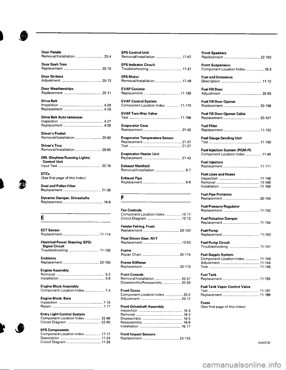
Orive BehInspecaron................ 4-26
Door PanelsRemoval/lnstallation -............................. 20-4
Door Sash TrimRep1acement......................................... 20 10
Door StrikersAdiustment ........................................... 20-13
Door Weatherst psBeplacement...........-............................. 20 1 1
EPS Conirol UnitRemoval/1nsta11ation ..................-......... 17-67
EPS Indicator CircuitTroubleshooting ................................... 17 -47
EPS MotorRemoval/lnstallation .-.......................... 17-49
EVAP CanisterRep1acement......................... ......... 11,189
EVAP Control Syst€mComponentLocation Index ..............'11-170
EVAP Two-Wey ValveTest ..........-.............-............................ 11 186
Evaporetor CoreRep1acement........................ . ... 21-42
Evaporator Tomperature SensorReplacement......................................... 21 -37Test..................................... ..........2137
EvaporrtoFHeater UnitReplacement........................................ 21 43
Exhaust ManifoldRemoval/1nsta11ation ................................ I 7
Exhaust Pipe8ep|acement............................................. 9-8
Front SpeakersRep|acement....................................... 22-102
Front SuspensionComponentLocation Index................... 18-3
Fueland EmissionsDescription ........................................... 11-12
Fuel Fill DoorAdjustment ..........-................................ 20 93
Fuel Fill Door OpenetBeplacement........................ . ............ 20.109
Fuel Fill Door Opener CableReplacement....................................... 20- lO7
Fuel FilterReplacement....................................... 1 1-152
Fuel Gauge Sending UnitTest ......................-.-..........-.................. 11'156
Fuel Injection Syslem (PGM"FIlComponent Location 1ndex................. 11-49
Fuel IniectorsRep1acemen1....................................... 1 1 1 1 l
Fuel Lines and HosesInspection .......................................... 1 1'146Removal ....................... . .. . .... 11-149Insta|1ation .......................................... 1 1 150
FuelPipe ProtectolReplacement....................................... 20-104
Fuel Pressure RegulatotReplacement....................................... 1 1-152
Fuel Pulsation DamperReplacemenl................................... 11 154
Fuel PumpReplacement,,,,,.,.,.,,,.,,,,,,,,,,,,.,.,.,,,..,.. 11-153
Fuel Pump CircuitTroubleshooting -.......-....................... 1 1-141
FuelSupply SystemComponent Location lndex .............. 11 140Adjustment................................... 11-144Test........-...-................. ... ............- 11-145
FuelTankBeplacemenl.............. . ..... .. 11 155
Fuel Tank Vapor ControlValveTest ......................-....... ... . . 11-187Replacement,,.,,...,.,,,.,.,,,,... .. .. 11 189
Fuses{See first page ofthis Index)
)
Rep|acement................. ..................... 4 26
Drive Belt Auto-tensionellnspection ............................................... 4 21Rep1acement.................................... ..4-28
Driver's PocketRemoval/lnstallation -........................... 20-60
Driver's TrayRemoval/lnstallation .........................-.- 20-65
DRL {Daytime Running LightslControl Unitlnput Test .................... ........ . . . ......22-16
DTCs(See first page olthis Index)
Dust and Pollen FillerReplacement......................................... 21-39
Dynamic Damper, DriveshaftsReplacement........................................... 16-8
ECT SensorReplacement.,.,,,.,.,,,,,,,,,,,,,,................ 1 1-1 14
El€ctrical Power Steering IEPS)Signal CircuitTroubleshooting ........ ... .. 11-135
EmblemsReplacement......................-................ 20-100
Engine AssemblyRemova1 .................................................... 5 2Installation ............._.................................. 5-9
Engine Block AssemblyComponent Location Inder ..................... 7.3
Engine Block, BareInspect|onRepair
Fan ControlsComponent Location Index................. 10'l 1Circuit Diagram .. ..... . .. . .................. 10 13
Fender Fairing, FrontReplacement...-................................... 20-103
Final Driven Gear. M/TReplacement.... . . ................................ 13-53
FrameRepair Chan............ ... ....................... 20 11 4
Frame StiffenelReplacement......-................................ 20- J'13
Front ConsoleRemoval/lnstallation ............................ 20 5lDisassembJy/Reassemb|y ................... 20 58
Front DoorsComponent Location Index................... 20-2Adiustment ........................................... 20.12
Front Driveshaft AssemblyInspeclion .................... ... ....16 3Remova1...................-...... ... .....16-3Disassembly ............................... .....165Resassemb|y ................................-......... 16-9Insta11arion ........................ ...... ............ l6 17
Front lmpact SensorsRep1acement............................ ...23 125
................7-15................1 11
)
Entry Light Control SystemComponent Location Index ...............-. 22-89Circuit Dia9ram .................................... 22 90
EPS ComponentsComponent Location 1ndex..........-...... 17-!7Description ........................ ...... ..17-24Circuit Diagram11 26(cont'd)