head HONDA CIVIC 2002 7.G Repair Manual
[x] Cancel search | Manufacturer: HONDA, Model Year: 2002, Model line: CIVIC, Model: HONDA CIVIC 2002 7.GPages: 1139, PDF Size: 28.19 MB
Page 165 of 1139
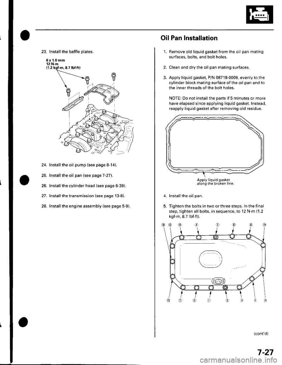
23. Install the baffle plates.
6x1.0mm12 N.m(1.2 ksf m, 8.7 lbf ft)
24. Installthe oil pump (see page 8-14).
25. Installthe oil pan (see page 7-27).
26. Installthe cylinder head (see page 6-39).
27. Installthe transmission (see page 13-8).
28. Installthe engine assembly (see page 5-9).
1.
OilPan lnstallation
Remove old liquid gasket from the oil pan mating
surfaces, bolts, and bolt holes.
Clean and dry the oil pan mating surfaces.
Apply liquid gasket, P/N 08718-0009, evenly to the
cylinder block mating surface of the oil pan and to
the inner threads of the bolt holes.
NOTE: Do not install the parts if 5 minutes or more
have elapsed since applying liquid gasket. Instead,
reapply liquid gasket after removing old residue.
Installthe oil pan.
Tighten the bolts in two or three steps. In the final
step, tighten all bolts, in sequence, to 12 N.m (1.2
kgf m, 8.7 lbf.ft).
(cont'd)
2.
3.
4.
5.
Apply liquid gasketalong the broken line.
(}@
7-27
Page 166 of 1139
Engine Block
Oil Pan Installation (cont'dl
6. lf the engine is still in the vehicle, install the
subframe,
-1 Installthe subframe. Align the reference lines
on the subframe with the bolt head center, then
tighten the bolts (see step 5 on page 5-10).-2 Tighten the front mounting bolt (see step 6 onpage 5-10).-3 Tighten the rear mount mounting bolts (see
step 7 on page 5-11).-4 Connect the suspension lower arm ball joints
(see step 6 on page 18-19).
7. After assembly, wait at least 30 minutes before
filling the engine with oil.
7-28
v
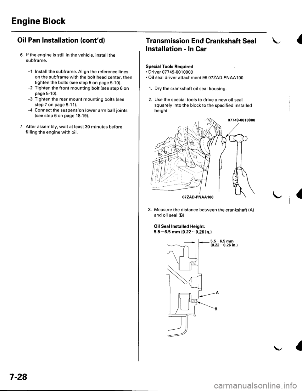
Transmission End Grankshaft Seal
Installation - In Car
Special Tools Required. Driver 07749-0010000. Oil seal driver attach ment 96 07ZAD-PNAA100
'1. Dry the crankshaft oil seal housing.
2. Use the special tools to drive a new oil seal
squarely into the block to the specified installed
height.
07749-0010000
and oil seal (B).
Oil Seal Installed Height:
5.5 6.5 mm 10.22-0.26 in.l
5.5 6.5 mml0.22- O.26 in .l
I
/$rRfr4T
tr*W(r
-]t
fl\OTZAD.PNAAlOO
Measure the distance between the crankshaft (A)
a
Page 200 of 1139
Cooling System
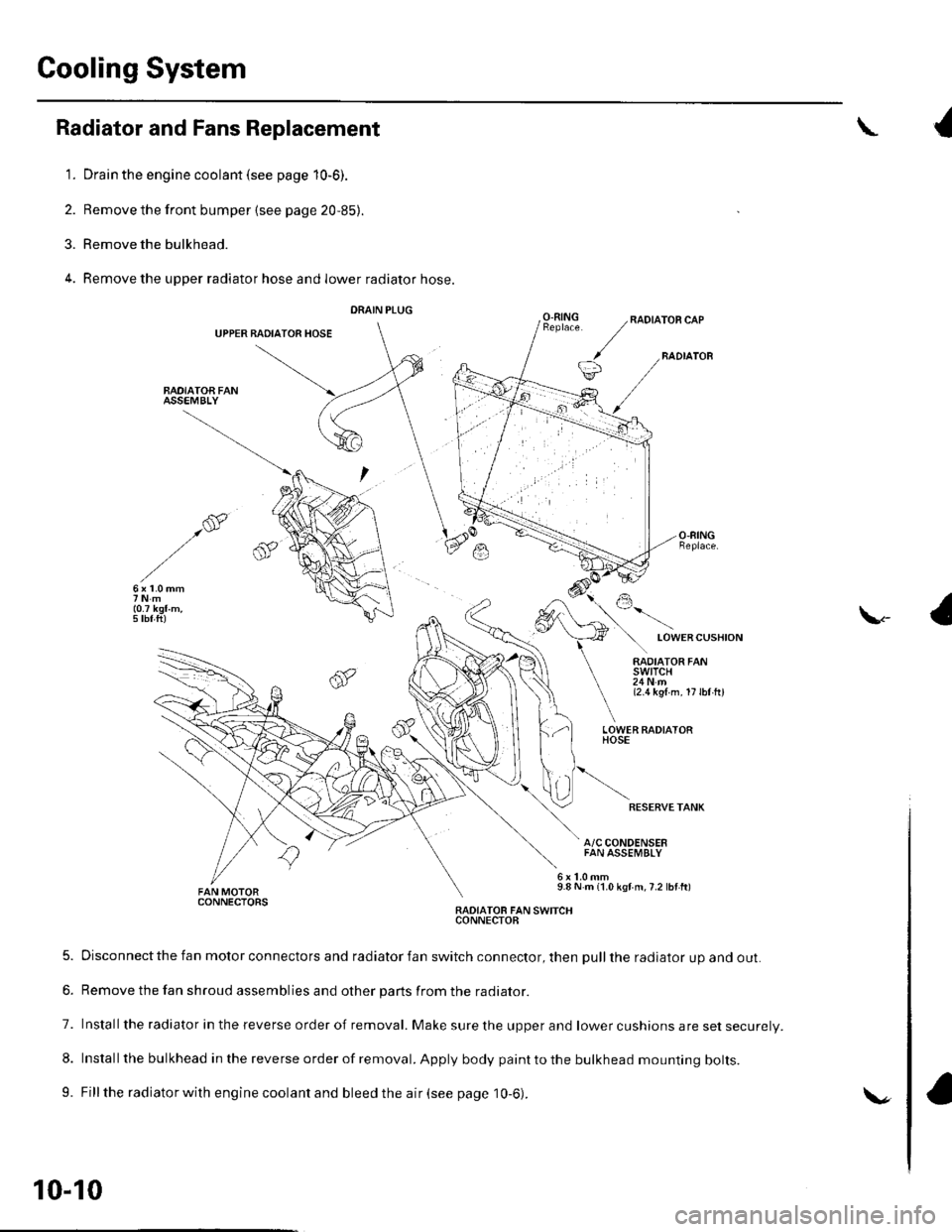
Radiator and Fans Replacement
1. Drain the engine coolant (see page 10-6).
2. Remove the front bumper {see page 20,85).
3. Remove the bulkhead.
4. Remove the upper radiator hose and lower radiator hose.
DRAIN PLUG
UPPER BADIATOR HOSE
BAOIATOA FANASSEMBLY
{
O.RINGRADIATOR CAP
BADIATOB
LOWERCUSHION
\-
RADIATOR FANswtTcH24Nm{2.1t kgl m. 17lbl hl
LOWER FADIATORHOSE
RESERVETANK
A/C CONDENSERFAN ASSEMBLY
9.8 N m {1.0 kgf m,7.2 lbf ft)CONNECTORSRADIATOB FAN SWITCHCONNECTOB
5. Disconnect the fan motor connectors and radiator fan switch connector, then pull the radiator up and out.
6. Remove the fan shroud assemblies and other parts from the radiator.
7. Installthe radiator in the reverse order of removal. Make sure the upper and lower cushions are set securelV.
8. Install the bulkhead in the reverse order of removal. Apply body paint to the bulkhead mounting bolts.
9. Fill the radiator with engine coolant and bleed the air (see page 10-6).
10-10
\.
Page 229 of 1139
![HONDA CIVIC 2002 7.G Repair Manual Fuel and Emissions Systems
System Descriptions (contdl
ECM lnputs and Outputs at Connector E (31P}
L
u
1iMoFPR
2sr-{]zs3LG34SG3
6$1025HTC
1M RLY
8AFSHTCR
I
14FTP15ELD
16EPSLD
18ACC20Z/VBS21VSV
22BKSW HONDA CIVIC 2002 7.G Repair Manual Fuel and Emissions Systems
System Descriptions (contdl
ECM lnputs and Outputs at Connector E (31P}
L
u
1iMoFPR
2sr-{]zs3LG34SG3
6$1025HTC
1M RLY
8AFSHTCR
I
14FTP15ELD
16EPSLD
18ACC20Z/VBS21VSV
22BKSW](/img/13/5744/w960_5744-228.png)
Fuel and Emissions Systems
System Descriptions (cont'dl
ECM lnputs and Outputs at Connector E (31P}
L
u
1iMoFPR
2sr-{]zs3LG34SG3
6$1025HTC
1M RLY
8AFSHTCR
I
14FTP15ELD
16EPSLD
18ACC20Z/VBS21VSV
22BKSW23K-LINE24SEFMJ26NEP
21rMoCD
29scs30WEN31MIL
Wire side of female terminals
NOTE: Standard battery voltage is '12 V.
TerminalnumberWire colorferminal nameDescription Signal
GRNI/ELIMO FPR (IMMOBILIZERFLJEL PUMP RELAYIDrives PGM Fl main relay 20Vfor2 seconds after turning ignition switch ON{ll). then batterv voltaoe2WHT/REDSHO2S (SECONDARYHEATED OXYGEN SENSOR(SECONDARY HO2S),SENSOR 2r
Detects secondary HO2S{sensor 2) signalWith throttle Jully opened from idle with fullywarmed up engine: above 0.6VWith throttle quickly closed: below 0.4 V
3BRN/YELLG3 (LOGIC GROUND)cround forthe ECM/PCMcontrolcircuitLess than 1.0 V at all times
4PNKSG3 {SENSOR GBOUND)Sensor oroundLess than 1.0 V at all times5YEUELUVCC3 {SENSOR VOLTAGE)Provides sensor voltageWith ignition switch ON (ll): about 5 VWith ionition switch OFF: about 0 V6BLKATr'HTSO25HTC (SECONDARYHEATED OXYGEN SENSOR(SECONDARY H02S)HEATER CONTROL)
Drives secondary HO2SheaterWith ignition switch ON (ll): baftery voltageWilh fullv warmed up engine running: dul,controlled
1REDA/ELMRLY (PGM.FI MAINRELAY}Drives PGM-Flmain relay 1Power source forthe DTCWith ignition switch ON (ll): about 0 VWith ignition switch OFF: battery voltage
IORNAFSHTCR {AIR FUEL BATIO(Iy'F)SENSOR HEATERCONTROL RELAY)
Drives air fuel ratio sensorheater relayWith ignition swirch ON {ll): 0 V
IYEUBLKIGl (IGNITION SIGNAL)Detecrs ignition signalWith ignition switch ON (ll): battery voltageWith iqnition switch OFF: about 0 V't4LT GRNFIP lFUEL TANKPRESSURE (FTP) SENSOR)Detects FTP sensor signalWith ignition switch ON (ll) and fuel fill cap open:about 2.5 VGRN/REDELD (ELECTRICAL LOADDETECTOF)Detects ELD signalWith ignition swjtch ON itt):aOoutO.t V l-gV(deDendino on electrical load)LT GRN/8LKEPSLD (ELECIRICALPOWEB STEEBING LOADDETECT)
Detects Power steering loadsrgnalAt idle with steering wheel in straight aheadposition: about 0 VAt idle with steering wheelatfull lock: momentary
'18REDACC (Ay'C CLUTCH RELAY)Drives P,/C clutch relayWith compressor ON: about 0 VWith comoressor OFF: batterv voltaoe
11-22
\-
Page 240 of 1139
Intake Air System
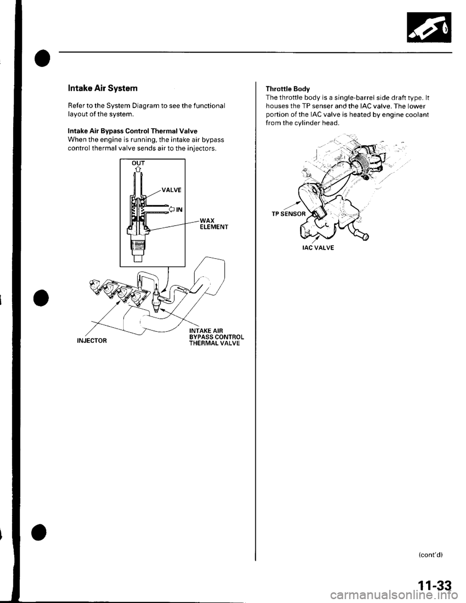
Refer to the System Diagram to see the functional
layout of the system.
Intake Air Bypass Control Thermal Valve
When the engine is running, the intake air bypass
control thermal valve sends air to the iniectors,
INJECTOR
Throttle Body
The throttle body is a single-barrel side draft type. lt
houses the TP senser and the IAC valve. The lower
portion of the IAC valve is heated by engine coolant
from the cylinder head.
IAC VALVE
{cont'd)
11-33
Page 299 of 1139
PGM-FI System
I
a
DTC Troubleshooting (cont'dl
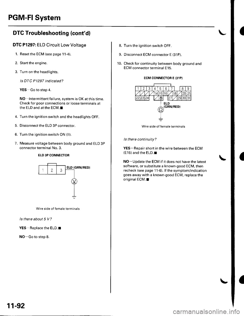
DTC Pl297: ELD Circuit Low Voltage
1. Reset the ECM {see page 11-4).
2. Start the engine.
3. Turn on the headlights.
ls DTC P1297 indicated?
YES Go to step 4.
NO Intermittent failure, system is OK at this time.
Check for poor connections or loose terminals at
the ELD and at the ECM.I
4. Turn the ignition switch and the headlights OFF.
5. Disconnectthe ELD 3P connector.
6. Turn the ignition switch ON {ll).
7. Measure voltage between body ground and ELD 3P
connector terminal No. 3.
ELO 3P CONNECTOB
{GRN/REDI
Wire side of female terminals
ls there about 5 V?
YES Replace the ELD. t
NO-Go to step 8.
Z3ELD
11-92
8. Turn the ignition switch OFF.
9. Disconnect ECM connector E {31P).
10. Check for continuity between body ground and
ECM connector terminal E15.
ECM CONNECTOR E 131PI
I l2l3456178I
totd/ 12021,2 2al2/tA31
ELD(GRN/RED}7\'
Wire side of female terminals
ls there continuity?
YES-Repair short in the wire between the ECM(E 15) and the ELD. r
NO- U pdate the ECM if it does not have the latest
software, or substitute a known-good ECM, then
recheck (see page 1 1-6). lf the symptom/indication
goes away with a known-good ECM, replace the
original ECM.I
Page 300 of 1139
DTC Pl298: ELD Circuit High Voltage
1. Resetthe ECM (see page 11-4)
2. Stan the engine.
3. Turn on the headlights.
ls DTC P1298 indicated?
YES-Go to step 4.
NO- Intermittent failure. system is OK at this time.
Check for poor connections or loose terminals at
the ELD and at the ECM.I
4. Turn the ignition switch and headlights OFF.
5. Disconnectthe ELD 3P connector.
6. Turn the ignition switch ON (ll).
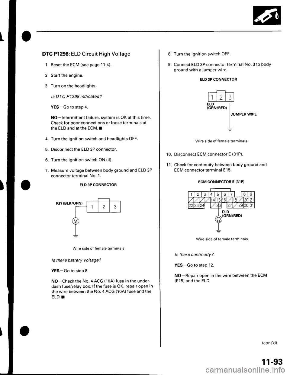
7. Measure voltage between body ground and ELD 3P
connector terminal No. 1.
ELD 3P CONNECTOR
IG1 IBLK/ORNI
Wire side ot {emale terminals
ls there battery voltage?
YES-Go to step 8.
NO-Checkthe No. 4 ACG (10A)fuse in the under-
dash fuse/relay box. lf the fuse is OK, repair open in
the wire between the No. 4 ACG (10A) fuse and the
ELD.I
8.
9.
10.
11.
Turn the ignition switch OFF.
Connect ELD 3P connector terminal No. 3 to body
ground with a jumper wire.
Disconnect ECM connector E (31P).
Check for continuity between body ground and
ECM connector terminal E15.
ECM CONNECTOR E 131PI
1 21345ot/II
14LC6l/ 182C21
22123 2421 ./2Q30J
ELDIGRN/RED)i1'
Wire side of female terminals
Is thete continuity?
YES-Go to step 12.
NO Repair open in the wire between the ECM
(E15) and the ELD.
(cont'd)
ELD 3P CONNECTOR
---F-------
l1l2 :rlELD(GRN/RED)
IJUMPER wrRE
II
Wire side of temale terminals
11-93
Page 301 of 1139
PGM-FI System
DTC Troubleshooting (cont'dl
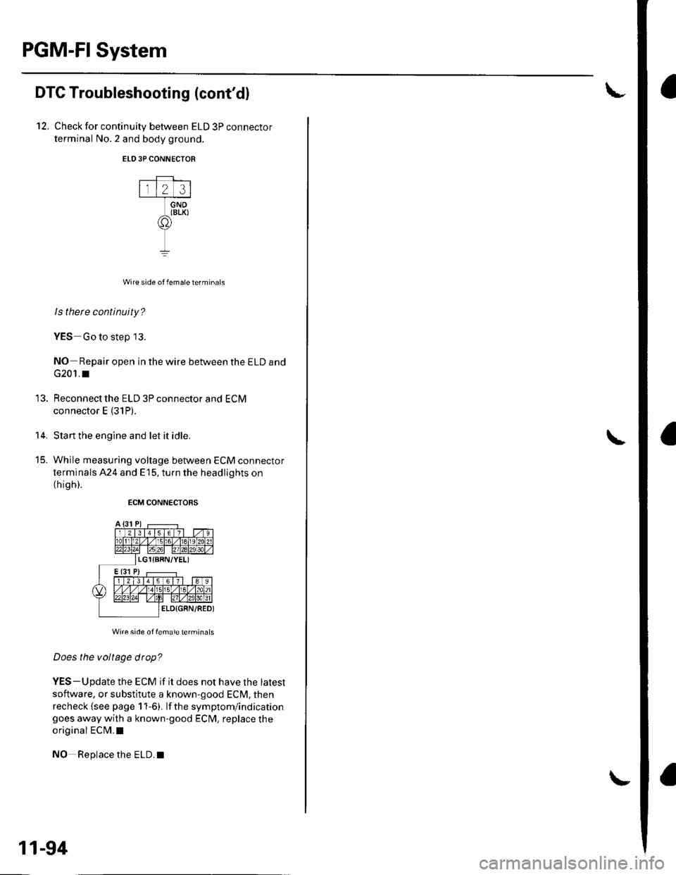
12, Check for continuity between ELD 3P connector
terminal No.2 and body ground.
ELD3P CONNECTOR
Wire side of female terminals
ls there continuity?
YES Go to step 13.
NO- Repair open in the wire between the ELD and
G201. I
Reconnect the ELD 3P connector and ECM
connector E (31P).
Start the engine and let it idle.
While measuring voltage between ECM connector
terminals 424 and E15, turn the headlights on
th igh).
ECM CONNECTORS
Wi.e side of female terminals
Does the voltage drop?
YES-Update the ECM if it does not have the latest
software, or substitute a known-good ECM, then
recheck {see page 1 1-6). lf the symptom/indicationgoes away with a known-good ECM, replace the
original ECM.I
NO Replace the ELD.I
14.
t5_
11-94
Page 329 of 1139
VTEC/VTC
10.
DTC Troubleshooting (cont'd)
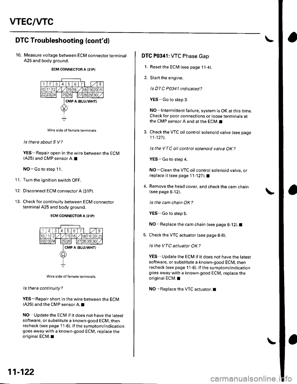
Measure voltage between ECM connector terminal
A25 and body ground.
ECM CONNECTOR A 131P)
Wire side of female te.minals
ls there about 5 V?
YES-Repair open in the wire between the ECM(A25) and CMP sensor A.I
NO-Go to step 11.
Turn the ignition switch OFF.
Disconnect ECM connector A (31P)
Check for continuity between ECM connecror
terminal A25 and body ground.
ECM CONNECTON A 131P}
Wire side of femaleterminals
ls tnere continuity?
YES-Repair short in the wire between the ECM(A25) and the CMP sensor A. t
NO Update the ECt\4 if it does not have the latest
software, or substitute a known-good ECM, thenrecheck (see page 1 1-6). lf the symptom/indicationgoes away with a known-good ECM, replace the
original ECM.I
11.
't2.
11-122
DTC P0341: WC Phase Gap
1. Resetthe ECM {see page 11-4).
2. Start the engine.
ls DTC P0341 indicated?
YES Go to step 3.
NO Intermittent failure, system is OK at this time.Check for poor connections or loose terminals atthe CMP sensor A and at the ECM.I
3. Check the VTC oil control solenoid valve (see page
11_127]-.
Isthe VTC oil control solenoid valve OK?
YES-Go to step 4.
NO-CIean the VTC oil control solenoid valve, orreplace it (see page 11-'l27l.a
4. Remove the head cover, and check the cam chain
{see page 6-12).
ls the cam chain OK?
YES Go to slep 5.
NO Replace the cam chain (see page 6-12).1
5. Check the VTC actuator (see page 6-8).
ls the VTC actuator OK?
YES- U pdate the ECM if it does not have the tatest
soflware, or substitute a known-good ECI\4, thenrecheck (see page 11-6). lf the symptom/indicationgoes away with a known-good ECM, replace the
original ECM.I
NO- Replace the VTC actuator.l
Page 334 of 1139
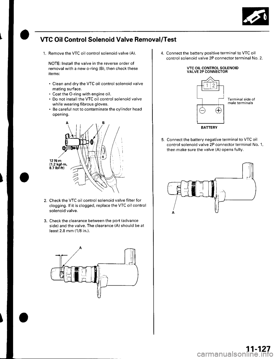
WC OilControl Solenoid Valve Removal/Test
1. Remove the WC oilcontrol solenoid valve (A).
NOTE: lnstall the valve in the reverse order of
removal with a new o-ring (B), then check these
tlems:
Clean and dry the VTC oil control solenoid valve
mating surface.
Coat the O-ring with engine oil.
Do not install the VTC oilcontrol solenoid valve
while wearing fibrous gloves,
Be careful not to contaminate the cylinder head
openrng.
Check the VTC oil control solenoid valve filter for
clogging. lf it is clogged, replace the VTC oil control
solenoid valve.
Check the clearance between the port (advance
side) and the valve. The clearance (A) should be at
least 2.8 mm (1/8 in.).
Connect the battery positive terminal to VTC oil
control solenoid valve 2P connector terminal No. 2.
VTC OIL CONTROL SOLENOIDVALVE 2P CONNECTOR
Terminal side oJmale terminals
Connect the battery negative terminal to VTC oil
control solenoid valve 2P connector terminal No. 1,
then make sure the valve (A) opens fully.
BATTERY
11-127