width HONDA CIVIC 2002 7.G Workshop Manual
[x] Cancel search | Manufacturer: HONDA, Model Year: 2002, Model line: CIVIC, Model: HONDA CIVIC 2002 7.GPages: 1139, PDF Size: 28.19 MB
Page 20 of 1139
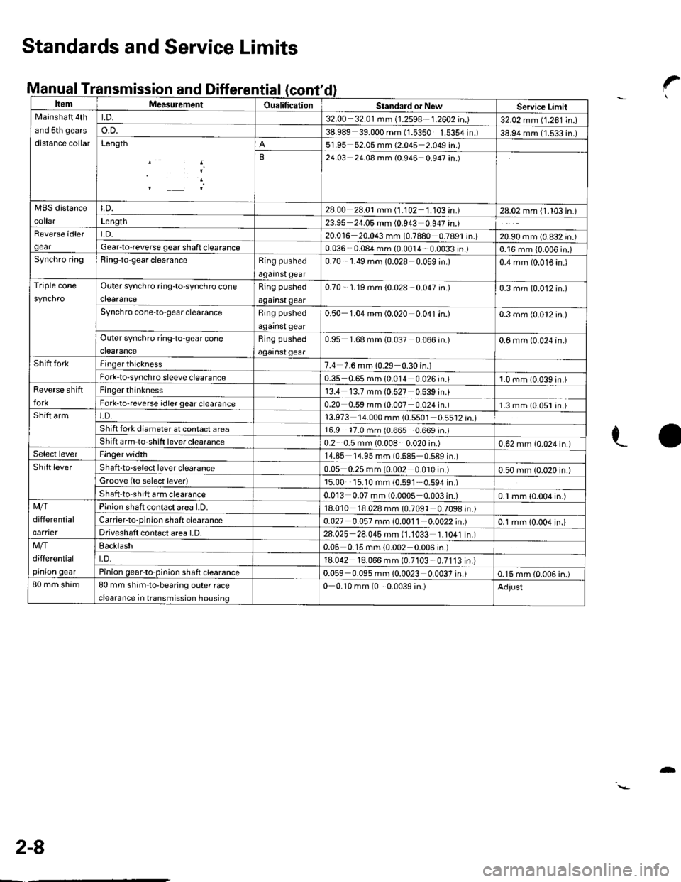
anuat I ransmcont'
ItemMeasutemenlOualificationStandard or NewServicc LimitNlainshaft 4th
and 5th gears
distance collar
LD.32.00-32.01 mm (1.2598 1.2602 in.)32.02 mm (1.261 in.)o.D.38.989 39.000 mm (1.5350 1.5354 in.)38.94 mm (1.533 in.)Length51.95 52.05 mm (2.045 2.049 in.)
B24.03 24.08 mm (0.946-0.947 in.)
MBS distanceLD.28.00 28.01mm (1.102 1.103 in.)28.02 mm (1.103 in.)Len9th23.95 24.05 mm (0.943 0.947 in.)Reverse idler
gear
t.D.20.016 20.043 mm (0.7880 0.7891 in.)20.90 mm (0.832 in.)Gear lo reverse gear shafi clearance0.036 0.08a mm (0.0014 0.0033 in.)0.16 mm {0.006 in.)Synchro ringBing to'gear clearanceRing pushed
against gear
0.70 1.49 mm (0.028 0 059 in )0.4 mm (0.016 4n.)
Triple coneOuter synchro ring-to synchro cone
clearance
Ring pushed
against qear
0.70 - '1.19 mm {0.028 0.047 in.)0.3 mm (0.012 in.)
Synchro cone-to-gear clearanceRing pushed
against gear
0.50 1.04 mm (0.020 0.041 in.)0.3 mm (0.012 in.)
Outer synchro ring-to-gear cone
clearance
Ring pushed
against gear
0.95 1.68 mm (0.037 0.066 in.)0.6 mm (0.024 in.)
Shift forkFinger thickness7.4 7.6 mm 10.29 0.30 in.)Fork to-synchro sleeve clearance0.35 0.65 mm (0.014 0.026 in.i1.0 mm (0.039 in.)Reverse shift
fork
Finger thinkness13.4 13.7 mm (0.527 0.539 in.)Fork-to-reverse idler gear clearance0.20 0.59 mm (0.007 0.024 in.)1.3 mm (0.051 in.)Shift armt.D.13.973 '14.000 mm (0.5501 0.5512 in.)Shift fork diameter at conlact area16.9 '17.0 mm (0.665 0.669 in.)Shift arm'to-shift lever clearance0.2 0.5 mm (0.008 0.020 in.)0.62 mm (0.024 in.)Select leverFinger width14.85 '14.95 mm (0.585 0.589 in.)Shift leverShaft -to-select lever clearance0.05 0.25 mm (0.002 0.010 in.)0.50 mm (0.020 in.)Groove {to select lever)15.00 15.10 mm {0.591 0.594 in.)
Shaft to shift arm clearance0.013 0.07 mm (0.0005 0.003 in.)0.1 mm {0.004 in.)Mfi
differential
carrier
Pinion shaft contact area l.D.18.010 18.028 mm (0.7091 0.7098 in.)Carrier-to-pinion shaft clearance0.027 0.057 mm (0.0011 0.0022 in.)0.1 mm (0.004 in.lDriveshaft contact area LD.28.025 28.045 mm (1.1033 1.1041 in.)Mfi
differential
pinion qear
Backlash0.05 0.15 mm {0.002 0.006 in.)
t.D.18.042 18.066 mm (0.7103 0.7113in.)Pinion gearto pinion shaft clearance0.059 0.095 mm (0.0023 0.0037 in.)0.15 mm (0.006 in.)80 mm shim80 mm shim to-bearing outer race
clearance in transmission housing
0 0.10 mm (0 0.0039 in.)Adjust
Standards and Service Limits
Manual Transmission and Differential?
LO
2-8
-
Page 23 of 1139
L
v
2-11
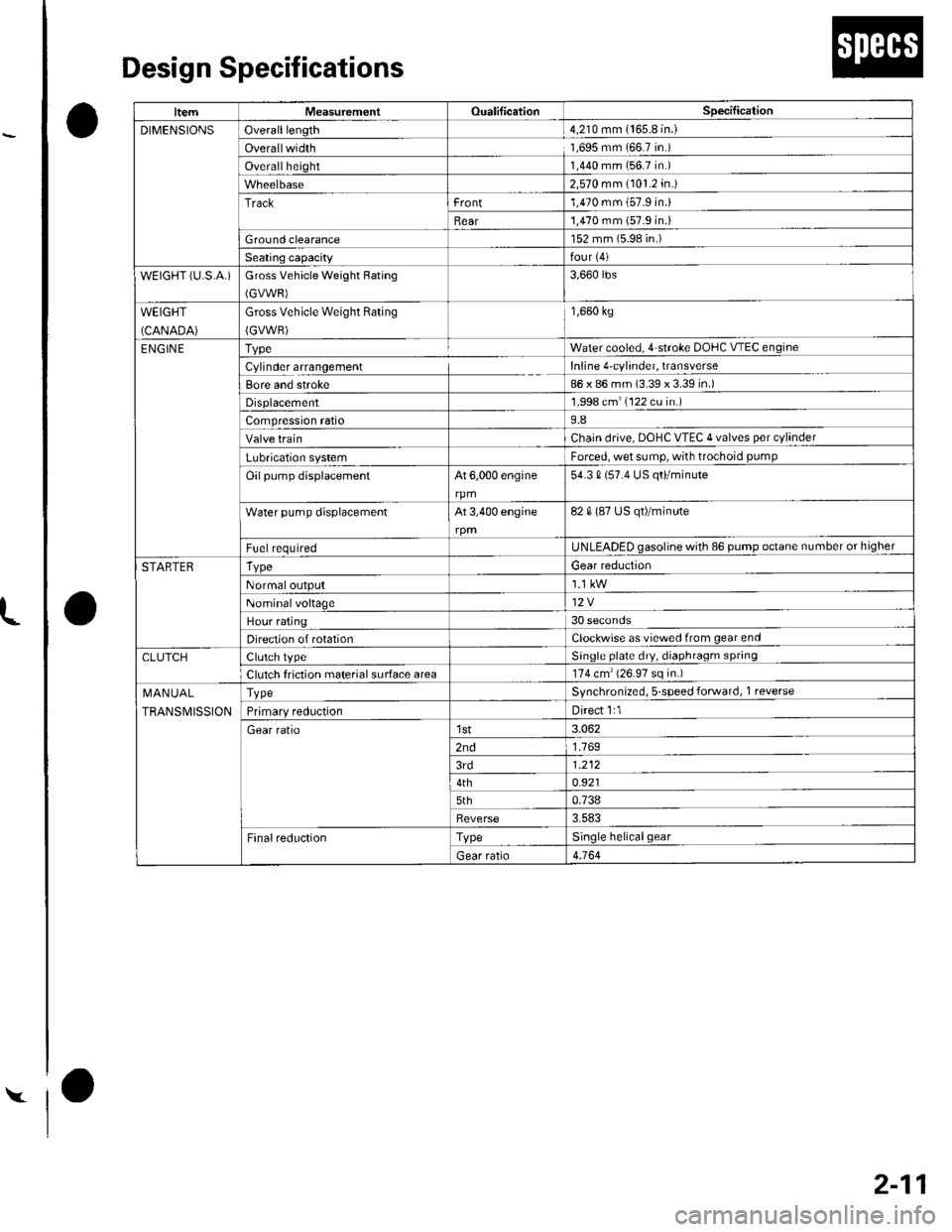
Design Specifications
O
o
o
|temMeasurementOualificationSpecilication
DIMENSIONSOveralllength4,210 mm {165.8 in.)
Overallwidth1,695 mm 166.7 in.)
Overallheight1,440 mm (56.7 in.)
2,570 mm (101.2 in.)
Trackrront1,470 mm (57.9 in.)
Rear'1,470 mm (57.9 in.i
Ground clearance152 mm (5.98 in.)
Seating capacityfour {4)
wEtGt-iT {u.s.A.)Gross Vehicle Weight Rating
(GVWR)
3,660 rbs
WEIGHT
(CANADA)
Gross Vehicle Weight Rating
{GVWR)
1,660 kg
ENGIN ETvpeWater cooled. 4 stroke DOHC V-EC engin(
Cylinder arrangementInline 4'cylinder, transverse
Bore and stroke86 x 86 mm (3.39 x 3.39 in.)
Displacement1,998 cm'(122 cu in.)
Compression ratio9.8
Valve trainChain drive. DOHC VTEC 4 valves per cylinder
Lubrication systemForced, wet sump, with trochoid pumP
Oil pump displacementAt 6,000 engine
rpm
54.3 0 (57.4 US qo/minute
Water pump displacementAt 3,400 engine82 0 (87 US qt)/minute
F!el requiredUNLEADED gasoline with 86 pump octane number or higher
STARTERTvpeGear reduction
Normaloutput
Nominalvoltage12V
Hour rating30 seconds
Direction of rotationClockwise as viewecl from gear end
CLUTCHClutch tvpeSinqle plate dry, diaphragm spring
Clutch friction material surface area174 cm'{26.97 sq in.)
I\,1AN UAL
TRANSMISSION
TvpeSvnchronized, s-speed forward, 1 reverse
Primarv reductionDirect 1:1
Gear ratiolst3.062
2nd1.769
3rd1.212
4th0.921
5th0.738
Reverse3.583
FinalreductionTypeSinole helicalgear
Gear ratio4.164
Page 130 of 1139
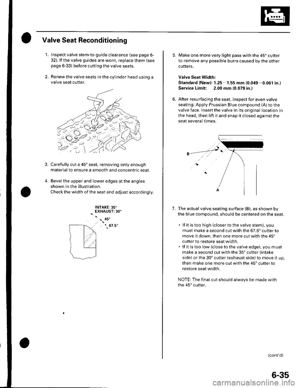
Valve Seat Reconditioning
1. Inspect valve stem-to-guide clearance (see page 6-
32). lf the valve guides are worn, replace them (see
page 6-33) before cutting the valve seats.
2. Renew the valve seats in the cylinder head using a
valve seat cutter.
Carefully cut a 45'seat, removing only enough
material to ensure a smooth and concentric seat.
Bevel the upper and lower edges at the angles
shown in the illustration.
Check the width of the seat and adjust accordingly.
INTAKE:35"EXHAUST:30'
3,
4.
- 45'
, { 67.5'
5. Make one more very light pass with the 45" cutter
to remove any possible burrs caused by the other
cutters.
Valve Seat Width:
Standard (New): 1.25 1.55 mm {0.049 0.061 in.)
Service Limit: 2.00 mm (0.079 in.)
6. After resurfacing the seat, inspect for even valve
seating: Apply Prussian Blue compound (A) to the
valve face. Insert the valve in its original location in
the head, then lift it and snap it closed against the
seat several trmes.
1.The actual valve seating surface (B), as shown by
the blue compound, should be centered on the seat.
. lf it is too high (closer to the valve stem), you
must make a second cut with the 67.5' cutter to
move it down, then one more cut with the 45"
cutter to restore seat width.. lf it is too low (close to the valve edge), you must
make a second cut with the 35'cutter (intake
sidel or the 30" cutter (exhaust side) to move it up,
then make one more cut with the 45" cutter to
restore seat width.
NOTE: The final cut should always be made with
the 45'cutter.
(cont'd)
6-35
Page 429 of 1139
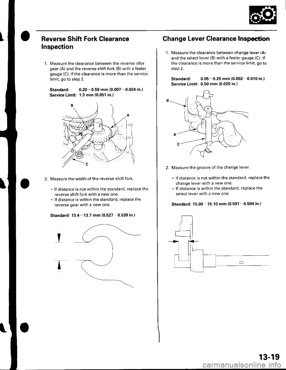
Reverse Shift Fork Clearance
Inspection
1. Measure the clearance between the reverse idler
gear {A) and the reverse shift fork (B) with a feeler
gauge (C). lf the clearance is more than the service
limit, go to step 2.
Standard: 0.20-0.59 mm (o.oo7 0.024 in.l
Service Limit: r.3 mm {0.051 in.)
Measu re the width of the reverse shift fork.
. lf distance is notwithinthestandard, replacethe
reverse shift fork with a new one.. lf distance is within the standard, replacethe
reverse gear wrln a new one.
Standard: 13.4 13.7 mm (0.527 0.539 in.l
I
Change Lever Clearance Inspection
1.Measure the clearance between change lever (Al
and the select lever (B) with a feeler gauge (Cf. lf
the clearance is more than the service limit, go ro
step 2.
Standard: 0.05 0.25 mm (0.002-0.010 in.)
Service Limit: 0.50 mm {0.020 in.)
2.Measure the groove of the change lever'
. lf distance is not within the standard, replace the
change lever with a new one.
. lf distance iswithinthe standard, replacethe
select lever with a new one.
15.00 15.10 mm (0.591-0.594 in.)Standard:
,tl
I
qI
13-19
Page 431 of 1139
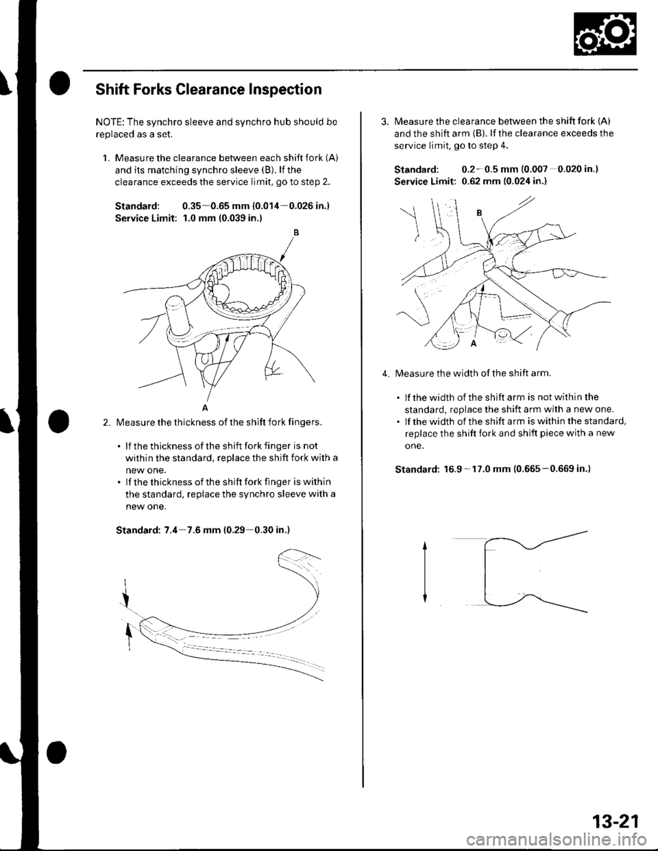
Shift Forks Glearance Inspection
NOTE: The synchro sleeve and synchro hub should be
replaced as a set.
1. Measu re the clearance between each shift fork (A)
and its matching synchro sleeve (B). lf the
clearance exceeds the service limit, go to step 2.
Standard: 0.35 0.65 mm {0.014 0.026in.1
Service Limit: 1.0 mm 10.039 in.l
A
l\4easure the thickness of the shift fork fingers.
. lf thethicknessof theshift forkfinger is not
within the standard, replace the shift fork with a
new one.. lf thethicknessof the shift forkfinger iswithin
the standard, replace the synchro sleeve with a
new one.
Standard: 7.4 7.6 mm (0.29-0.30 in.)
2.
3. Measure the clearance between the shift fork (A)
and the shift arm (B). lf the clearance exceeds the
service limit, go to slep 4.
Standard: 0.2-0.5 mm (0.007 0.020 in.)
Service Limit: 0.62 mm (0.024 in.)
Measure the width of the shift arm.
. lf thewidth of theshiftarm is notwithinthe
standard, replace the shift arm with a new one.. lf thewidth of the shift arm iswithinthe standard,
replace the shift fork and shift piece with a new
one.
Standard: 16.9-17.0 mm (0.665-0.669 in.)
4.
13-21