EPS HONDA CIVIC 2002 7.G Manual PDF
[x] Cancel search | Manufacturer: HONDA, Model Year: 2002, Model line: CIVIC, Model: HONDA CIVIC 2002 7.GPages: 1139, PDF Size: 28.19 MB
Page 557 of 1139
EPS Components
4
17.
18.
Steering Gearbox Installation (cont'dl
Install the motor on the steering gearbox (see page
17-49).
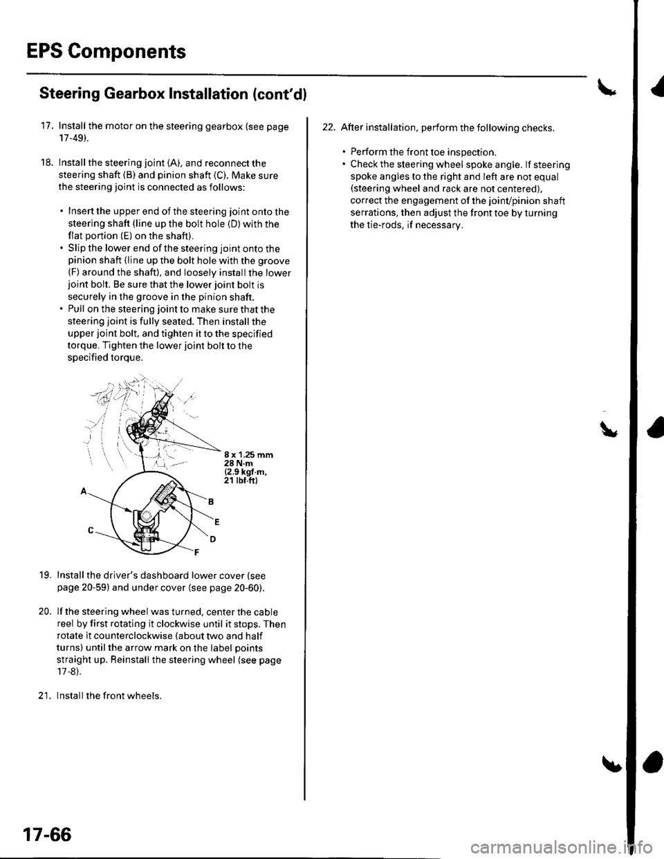
lnstall the steering joint (A). and reconnect the
steering shaft (B) and pinion shaft (C). Make sure
the steering joint is connected as follows:
. Insertthe upperend of thesteering jointontothe
steering shaft (line up the bolt hole (D) with the
flat portion (E) on the shaft).. Slip the lower end of the steering joint onto thepinion shaft (line up the bolt hole with the groove
(F) around the shaft), and loosely installthe lowerjoint bolt. Be sure that the lower joint bolt is
securely in the groove in the pinion shaft.. Pull on the steering joint to make sure that the
steering joint is fully seated. Then install the
upper joint bolt, and tighten it to the specified
torque. Tighten the lower joint bolt to the
specified torque.
8 x '1.25 mm28 N.m{2.9 kgf.m,21 tbt.ft)
19.
20.
Installthe driver's dashboard lower cover (see
page 20-59) and under cover (see page 20-60).
lf the steering wheel was turned, center the cable
reel by first rotating it clockwise until it stops. Then
rotate it counterclockwise (about two and half
turns) untilthe arrow mark on the label points
straight up. Reinstall the steering wheel (see page
17 -8).
Install the front wheels.)1
17-66
22. After installation, perform the following checks.
. Perform the front toe inspection.. Check the steering wheel spokeangle. lfsteering
spoke angles to the right and left are not equal(steering wheel and rack are not centered),
correct the engagement of the joinvpinion shaft
serrations, then adjust the front toe by turning
the tie-rods, if necessarv.
\
Page 558 of 1139
EPS Control Unit Removal/
Installation
1. Remove the passenger's under panel.
2. Turn up the floor carpel, remove lhe EPS control
untr.
Disconnect the EPS control unit connectors.
lnstallthe EPS control unit in the reverse order of
removal.
After installation, start the engine, and let it idle.
Turn the steering wheelfrom lock-to-lock several
times. Check that the EPS indicator does not come
on.
3.
E
Tie-rod Ball Joint Boot Replacement
Special Tool Required
Attachment, 42 mm 07OAD-P0A0100
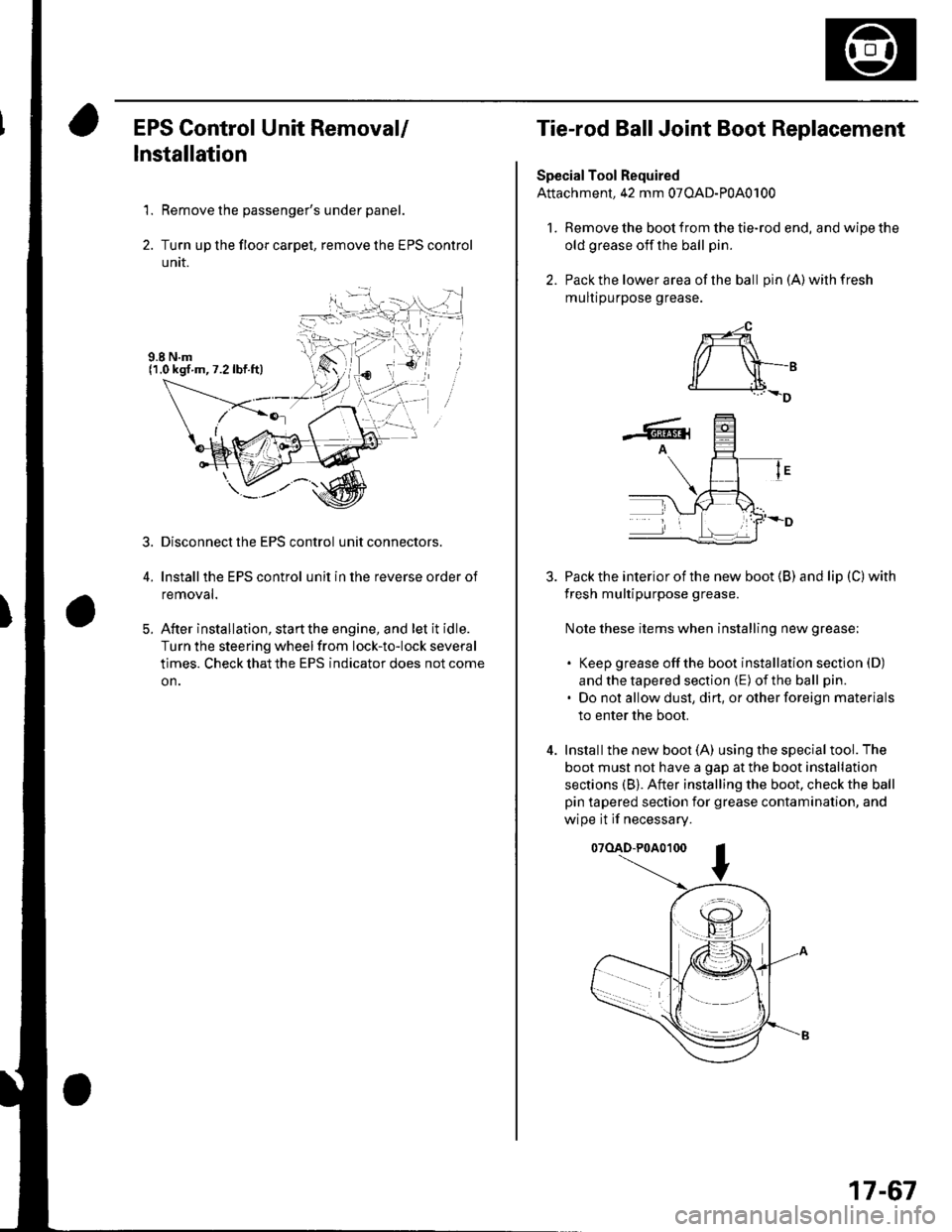
l. Remove the boot from the tie-rod end, and wipe the
old grease off the ball pin.
2. Pack the lower area of the ball pin(A)wilhfresh
mulr purpose grease.
3. Pack the interior of the new boot (B) and lip (C) with
fresh multipurpose grease.
Note these items when installing new grease;
. Keep grease offthe boot installation section (D)
and the tapered section (E) of the ball pin.
. Do not allow dust, dirt, or other foreign materials
to enter the boot.
4. Installthe new boot (A) using the specialtool. The
boot must not have a gap at the boot installation
sections (B). After installing the boot. check the ball
pin tapered section for grease contamination, and
wipe it if necessary.
07(lAD-P0A0100
*-4
r/ \-,d______i.l+_D
-6rA
17-67
Page 721 of 1139
Driver's side:
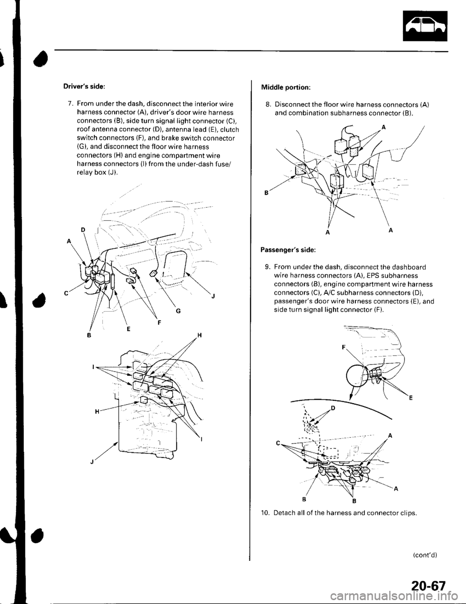
7. From under the dash, disconnect the interior wire
harness connector (A), driver's door wire harness
connectors (B), side turn signal light connector (C).
roof antenna connector (D), antenna lead (E). clutch
switch connectors (F), and brake switch connector(G), and disconnect the floor wire harness
connectors (H) and engine compartment wire
harness connectors (l)from the under-dash fuse/
relav box (J).
Middle portion:
8. Disconnect the floor wire harness connectors (A)
and combination subharness connector (B).
Passenger's side:
9. From under the dash, disconnect the dashboard
wire harness connectors (A), EPS subharness
connectors (B), engine compartment wire harness
connectors (C), A,/C subharness connectors (D),
passenger's door wire harness connectors {E), and
side turn signal light connector (F).
10. Detach all of the harness and connector clips.
(cont'd)
20-67
Page 811 of 1139
Heating and Air Gonditioning
Blower Unit Removal and Installation {cont'd}
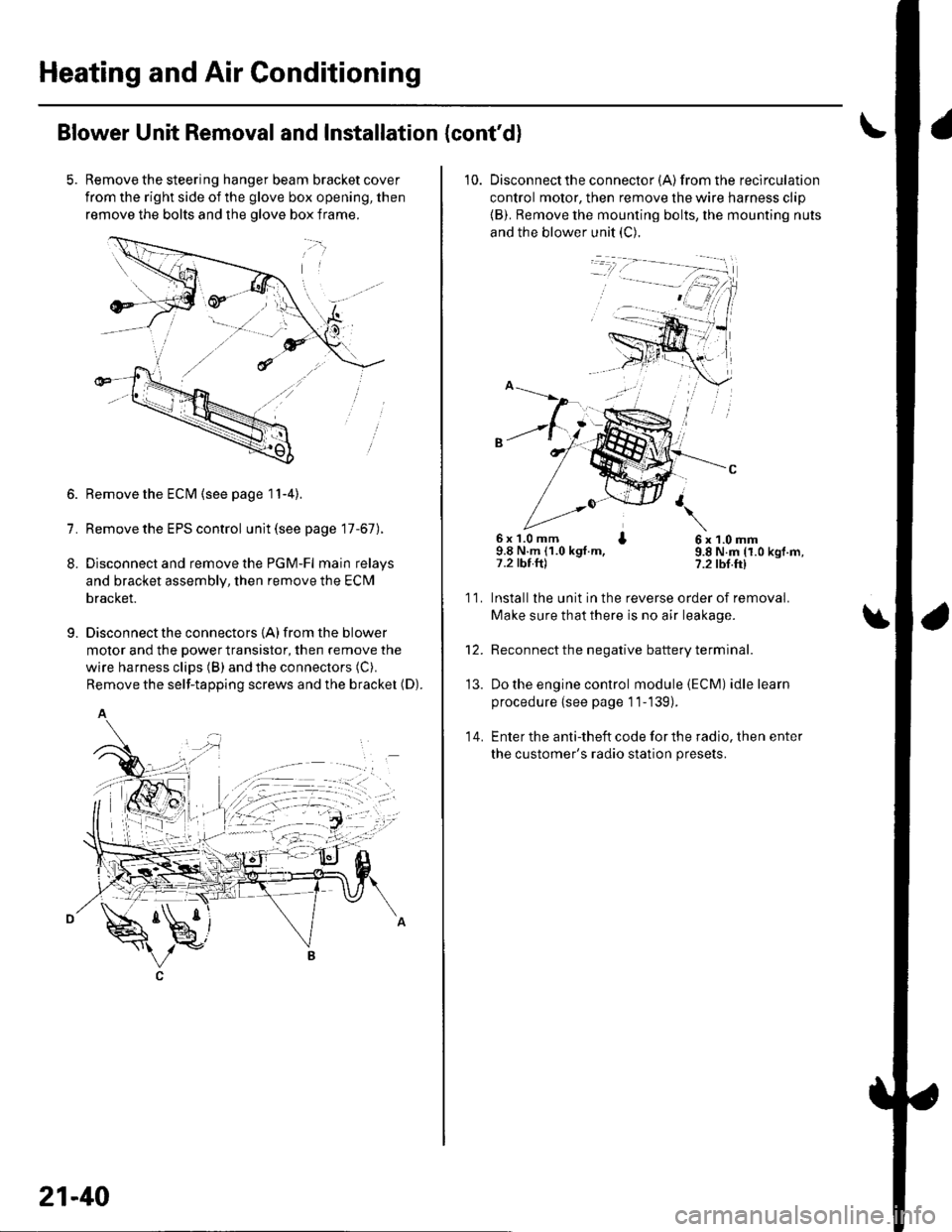
Remove the steering hanger beam bracket cover
from the right side of the glove box opening, then
remove the bolts and the olove box frame.
1.
8.
9.
Remove the ECM (see page 11-4).
Remove the EPS control unit (see page 17-67).
Disconnect and remove the PGM-Fl main relays
and bracket assembly, then remove the ECM
bracket.
Disconnect the connectors {A) from the blower
motor and the power transistor, then remove the
wire harness clips (B) and the connectors (C).
Remove the self-tapping screws and the bracket (D).
A
21-40
10. Disconnectthe connector {A) from the recirculation
control motor, then remove the wire harness clip
{B). Remove the mounting bolts, the mounting nuts
and the blower unit (C).
6x 1.0 mm I9.8 N.m (1.0 kgt.m,7.2 tbt.ftl
6x1.0mm9.8 N.m (1.0 kgf.m,?.2 tbf.ft)
11.
14.
Installlhe unit in the reverse order of removal.
Make sure that there is no air leakage.
Reconnect the negative battery terminal.
Do the engine control module (ECM) idle learn
procedure {see page 11-139).
Enter the anti-theft code for the radio, then enter
the customer's radio station presets.
\
'13.
Page 841 of 1139
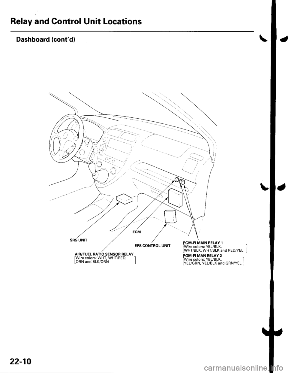
Relay and Control Unit Locations
a
\
Dashboard (cont'd)
L
SRS UNIT
EPS CONTROL UNITPGM.FI MAIN RELAY 1lWire colors: YEUBLK,LWHT/BLK, WHT/BLK and RED/YEL
PGM.FI MAN RELAY 2fwire colors: YEUBLK, ILYEUGRN, YEUBLK and GRN/YEL I
AIR/FUEL RATIO SENSOR RELAY[Wire colorsr WHT, WHT/RED, IOBN and BLK/ORN I
22-10
Page 844 of 1139
Gonnectors and Harnesses
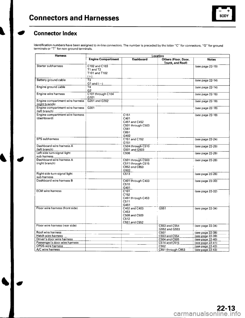
aGonnector Index
ldentification numbers have been assigned to in-line connectors. The number is preceded by the letter "C" for connectors, "G" for groundterminals or "T" for non ground terminals.
HamessLocationEngine CompartmentDashboardOthers {Floor, Door,Trunk. and Roo{lNot€s
Starter subharnessC102 and C103T1 and T2T101 and T102
(see page 22-15)
Battery ground cableT3G'l and ( -{see page 22-l!)
Engine ground cableT4{see page 22-14)
Engine wire harnessCl0l through C104G 101(see page 22 16)
Engine compartment wire harness{rioht branchiG201 and G202(see page 22 18)
Engine compartment wire harness(left brench)G301(see page 22 18)
Engine compartment wire harness(dashboard)c401C451 and C452C501 through C503c551c851G402
(see page 22-18)
EPS subharnessC151 and C152G'151\see page 22 241
Dashboard wire harness Alleft branch)C504 through C510G501 and G503(see page 22-26)
Left side turn signal lightc506(see page 22-26)
Dashboard wire harness A(right branch)C50l through C503C5ll through C515C852 and C853G502
(see page 22-26)
Right side turn si9nal lightsub harnesslsee page 22-26)
Dashboard wire harness BC40l through C403c510G40l
(see page 22-30)
ECM wire harnessc101cl52C451 through C453c511G451
{see page 22-32}
Floorwire harness (front side)C402 and C403 G551c453C508 and C509c512C551 an.l C55?
(see page 22'34)
Floor wire harness (rear side)C553 and C554(see page 22-34)
Roo{ wire harnessc507(see paqe 22-38)Hatch wire harnessC553 and C554(s6e paqe 22'39)Driver's door wire harnessC504 and C505(see paqe 22-40)Passenqer's door wi.e harness514 and C515(see oaoe 22-41Te harness)552(see oaqe 22-42i/C wire harnessc851 rhrouoh c853(see paqe 22.43i
22-13
Page 853 of 1139
Connectors and Harnesses
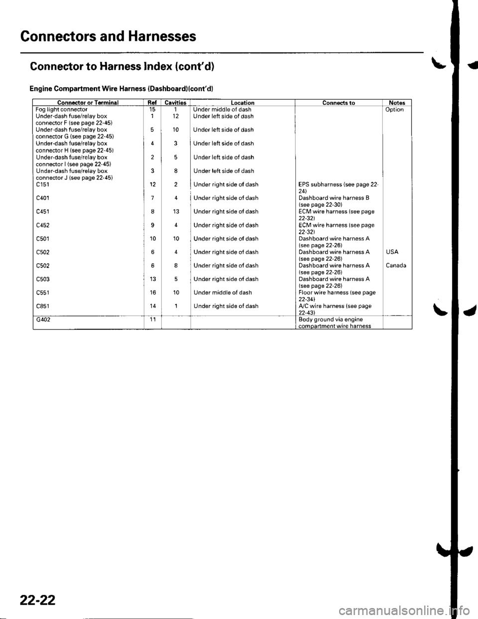
Connector to Harness Index (cont'd)
Engine Compartment Wire Harness (Dashboard)lcont'dl
Connector or TerminalCavitiesLocationConnectstoNotesFog light connectorUnder'dash fuse/relay boxconnector F (see page 22-45)Underdash fuse/relay boxconnector G (see page 22-45)Underdash fuse/relay boxconnector H (see page 22'45)Under-dash fuse/relay boxconnector | (see page 22'45)Under-dash fuse/relay boxconnector J (see page 22-45)c 151
c401
c451
c452
c501
c502
c502
c503
c851'14
2
3
1
I
9
6
6
5
5
12
10
112
10
3
5
8
2
'10
4
8
5
10
1
Under maddle of dashUnder left side of dash
Under left side of dash
Under left side of dash
Under left side of dash
Under left side ol dash
Under right side of dash
Under right side ot dash
Under right side ot dash
Under right side oJ dash
Under right side oI dash
Under right side ol dash
Under right side oJ dash
Under right side oJ dash
Under middle of dash
Under right side of dash
EPS subharness {see page 22-24)Dashboard wire harness B(see page 22-30)ECM wire harness (see page22-321ECM wire harness (seo page22 32)Dashboard wire harness A(see page 22-26)Dashboard wire harness Alsee page 22-261Dashboard wire harness A(see page 22-26)Dashboard wire harness A(see page 22-26)Floorwire harness (see page22-34l',VC wire harness lsee page22-43\
Oplion
Canada
USA
G4021'�IEody ground via engine..mdarlma.t w,rc harncss
22-22
Page 855 of 1139
Connectors and Harnesses
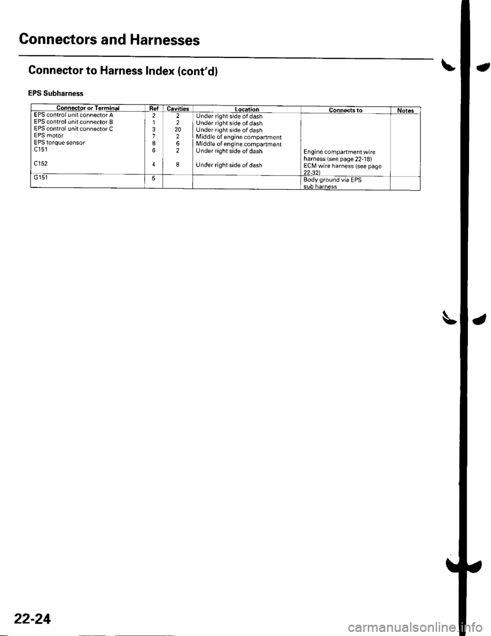
Connector to Harness lndex (cont'dl
EPS Subharness
Connector or TerminalCavitiesLocationConnects toNotesEPS control unit connectorAEPS control unit connector BEPS control unit connector CEPS motorEPS torque sensorc 151
c152
2,l
31
6
4
2220262
I
Under rightside ofdashUnder right side of dashUnder righr side of dashMiddle of engine companmentMiddle of engine compartmentUnder right side of dash
Under right side of dash
Engine compartment wireharness (see page 22- 18)ECI\,4 wire harness (see page22-321G 1515aody ground via EPS
22-24
Page 856 of 1139
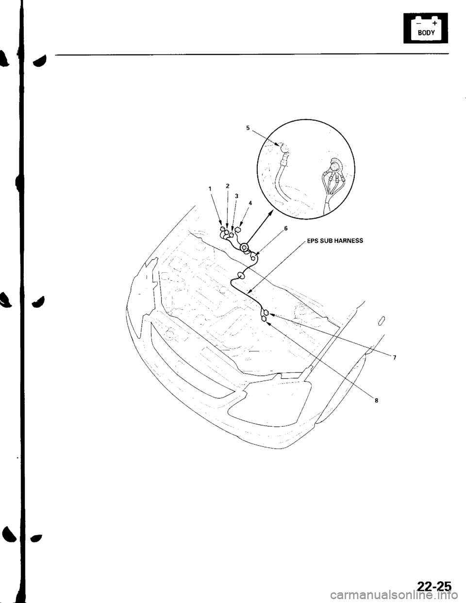
EPS SUB HARNESS
22-25
Page 863 of 1139
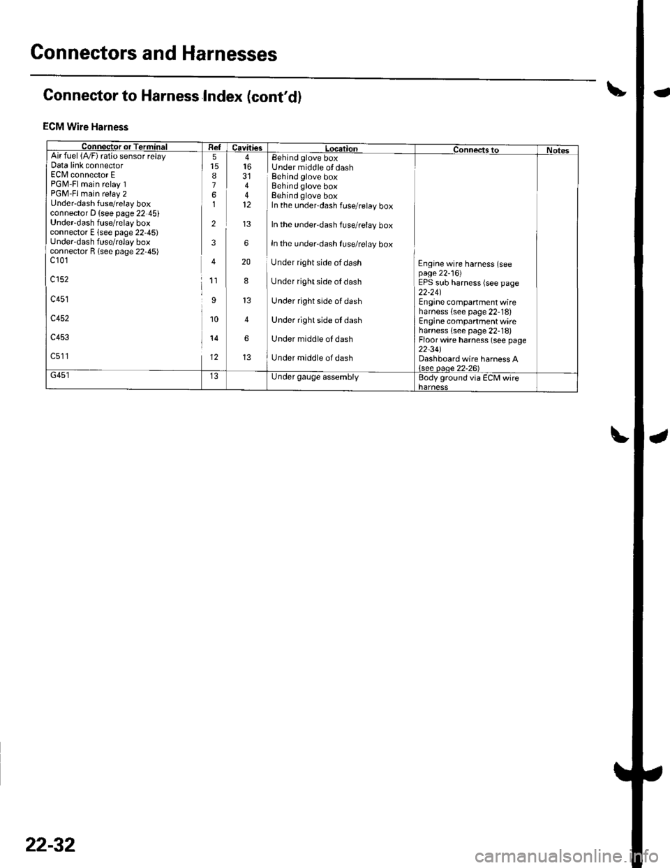
Connectors and Harnesses
Connector to Harness Index (cont'd)
ECM Wire Harness
Connector or TerminiFI Re-lcavitiesL LocationConnectstoNotesArr ruer t/vrl ralo sensor retayData link connectorEC[/l connector EPGM-Fl main relay 1PGM-Fl main relay 2Under-dash fuse/relay boxconnector D (see page 22 45)Underdash fuse/relay boxconnector E lsee page 22-45)under-dash fuse/relay boxconnector R lsee page 22-45)c10'1
c152
c451
c452
c453
c511
8761
2
3
4
1'�I
I
10
14
12
44
6
20
8
4
6
Eehind glove boxUnder middle of dashBehind glove boxBehind glove boxBehind glove boxIn the under-dash fuse/relay box
In the under-dash fuse/relay box
In the under-dash fuse/relay box
Under rlght side of dash
Under right side of dash
Under right side of dash
Under right side ot dash
Under middle oI dash
Under middle of dash
Engine wire harness (seepage 22'16)EPS sub harness (see page22-24)Engine companment wireharness {see page 22-18)Engine compartment wireharness {see page 22-18)Floor wire harness (see page22-34)Dashboard wire harness A{see oaoe 22-26)G451Under gauge assemblyBody ground via ECM wireharness
22-32