EPS HONDA CIVIC 2002 7.G Manual Online
[x] Cancel search | Manufacturer: HONDA, Model Year: 2002, Model line: CIVIC, Model: HONDA CIVIC 2002 7.GPages: 1139, PDF Size: 28.19 MB
Page 877 of 1139
Power Distribution
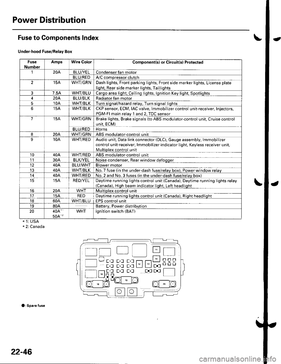
Fuse to Components lndex
Under-hood Fuse/Relay Box
Fuse
Number
AmpsWire ColorComponent(sl or Circuit(s) Protected
'I204BLUI/ELCondenser fan motor
BLU/REDAy'C compressor clutch
15AWHT/GRNDash lights, Front parking lights, Front side marker lights, License plate
liqht, Rear side marker liqhts, Tailliqhts
7.5AWHT/BLUCarqo area liqht, Ceilinq liqhts. lqnition Kev liqht. Sootliohts
204BLU/BLKRadiator fan motor
510AWHT/BLKTurn siqnal/hazard relav, Turn siqnal liqhts
15AWHT/BLKCKP sensor, ECM, IAC valve, lmmobilizer control unit-receiver, Injectors,
PGM-FI main relav 1 and 2. TDC sensor
715AWHT/GRNBrake lights, Brake signals (to ABS modulator-control unit, Cruise control
unit, ECM)
BLU/REDi1 Orns
820AWHT/GRNABS modulatorcontrol unit
910AWHT/REDAudio unit, Data link connector (DLC), Gauge assembly, lmmobilizer
control unit-receiver, lmmobilizer indicator light. Keyless receiver unil,
lvlultiDlex control unit
1040AWHT/REDABS modulator-control unit
1130AB LK/YE LNoise condenser, Rear window defoqqer
40ABLU^^/HTBlower motor
IJ40AWHT/BLKNo. 7 fuse (in the under-dash fuse/relav box), Power window relav
1440AWHT/REDNo.2 and No.3 fuses (in the under-dash fuse/relav box)
t515AREDI/ELDaytime running lights control unit (Canada), Daytime running lights relay
{Canada), Hioh beam indicator liqht. Left headliqht
16204WHTMultiplex control unit
1715AREDDavtime runninq liqhts control unit (Canada). Rioht headlioht
1860AWHTiBLUEPS control unit
1980ABatterv. Power distribution
2040A'
50A'?
WHTlgnition switch (BAT)
* 1: USA" 2. Canada
O: Spare fuse
t t"| lll Itt 4t I
l l---- E'l E,l E,l r--r r---r t__J i; i6'!/'
E,l E,l E,l Eol E l f__--lI l'lr]n | |I r L__J,a ,..r^{-------l^-,
n[:]$"Lrt " N2, nf - r^l
22-46
Page 878 of 1139
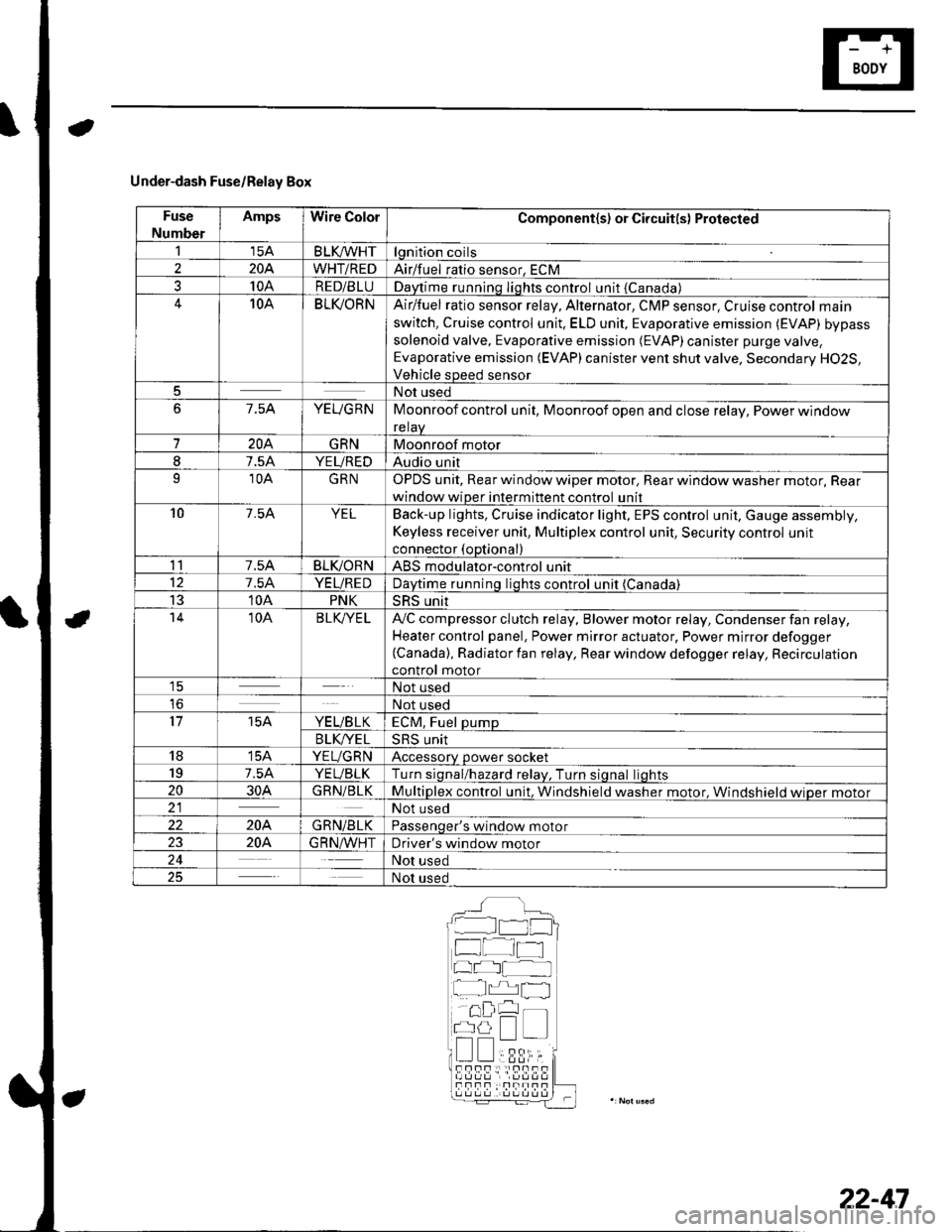
Under-dash Fuse/Relay Box
Fuse
Number
AmpsWire ColorComponent(s) or Circuit(s) Protected
115ABLKA/VHTlgnition coils
2204WHT/REDAirlfuel ratio sensor, ECM
310ARED/BLUDaytime running Iights control unit {Canada)10ABLI(ORNAir/fuel ratio sensor relay, Alternator, CMP sensor, Cruise control main
switch, Cruise control unit. ELD unit, Evaporative emission (EVAP) bypass
solenoid valve, Evaporative emission (EVAP)canister purge valve,
Evaporative emission (EVAP) canister vent shut valve, Secondary H02S,
Vehicle speed sensor
5Not used
67.5AYEUGRNMoonroof control unit, Moonroof open and close relay, Power window
relaV
7204GRNMoonroof motor
I7.5AYEUREDAudio unit
910AGRNOPDS unit, Rear window wiper motor, Rear window washer motor, Rear
window wiper intermittent control unit
107.54YELBack-up lights, Cruise indicator light, EPS control unit, Gauge assembly,
Keyless receiver unit, Multiplex control unit, Security control unit
connector (optional)
117.5ABLIVORNABS modulator-control unit
127.5AYEUREDDaytime runnino liohts control unit (Canada)
1310APNKSRS unit't410ABLK/YE LA,,/C compressor clutch relay, Blower motor relay, Condenser fan relay,
Heater control panel, Power mirror actuator, Power mirror defogger(Canada), Radiator fan relay, Rear window defogger relay, Recirculation
control motor1ENot used
loNot used
1715AYE L/B LKECM, Fuel pump
B LK/YE L>H> Unrr
1815AYEUGRNAccessory power socket
197.5AYEUBLKTurn siqnal/hazard relav, Turn siqnal liohts
2030AGRN/BLKMultiplex control unit, Windshield washer motor. Windshield wioer motor21Not used
22204GRN/BLKPassenqer's window motor
2320A.G R N,A/VHTDriver's window motor
24Not used
25Not used
__^:Hr tl_l
f at-t
at I
r^,rl fl
!!;r -
!339,i;s!!sf Fnf : |rnITf
22-47
Page 879 of 1139
Ground Distribution
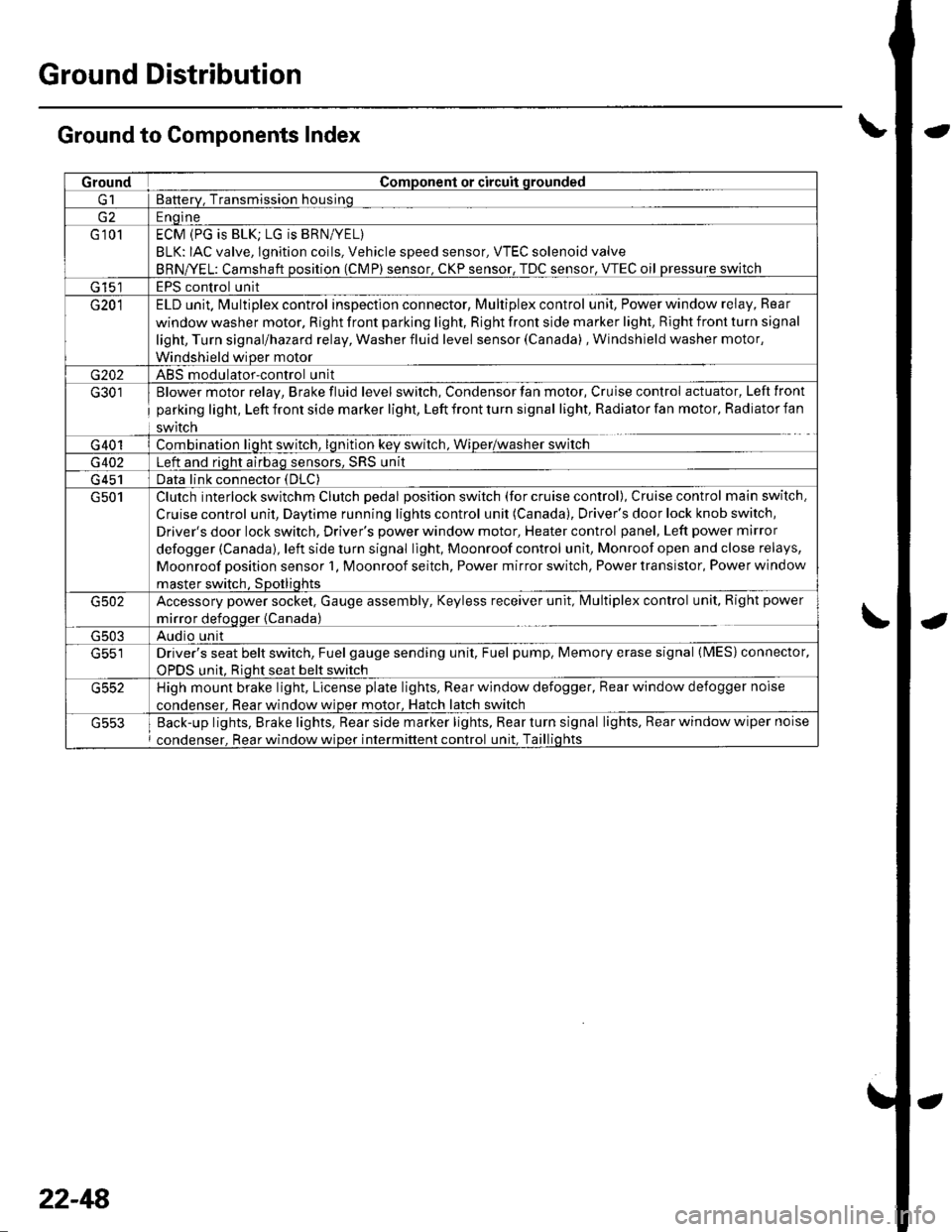
Ground to Components Index
GroundComponent or circuit qrounded
Batterv, Transmission housinq
E ngine
G 101ECM (PG is BLK; LG is BRN/YEL)
BLK: IAC valve, lgnition coils, Vehicle speed sensor, VTEC solenoid valve
BRNA/EL: Camshaft oosition (CMP) sensor. CKP sensor, TDC sensor. VTEC oil pressure switch
G 15'�]EPS control unit
G201ELD unit. Multiplex control inspection connector, Multiplex control unit, Power window relay, Rear
window washer motor, Right front parking light, Right front side marker light, Right front turn signal
light, Turn signal/hazard relay, Washer fluid level sensor (Canada) , Windshield washer motor,
Windshield wiDer motor
G202ABS modulator-control unit
G301
G401
Blower motor relay, Brake fluid level switch, Condensor fan motor, Cruise control actuator, Left front
parking light, Left front side marker light, Left front turn signal light, Radiator fan motor, Radiator fan
swrtcn
Combination liqht switch, lqnitlon kev srvitch, Wiper/wasfrer sr,virch
G402Left and riqht airbaq sensors, SRS unit
G 451Data link connector (DLC)
G501Clutch interlock switchm Clutch pedal position switch (for cruise control), Cruise control main switch,
Cruise control unit, Daytime running lights control unit (Canada), Driver's door lock knob switch,
Driver's door lock switch, Driver's power window motor, Heater control panel, Left power mirror
defogger (Canada), left side turn signal light, Moonroof control unit, Monroof open and close relays,
Moonroof position sensor '1, Moonroof seitch, Power mirror switch, Power transistor, Power window
master switch. SDotliqhts
G502Accessory power socket, Gauge assembly, Keyless receiver unit, lvlultiplex control unit, Right power
mirror defogger {Canada)
G503Audio unit
G551Driver's seat belt switch, Fuel gauge sending unit, Fuel pump, Memory erase signal (IMES) connector,
OPDS unit. Rioht seat belt switch
G552High mount brake light, License plate lights, Rear window defogger, Rear window defogger noise
condenser. Rear window wioer motor, Hatch latch switch
Back-up lights, Brake lights, Rear side marker lights, Rear turn signal lights, Rear window wiper noise
condenser, Rear window wiper intermittent control unit, Taillights
22-48
Page 992 of 1139
Transmitter Test
NOTE:. lf the doors unlockorlockwiththetransmitter, but
the LED on the transmitter does not come on, the LED
is faulty. Replace the transmitter,. lf anydoor isopen, you cannotlockthedoorwiththe
transmrtter.. lf you unlocked the doors with the transmitter, but do
not open any of the doors within 30 seconds, the
doors relock automatically.. The doors do not lock or unlock with the transmitter if
the ignition key is inserted in the ignition switch.
1. Press the lock or unlock button five or six times to
reset the transmitter.
. lf the locks work, the transmitter is OK.. lf the locks don't work, go to step 2.
2. Open the transmitter and check for water damage.
. lf you find any water damage, replace the
transmrtter.. lf there is no waterdamage, go to step 3.
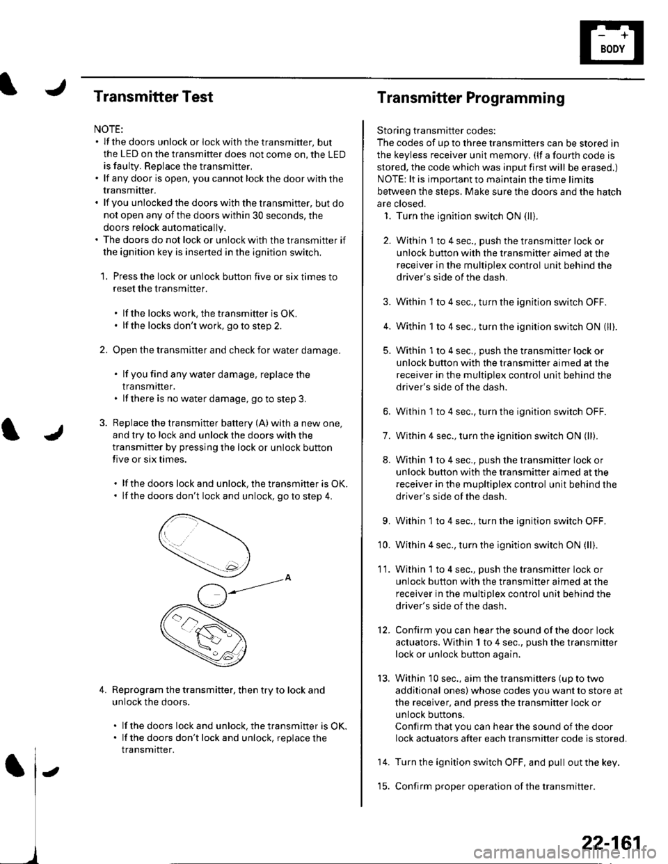
3. Replace the transmitter battery (A) with a new one,
and try to lock and unlock the doors with the
transmitter by pressing the lock or unlock button
five or six times.
. lf the doors lock and unlock, the transmifter is OK.. lf the doors don't lock and unlock, go to step 4.
Reprogram the transmitter, then try to lock and
unlock the doors.
. lf thedoors lockand unlock.thetransmitter is OK.. lf the doors don'tlockand unlock, replacethe
transmitter.
4.
Transmitter Programming
Storing transmitter codes:
The codes of up to three transmitters can be stored in
the keyless receiver unit memory. (lf a fourth code is
stored. the code which was input first will be erased.)
NOTE: lt is important to maintain the time limits
between the steps. Make sure the doors and the hatch
are closed.
1. Turn the ignition switch ON (lli.
2. Within 1 to 4 sec., push the transmitter lock or
unlock button with the transmitter aimed at the
receiver in the multiplex control unit behind the
driver's side of the dash.
3. Within 1 to 4 sec., turn the ignition switch OFF.
4. Within 1 to 4 sec., turn the ignition switch ON (ll).
5. Within 'l to 4 sec., push the transmitter lock or
unlock button with the transmitter aimed at the
receiver in the multiplex control unit behind the
driver's side of the dash.
6. Within 1 to 4 sec., turn the ignition switch OFF.
7. Within 4 sec., turn the ignition switch ON (ll).
8. Within 1 to 4 sec., push the transmitter lock or
unlock button with the transmifter aimed at the
receiver in the mupltiplex control unit behind the
driver's side of the dash.
9. Within 1 to 4 sec., turn the ignition switch OFF,
'10. Within 4 sec., turn the ignition switch ON (ll).
11. Within 1 to 4 sec., push the transmitter lock or
unlock button with the transmitter aimed at the
receiver in the multiplex control unit behind the
driver's side of the dash.
12. Confirm you can hearthe sound ofthe door lock
actuators. Within 1 to 4 sec., push the transmitter
lock or unlock button again,
13, Within 10 sec., aim the transmitters (up to two
additional ones) whose codes you want to store at
the receiver, and press the transmitter lock or
unlock buttons.
Confirm that you can hear the sound of the door
lock actuators after each transmitter code is stored.
14. Turn the ignition switch OFF, and pull out the key.
'15. Confirm proper operation ofthe transmitter.
22-161
Page 1125 of 1139
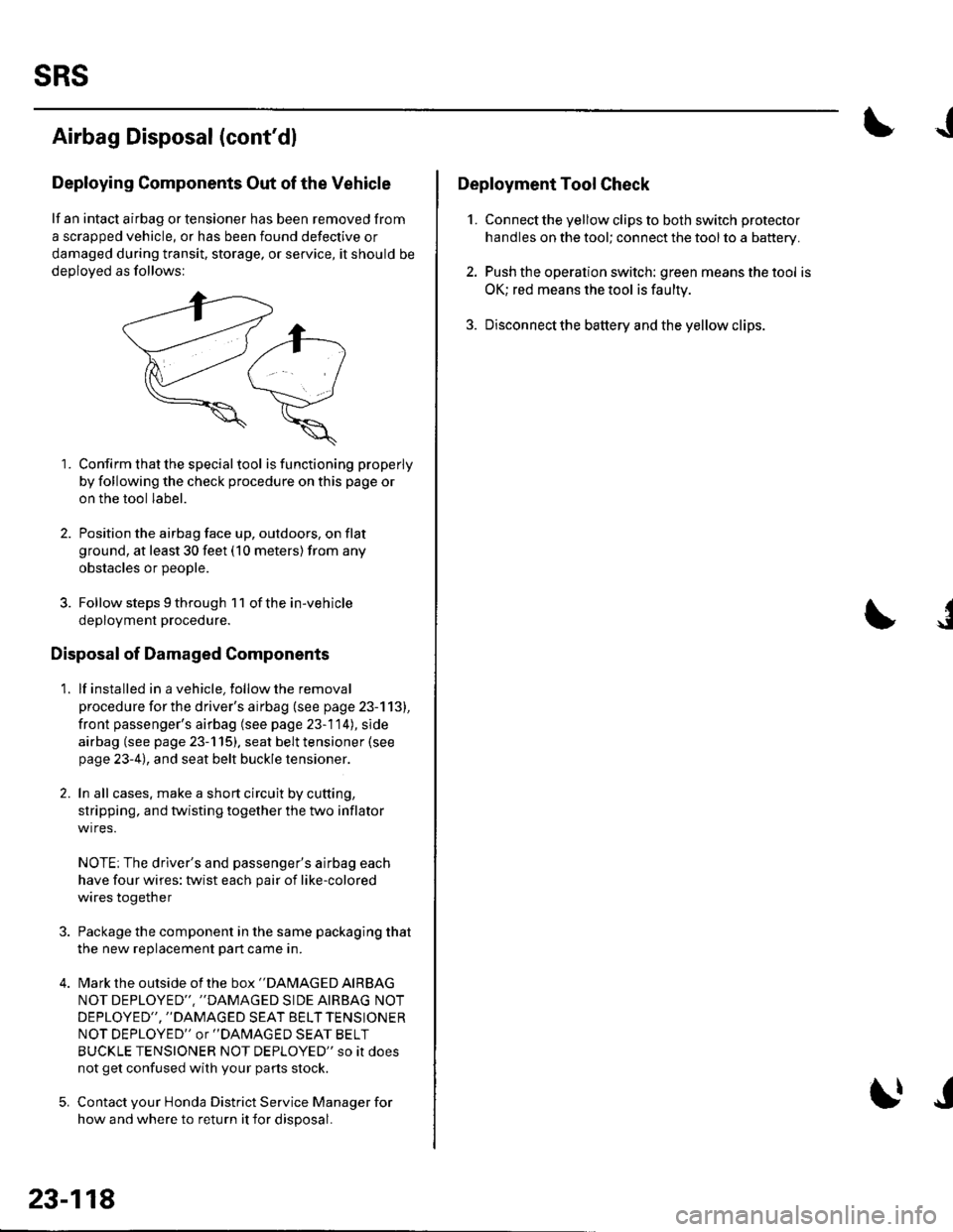
sRs
Airbag Disposal (cont'dl
Deploying Components Out of the Vehicle
lf an intact airbag or tensioner has been removed from
a scrapped vehicle, or has been found defective or
damaged during transit, storage, or service, it should be
deoloved as follows:
1. Confirm that the special tool isfunctioning properly
by following the check procedure on this page or
on the tool label.
2. Position the airbag face up, outdoors, on flat
ground, at least 30 feet (10 meters) from any
obstacles or DeoDle.
3. Follow steps 9 through 1 1 of the in-vehicle
deployment procedure.
Disposal of Damaged Components
1. lf installed in a vehicle, follow the removal
procedure for the driver's airbag (see page 23-113),
front passenger's airbag (see page 23-114), side
airbag (see page 23-115). seat belt tensioner (see
page 23-4), and seat belt buckle tensioner.
2. In all cases. make a short circuit by cutting,
stripping, and twisting together the two inflator
wires.
NOTE; The driver's and passenger's airbag each
have four wires: twist each pair of like-colored
wires together
Package the component in the same packaging that
the new reolacement Dart came in.
Mark the outside of the box "DAMAGED AIRBAG
NOT DEPLOYED'" ''DAMAGED SIDE AIRBAG NOT
DEPLOYED", "DAMAGED SEAT BELT TENSIONER
NOT DEPLOYED" or "DAlvlAGED SEAT BELT
BUCKLE TENSIONER NOT DEPLOYED" so it does
not get confused with your parts stock.
Contact your Honda District Service Manager for
how and where to return it for disposal.
23-118
I|J
J
Deployment Tool Check
1. Connect the yellow clips to both switch protector
handles on the tool; connect the tool to a battery.
2. Push the operation switch: green means the tool is
OK; red means the tool is faulty
3. Disconnectthe battery and the yellow clips.
J
Page 1133 of 1139
Service Manual lndex
)s
NOTE: Referto the lollowing listto look up A/C Pressure Switch CircuitDTCS, symptoms, fuses, connectors, wire Troubleshooting ......... ...-.-....-...-.-.-....-..21-32 Bharnesses, specifications, maintenanceschedules, and general serviceinlormation:
DTC Troubleshooting Indexes
A/C Signal CircuitTroubleshooting.........................-...... 11-'133 Back-up Light SwitchTest .......................................................... 13'3A/F lAir Fuel Ratiol SensorABS/TCS Components ........................ 19-34 Replacement ....................................... 1 1-113 Back-up Li9ht3EPS Components ................................. '17-22 Circuit DiagramFueland Emissions11-i A-Dillar Corner Trim
ABS Indicator Circuit
Heating/Ventilation ................................ 21-9 Replacement ...............-.....-..............-.... 20,96 Ball Joint BootssRS ........................................................ 23-28Replacement ......
... 19-52 Ball Joints
22-75
18 16
Remova1.............-.......... . ...........18-10Symptom Troubleshooting Indexes TroubleshootingABS/TCSComponents........................ 19 35Cruise Control System ..........................4 38 ABS Modulator-contml UnitEPS Components ................................. 17-23 Bemoval/lnstallation ............................ 19-57 BettervFan Controls10,12
Accessory Powor Socket Front
Blowor Pow€r Transistor
.......22 50
Blower UnitRemoval/lnstallation ............................ 21-39
Fuel and Em issions .............................. 11-10 ABS/TCS ComoonentsHeating/Ventilation..............................21 10 Component Location Index ................. 19-30 Beverage Holder
SRS ........................................................ 23'30 CircuitDiaqram.......................... 19'42Blower MotorReplacement .....21 41
21-38
Power 0istribution ...............................22-46 TesVReplacement .............................. 22'149Under-dash Fuse/Relay Box ............... 22 45Under-hood Fuse/Belay Box ...............22 44 Accessory Power Sockets
Fuse/Relay lndexes
(to harness)
Connector and Wire Harness lndexesComponent Connectors
Circuit Oiagram .................................. 22-149
Air Cleaner......2214 Rep1acemen1.....................................11-162
Air MixControl MotorMeintenence section .................... Section 3 Replacement ......................................... 21'34 Brake CelipersTest......................21-34 Overhaul19-14,23Gene.al lnlormation section........ Section 1
21.57
Airbag. Driver's
Ahernator FR Signal CircuitTroubleshooting .... .........-..........11 134
AntennaReplacement
Inspection ............................................. 19-24Rep|acement................. .................... 19-25
Bieke Meder Cylinder
Irake Discs
A
Replacement ....................................... 23 1 'l3 Inspection .................... ................... 19-13,22Repair ...........-...................................... 23 1 16Brake Fluid Level SwitchAirbag. Front Passenger's TestBeplacement....................................... 23-1 14AIC Brake LightsComponent Location fndex ...................21-3 Altemator CircuitDiagram....................................22-74Description.....................................-....21'1'l Beplacement ................ ........................... 4 29CircuitDiagram....................................21-14 Overhaul .................................................4-30 Brake Lines and Hoses
19.10
A/C CompressolReplacement .......-...-............................. 21 -41
A/C Compr€ssor ClulchRep1acement......................................... 19-15.........22-103 Inspection ............................................. 19-16Inspecton........Overhaul ..........
A/C CondenserReplacement,.,
21-442l-49 Audio Unit
Replacement
Brake PadsRemoval/lnstallation .. ........................22-100 Inspection/Rep1acement................ 19-11,20A/C Compressor Clutch CircuitTroubleshooting ................................... 21-30 Audio Unit Connector Brake Pedal22101 Adjustment..............19,6ArfC Comoressor Relief ValvcReplacement ..........-...-.......................... 21-51 Audio/Entertainment
A/C Compr$sor Thermal Protector Circuit DiagramReplacement............-............................ 21-51
Component Location In dex .................22-9A Test .......-.............. 22-84Breke Pedal Posilion Switch
Brake Pedal Position Switch Signal Clrcuit11-137
.....21 52
A/C Condenser Fan CircuitTroubleshooting ................... . . . . . .....21-28
)s
Troubleshooting
(cont'd)
Page 1135 of 1139
)
Orive BehInspecaron................ 4-26
Door PanelsRemoval/lnstallation -............................. 20-4
Door Sash TrimRep1acement......................................... 20 10
Door StrikersAdiustment ........................................... 20-13
Door Weatherst psBeplacement...........-............................. 20 1 1
EPS Conirol UnitRemoval/1nsta11ation ..................-......... 17-67
EPS Indicator CircuitTroubleshooting ................................... 17 -47
EPS MotorRemoval/lnstallation .-.......................... 17-49
EVAP CanisterRep1acement......................... ......... 11,189
EVAP Control Syst€mComponentLocation Index ..............'11-170
EVAP Two-Wey ValveTest ..........-.............-............................ 11 186
Evaporetor CoreRep1acement........................ . ... 21-42
Evaporator Tomperature SensorReplacement......................................... 21 -37Test..................................... ..........2137
EvaporrtoFHeater UnitReplacement........................................ 21 43
Exhaust ManifoldRemoval/1nsta11ation ................................ I 7
Exhaust Pipe8ep|acement............................................. 9-8
Front SpeakersRep|acement....................................... 22-102
Front SuspensionComponentLocation Index................... 18-3
Fueland EmissionsDescription ........................................... 11-12
Fuel Fill DoorAdjustment ..........-................................ 20 93
Fuel Fill Door OpenetBeplacement........................ . ............ 20.109
Fuel Fill Door Opener CableReplacement....................................... 20- lO7
Fuel FilterReplacement....................................... 1 1-152
Fuel Gauge Sending UnitTest ......................-.-..........-.................. 11'156
Fuel Injection Syslem (PGM"FIlComponent Location 1ndex................. 11-49
Fuel IniectorsRep1acemen1....................................... 1 1 1 1 l
Fuel Lines and HosesInspection .......................................... 1 1'146Removal ....................... . .. . .... 11-149Insta|1ation .......................................... 1 1 150
FuelPipe ProtectolReplacement....................................... 20-104
Fuel Pressure RegulatotReplacement....................................... 1 1-152
Fuel Pulsation DamperReplacemenl................................... 11 154
Fuel PumpReplacement,,,,,.,.,.,,,.,,,,,,,,,,,,.,.,.,,,..,.. 11-153
Fuel Pump CircuitTroubleshooting -.......-....................... 1 1-141
FuelSupply SystemComponent Location lndex .............. 11 140Adjustment................................... 11-144Test........-...-................. ... ............- 11-145
FuelTankBeplacemenl.............. . ..... .. 11 155
Fuel Tank Vapor ControlValveTest ......................-....... ... . . 11-187Replacement,,.,,...,.,,,.,.,,,,... .. .. 11 189
Fuses{See first page ofthis Index)
)
Rep|acement................. ..................... 4 26
Drive Belt Auto-tensionellnspection ............................................... 4 21Rep1acement.................................... ..4-28
Driver's PocketRemoval/lnstallation -........................... 20-60
Driver's TrayRemoval/lnstallation .........................-.- 20-65
DRL {Daytime Running LightslControl Unitlnput Test .................... ........ . . . ......22-16
DTCs(See first page olthis Index)
Dust and Pollen FillerReplacement......................................... 21-39
Dynamic Damper, DriveshaftsReplacement........................................... 16-8
ECT SensorReplacement.,.,,,.,.,,,,,,,,,,,,,,................ 1 1-1 14
El€ctrical Power Steering IEPS)Signal CircuitTroubleshooting ........ ... .. 11-135
EmblemsReplacement......................-................ 20-100
Engine AssemblyRemova1 .................................................... 5 2Installation ............._.................................. 5-9
Engine Block AssemblyComponent Location Inder ..................... 7.3
Engine Block, BareInspect|onRepair
Fan ControlsComponent Location Index................. 10'l 1Circuit Diagram .. ..... . .. . .................. 10 13
Fender Fairing, FrontReplacement...-................................... 20-103
Final Driven Gear. M/TReplacement.... . . ................................ 13-53
FrameRepair Chan............ ... ....................... 20 11 4
Frame StiffenelReplacement......-................................ 20- J'13
Front ConsoleRemoval/lnstallation ............................ 20 5lDisassembJy/Reassemb|y ................... 20 58
Front DoorsComponent Location Index................... 20-2Adiustment ........................................... 20.12
Front Driveshaft AssemblyInspeclion .................... ... ....16 3Remova1...................-...... ... .....16-3Disassembly ............................... .....165Resassemb|y ................................-......... 16-9Insta11arion ........................ ...... ............ l6 17
Front lmpact SensorsRep1acement............................ ...23 125
................7-15................1 11
)
Entry Light Control SystemComponent Location Index ...............-. 22-89Circuit Dia9ram .................................... 22 90
EPS ComponentsComponent Location 1ndex..........-...... 17-!7Description ........................ ...... ..17-24Circuit Diagram11 26(cont'd)