trans HONDA CIVIC 2002 7.G Manual Online
[x] Cancel search | Manufacturer: HONDA, Model Year: 2002, Model line: CIVIC, Model: HONDA CIVIC 2002 7.GPages: 1139, PDF Size: 28.19 MB
Page 770 of 1139
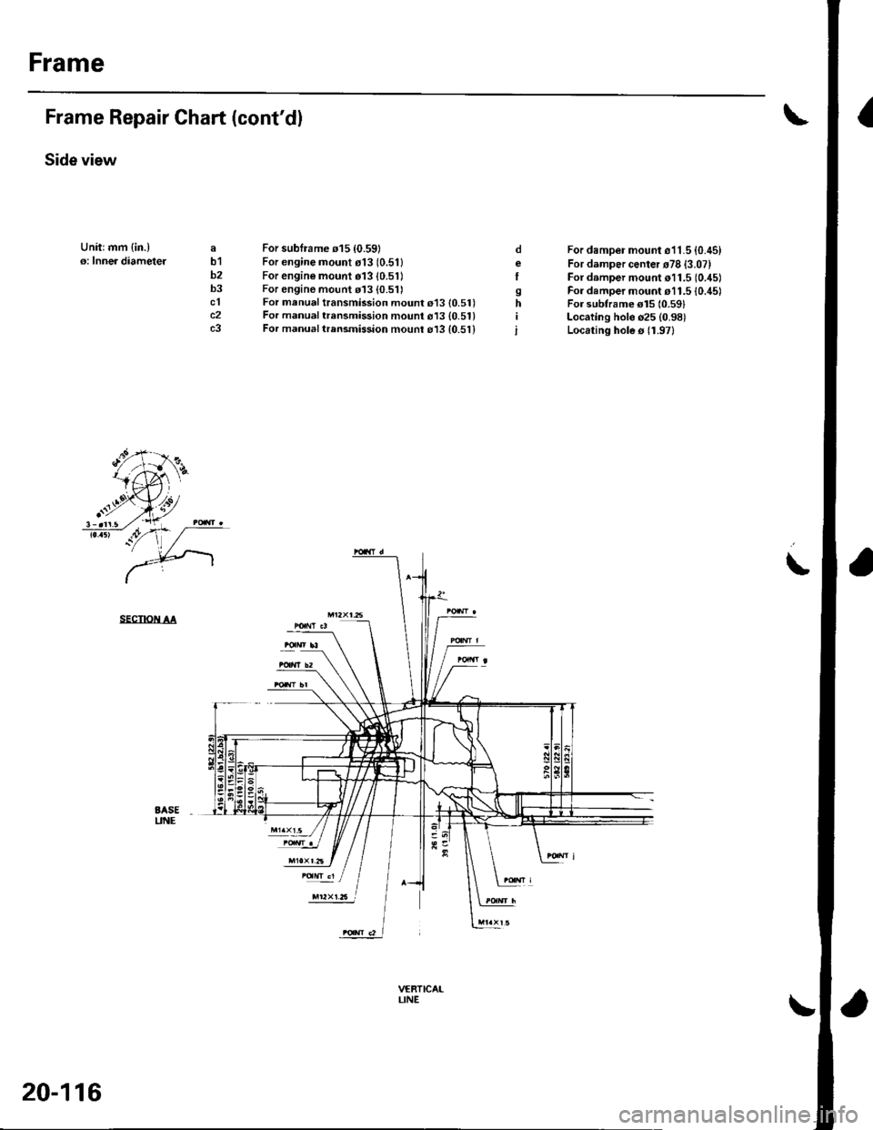
Frame
IFrame Repair Chart (cont'dl
Side view
Unitrmm {in.)o: Inner diameteJab1b2b3clc2c3
For subframe 015 {0.59}For engine mount o13 (0.511
For engine mount 01310.51)For engine mount 113 (0.511For manual transmission mount 013 {0.51)For manual trensmission mount 613 {0.51}For manual trrnsmission mounr o13 {0.51}
For damper mount o11.5 {0.45)For damper center r78 {3.07}For damper mount o11.5 (0.45)
For damper mount r11.5 {0./t5lFor subtrame el5 10.591Locating hole o25 (0.98)
Locating hole s 11.97)
oeI
sh
i
\
SECTIOiI AA
BASEUNE
trr2xt.6 l
VERTICAILINE
20-116
Page 771 of 1139
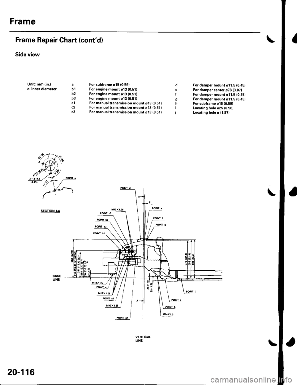
Frame
IFrame Repair Chart (cont'dl
Side view
Unitrmm {in.)o: Inner diameteJab1b2b3clc2c3
For subframe 015 {0.59}For engine mount o13 (0.511
For engine mount 01310.51)For engine mount 113 (0.511For manual transmission mount 013 {0.51)For manual trensmission mount 613 {0.51}For manual trrnsmission mounr o13 {0.51}
For damper mount o11.5 {0.45)For damper center r78 {3.07}For damper mount o11.5 (0.45)
For damper mount r11.5 {0./t5lFor subtrame el5 10.591Locating hole o25 (0.98)
Locating hole s 11.97)
oeI
sh
i
\
SECTIOiI AA
BASEUNE
trr2xt.6 l
VERTICAILINE
20-116
Page 773 of 1139
21-2
z t-'5
z t-o
z t-o
21-8
21-9
21-10
21-11
21-14
z t- to
HVAC (Heating, Ventilation, and Air Gonditioningl
Heating and Air Conditioning
SpecialTools
Comoonent Location lndex ........
A/C Service Tios and
Precautions
A,/C Refrigerant Oil
ReDlacement
General Troubleshooting
lnformation
DTC Troubleshooting Index .......
Symptom Troubleshooting
1ndex..............
System Description .....................
Circuit Diagram
DTC Troubleshooting ..................
Recirculation Control Motor
CircuitTroubleshooting .......... 21-25
Heater Control Power and Ground
Circuits Troubleshooting ........ 21-27
Condenser Fan Circuit
Troubleshooting ...................... 21-28
Radiator and Condenser Fans
Common Circuit
Troubfeshooting ...................... 21-29
Compressor Clutch Circuit
Troubleshooting ...................... 21-30
A,/C Pressure Switch Circuit
Troubleshooting ...................... 21-32
Air Mix Control Motor
Test and Reolacement ............. 21-34
Mode Control Motor
Test and Replacement ............. 21-35
Recirculation Control Motor
Test and Reolacement ............. 21-36
Evaporator Temperature Sensor
Reolacement and Test ............. 21-31
Power Transistor Test ................. 21 -38
Heater Control Panel and
Push Switch Assemblv
Removal and Installation ........ 21-38
Dust and Pollen Filter
Reolacement ..21-39
Blower Unit Removal and
lnstallation ...... 21-39
Blower Unit Comoonents
ReDlacement ............................ 21-41
Evaporator Core
Reolacement ..21-42*Heater Unit/Core
ReDlacement ..21-43
Heater Valve Cable
Adjustment .....21-46
CompressorReplacement .......... 21-47
Comoressor Clutch Check .......... 21-48
Comoressor Clutch Overhaul ..... 21-49
Compressor Thermal Protector
Reo1acement ............................ 21-51
Comoressor Relief Valve
Reolacement ............................ 21-51
Condenser Reolacement ............ 21-52
Refrigerant Recovery .................. 21-53
System Evacuation ...................... 21-54
System CharginS ......................... 21-55
Refrigerant LeakTest .................. 21-56
A,/C Svstem Tests ........................ 21-57
Page 777 of 1139
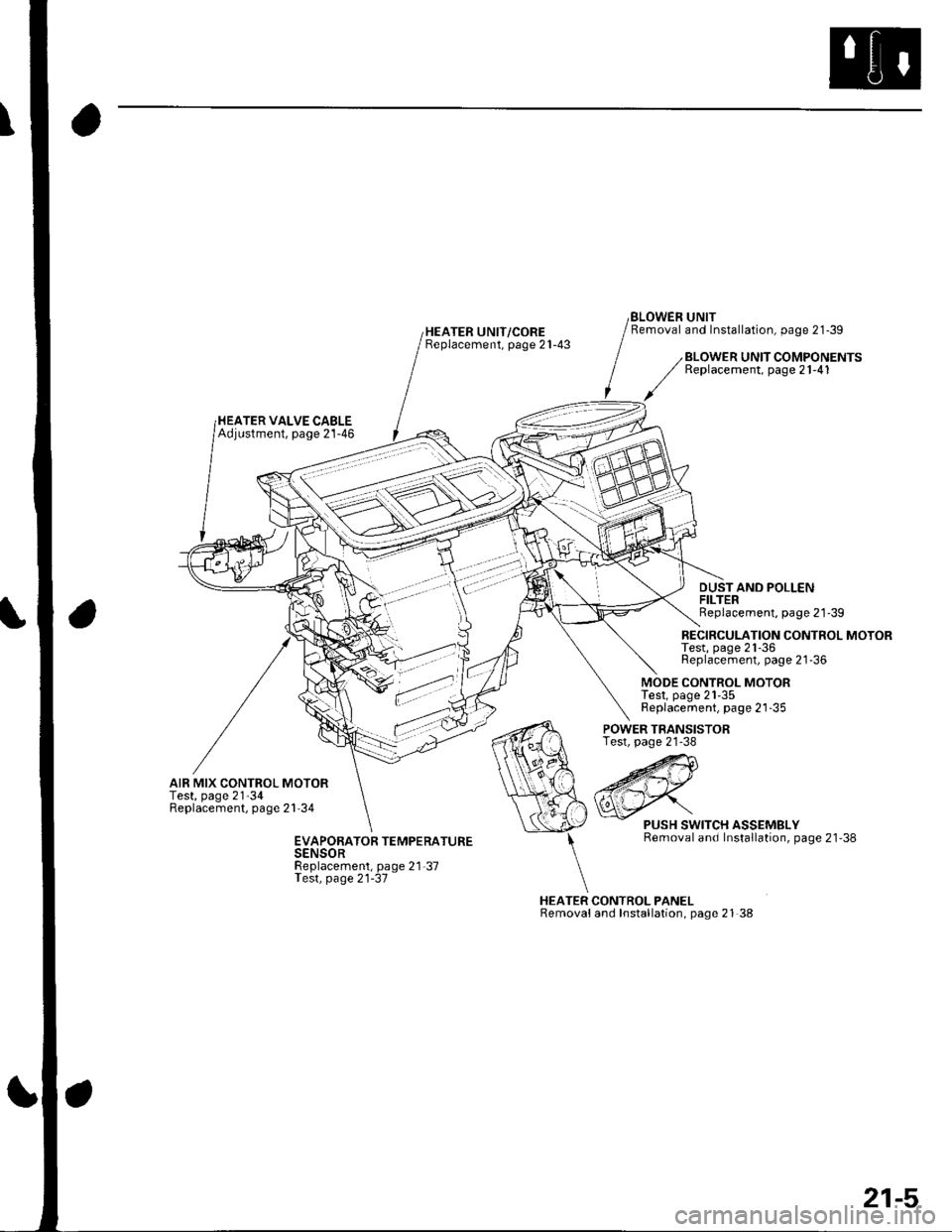
HEATER UNIT/COREBeplacement, page 21-43
BLOWEN UNITRemoval and Installation, page 21-39
HEATER VALVE CABLEAdjustment, page 21-46
BLOWER UNIT COMPONENTSReplacement, page 21-41
DUSTAND POLLENFILTERReplacement, page 21'39
RECIRCULATION CONTROL MOTORTest, page 21-36Replacement, page 21-36
MODE CONTROL MOTORTest, page 21-35Replacement, page 21-35
AIR MIX CONTROL MOTORTest, page 21'34Replacement, page 21'34
POWER TRANSISTORTest, page 21-38
HEATER CONTROL PANELRemovaland Installation, page 21 38
PUSH SWITCH ASSEMBLYRemoval and Installation, page 21'38EVAPORATOR TEMPERATURESENSORReplacement, page 21-37Test, page 21-37
21-5
Page 783 of 1139
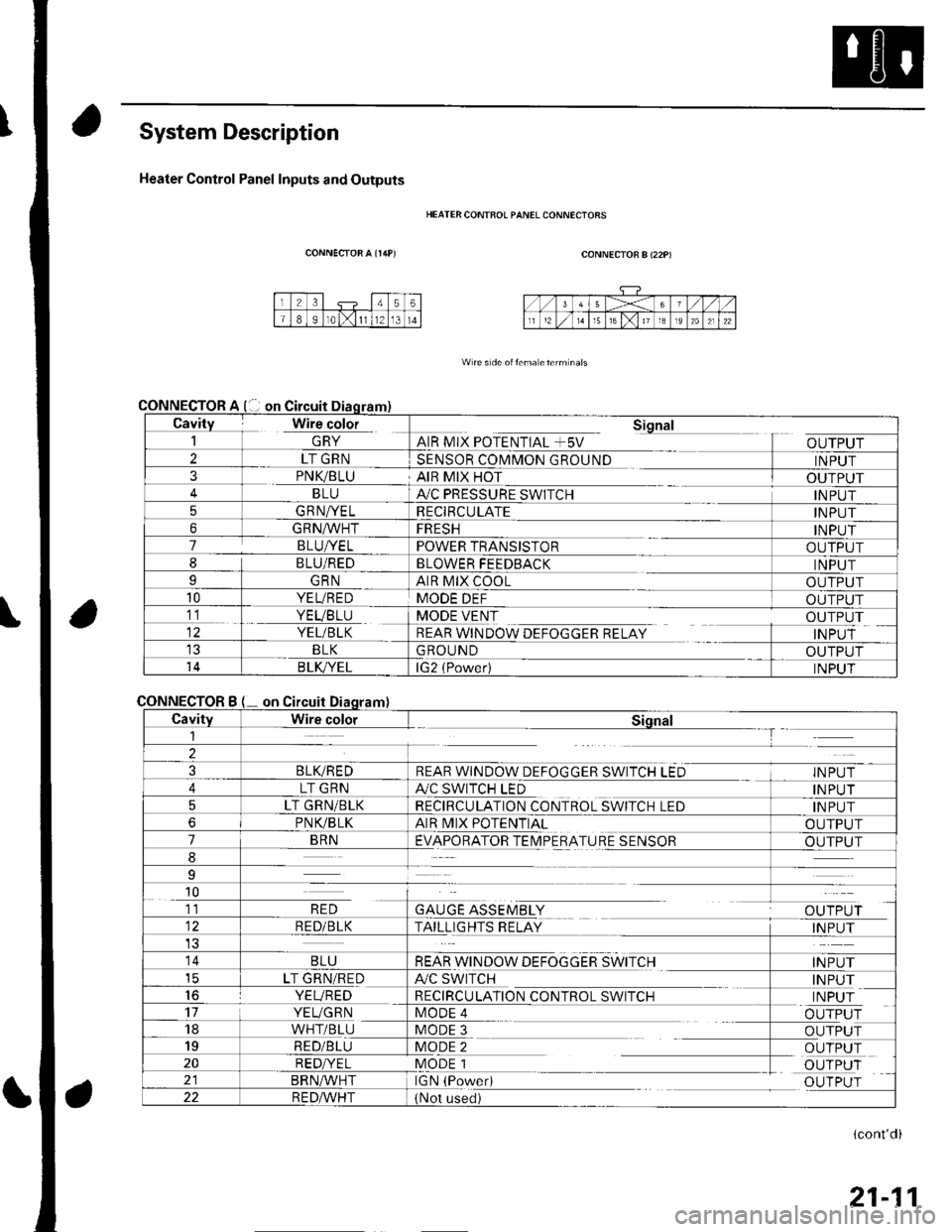
System Description
Heater Control Panel Inputs and Outputs
CONNECTOR A {r/rP)
CONNECTOR
CONNECTOR
HEATER CONTFOL PANEL CONNECIORS
CONNECTOR B (22P)
W re s de oitema eterm nals
Cavity Wire color_| \ln YAIR MIX POTENTIAL +5V
Sional
OUTPUT2LT GRNSENSOR COMMON GROUNDINPUT3PNK/BLUAIR MIX HOTOUTPUTBLUA,/C PRESSURE SWITCHINPUT5GRNA/ELRECIRCULATEINPUT6GRNA/VHTFRESHINPUT7BLUI/ELPOWER TRANSISTOROUTPUT8BLU/REDBLOWER FEEDBACKINPUTIGRNAIR MIX COOLOUTPUT10YEL/REDMODE DEFOUTPUT11. YEVBTU
YEL/BLK
MODE VENT
REAR WINDOW DEFOGGER RELAY
OUTPUT
INPUTBLKGROUNDOUTPUT14B LK/YELlG2 (Power)INPUT
Bon
CavityWire colorSiqnal1--T
2
3BLIVREDREAR WINDOW DEFOGGER SWITCH LEDINPUT
4LT GRNA./C SWITCH LEDINPUT
5LT GRN/BLKRECIRCULATION CONTROL SWITCH LEDINPUT
6PNVBLKAIR MIX POTENTIALOUTPUT
7BRNEVAPORATOR TEIMPERATURE SENSOROUTPUT
8
9
10
GAUGE ASSEMBLYal' 'TDr ri11RED
RED/BLKTAILLIGHTS RELAYINPUT
14BLUREAR WINDOW DEFOGGER SWITCHINPUTicLT GRN/REDA/C SWITCHINPUT16YEVREDRECIRCULATION CONTROL SWITCHINPUT17YEUGRNMODE 4OUTPUT18WHT/BLUMODE 3OUTPUT19RED/BLUMODE 2OUTPUT20RED/YELMODE 1OUTPUTBRN^,^/HTIGN (PowedOUTPUT22R E DA/r'HT(Not used)
(cont'd)
21-11
Page 791 of 1139
Heating and Air Gonditioning
DTC Troubleshooting {cont'd)
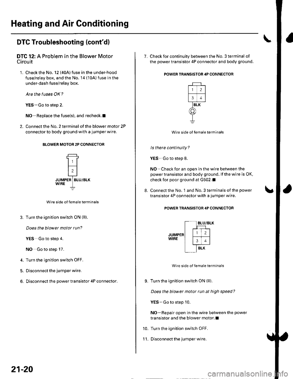
DTC 12: A Problem in the Blower Motor
Circuit
'1. Check the No. 12 (40A)fuse inthe under-hood
fuse/relay box, and the No. 14 (10A) fuse in the
under-dash f use/relay box.
Are the tuses OK?
YES-Go to step 2.
NO Replace the fuse(s), and recheck.l
2. Connect the No. 2 terminal of the blower motor 2P
connector to body ground with a jumper wire.
BLOWER MOTOB 2P CONNECTOR
JUMPER ] BLU/BLK
Wire side ol female terminals
3. Turn the ignition switch ON (ll).
Does the blowet motor run?
YES Go to step 4,
NO Go to step 17.
4. Turn the ignition switch OFF.
5. Disconnect the jumper wire.
6. Disconnect the power transistor 4P connector.
21-20
8.
7. Check for continuity between the No. 3 terminal of
the power transistor 4P connector and body ground.
POWER TRANSISTOR 4P CONNECTOR
Wire side ol temale terminals
ls there continuity?
YES-Go to step 8.
NO-Check for an open in the wire between the
power transistor and body ground. lf the wire is OK,
check for poor ground at G502.I
Connect the No. 1 and No. 3 terminals of the power
transistor 4P connector with a jumper wire.
POWER TRANSISTOR 4P CONNECTOR
Wire side of female terminals
Turn the ignition switch ON (ll).
Does the blower motor tun at high speed?
YES-Go to step 10.
NO-Repair open in the wire between the power
transistor and the blower motor.l
Turn the ignition switch OFF.
Disconnect lhe jumper wire.
9.
10.
11.
2
34
BLK
o
Page 792 of 1139
1a
13.
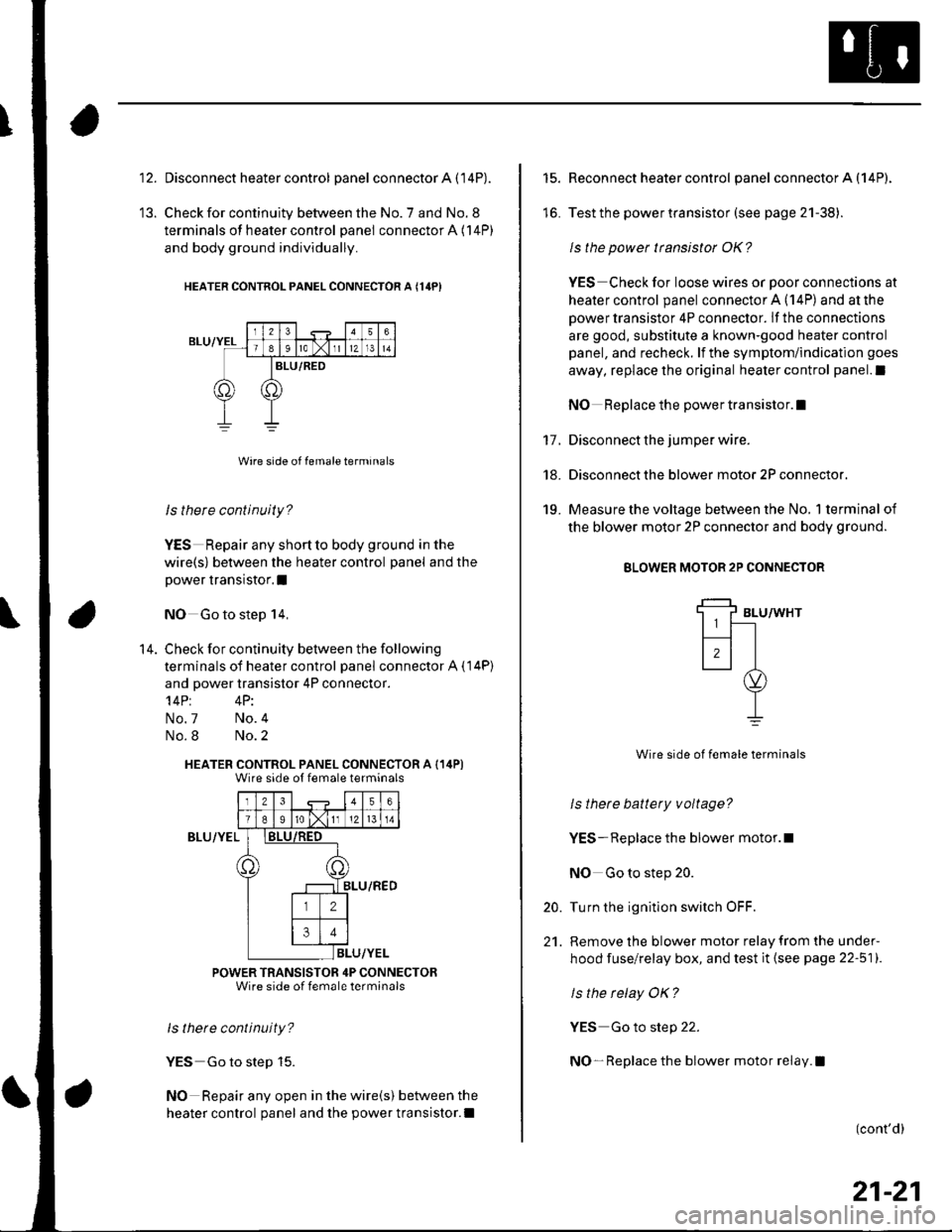
Disconnect heater control panel connector A (14P).
Check for continuity between the No. 7 and No. 8
terminals of heater control panel connector A (14P)
and body ground individually.
HEATER CONTNOL PANEL CONNECTOR A {14PI
ls there continuity?
YES Repair any shortto body ground in the
wire(s) between the heater control panel and the
power transistor.I
NO Go to step 14,
Check for continuity between the following
terminals of heater control panel connector A ( 14P)
and power transistor 4P connector.'l4Pt 4P:
No.7 No.4
No.8 No.2
HEATER CONTROL PANEL CONNECTOR A (14P)Wire side ot female terminals
Iz341516
T89ro lxlI12l 13 l 14
)8LU/RED
ILU/YEL
POWER TRANSISTOR 4P CONNECTORWire side of female terminals
ls thete continuity?
YES Go to step 15.
NO Repair any open in the wire(s) between the
heater control panel and the power transistor.l
14.
BLU/YEL
15.
lo.
17.
18.
19.
Reconnect heater control panel connector A (14P).
Test the power transistor (see page 21-38).
ls the power transistor OK?
YES Check for loose wires or poor connections at
heater control panel connector A (14P) and at the
power transistor 4P connector. lf the connections
are good, substitute a known-good heater control
panel, and recheck. lf the symptom/indication goes
away, replace the original heater control panel.l
NO Replace the power transistor.I
Disconnect the jumper wire.
Disconnect the blower motor 2P connector.
Measure the voltage between the No, 1 terminal of
the blower motor 2P connector and body ground.
BLOWER MOTOR 2P CONNECTOR
BLU/WHT
Wire side of female terminals
ls thete battery voltage?
YES- Replace the blower motor.l
NO Go to step 20.
Turn the ignition switch OFF.
Remove the blower motor relay from the under-
hood fuse/relay box, and test it (see page 22-511.
ls the relay OK?
YES Go to step 22.
NO- Replace the blower motor relay.l
20.
21.
(cont'd)
21-21
Page 809 of 1139
Heating and Air Gonditioning
a
\
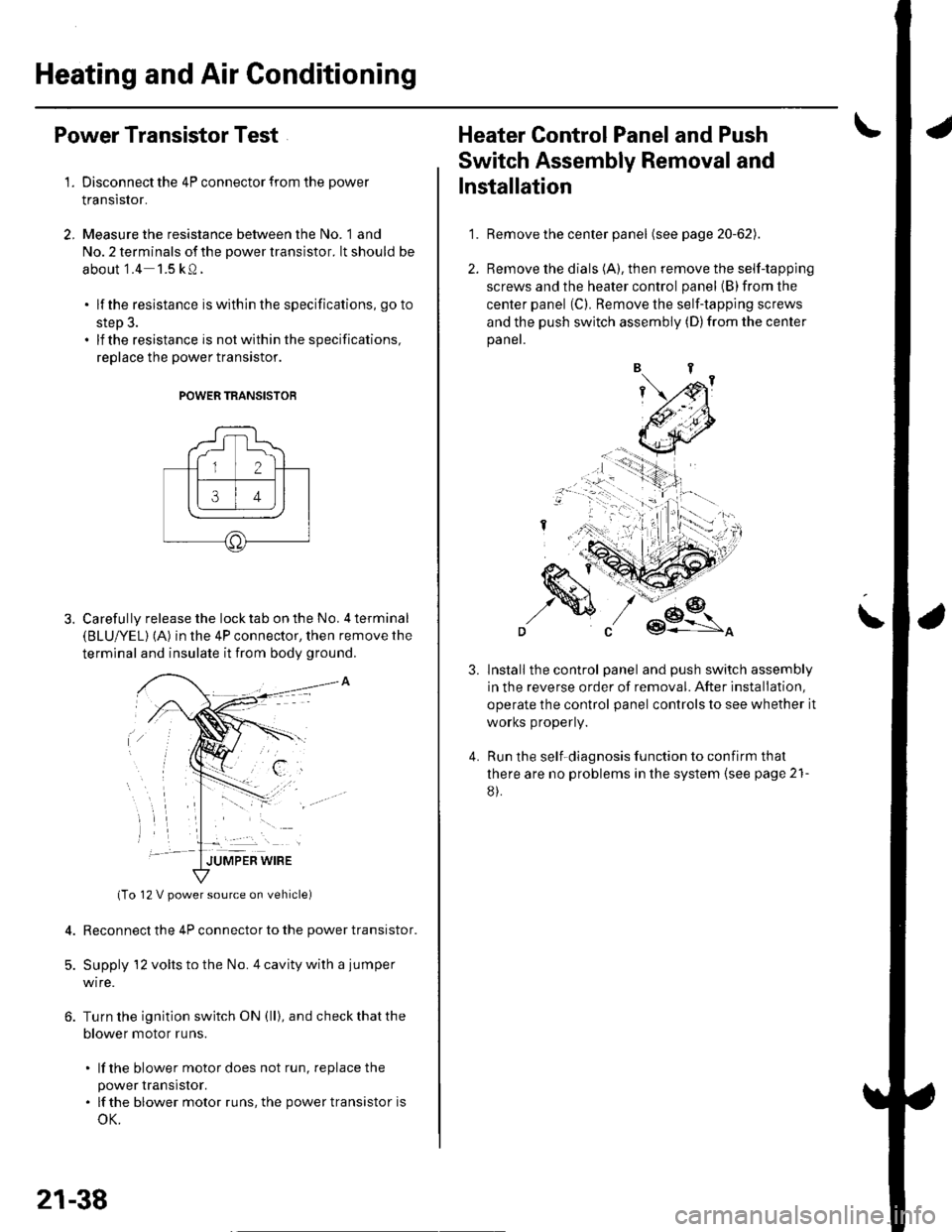
Power Transistor Test
1. Disconnect the 4P connector from the power
Iranslslor.
2, Measure the resistance between the No. 1 and
No. 2 terminals of the power transistor. lt should be
about '1.4 1.5 kQ.
. lf the resistance iswithln the specifications, go to
step 3.. lf the resistance is notwithin the specifications,
replace the power transistor.
POWER TRANSISTOB
Carefully release the lock tab on the No. 4 terminal(BLUI/EL) (A) in the 4P connector, then remove the
terminal and insulate it from body ground.
(To 12 V power source on vehicle)
Reconnect the 4P connector to the power transistor.
Supply 12 volts to the No. 4 cavity with a jumper
wire.
Turn the ignition switch ON (ll), and check that the
blower motor runs.
. lf the blower motor does not run, replace the
power rranstsror.. lf the blower motor runs,the powertransistoris
oK.
12 V power source on vehicle)
21-38
1.
Heater Control Panel and Push
Switch Assembly Removal and
Installation
Remove the center panel (see page 20-62).
Remove the dials (A), then remove the self-tapping
screws and the heater control panel (B)from the
center panel (Cl. Remove the self-tapping screws
and the push switch assembly (D)from the center
panel.
lnstall the control panel and push switch assembly
in the reverse order of removal. After installation,
operate the control panel controls to see whether it
worKs propeny.
Run the self-diagnosis function to confirm that
there are no problems in the system (see page 21-
8).
3.
4.
Page 811 of 1139
Heating and Air Gonditioning
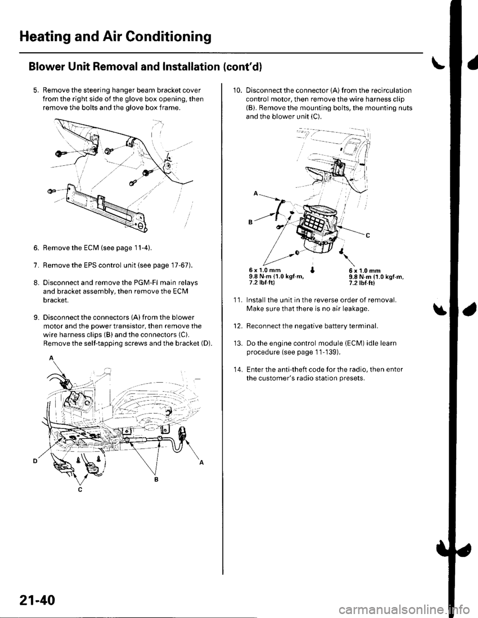
Blower Unit Removal and Installation {cont'd}
Remove the steering hanger beam bracket cover
from the right side of the glove box opening, then
remove the bolts and the olove box frame.
1.
8.
9.
Remove the ECM (see page 11-4).
Remove the EPS control unit (see page 17-67).
Disconnect and remove the PGM-Fl main relays
and bracket assembly, then remove the ECM
bracket.
Disconnect the connectors {A) from the blower
motor and the power transistor, then remove the
wire harness clips (B) and the connectors (C).
Remove the self-tapping screws and the bracket (D).
A
21-40
10. Disconnectthe connector {A) from the recirculation
control motor, then remove the wire harness clip
{B). Remove the mounting bolts, the mounting nuts
and the blower unit (C).
6x 1.0 mm I9.8 N.m (1.0 kgt.m,7.2 tbt.ftl
6x1.0mm9.8 N.m (1.0 kgf.m,?.2 tbf.ft)
11.
14.
Installlhe unit in the reverse order of removal.
Make sure that there is no air leakage.
Reconnect the negative battery terminal.
Do the engine control module (ECM) idle learn
procedure {see page 11-139).
Enter the anti-theft code for the radio, then enter
the customer's radio station presets.
\
'13.
Page 812 of 1139
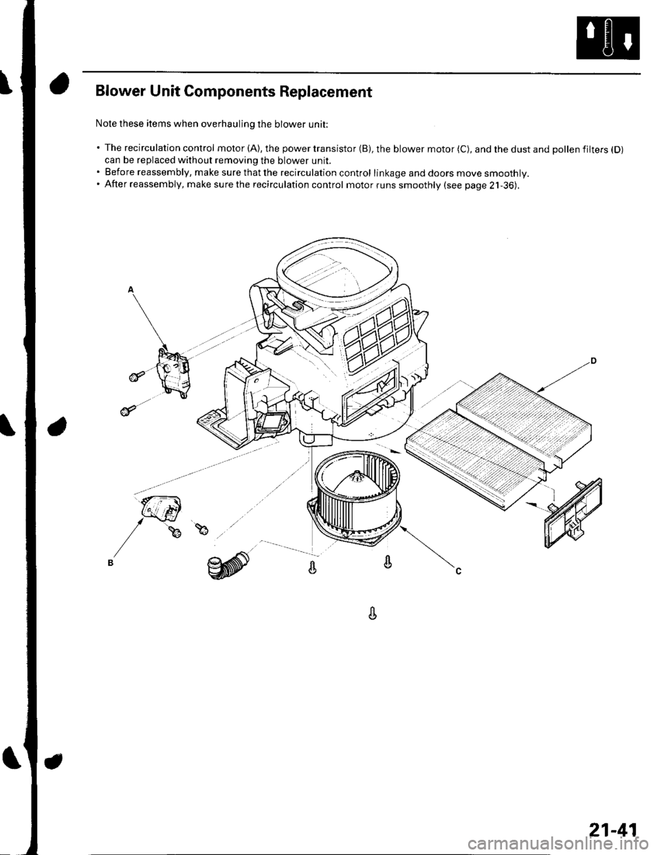
Blower Unit Components Replacement
Nole these items when overhauling the blower unit;
' The recirculation control motor (A), the power transistor (B), the blower motor (C), and the dust and pollen filtefs (D)
can be replaced without removing the blower unit.. Before reassembly, make surethatthe recirculation control linkage and doors move smoothly.. After reassembly, make surethe recirculation control motorruns smoothly (see page 2j-36).
A
21-41